US10205933B2 - Depth image acquisition apparatus and method of acquiring depth information - Google Patents
Depth image acquisition apparatus and method of acquiring depth information Download PDFInfo
- Publication number
- US10205933B2 US10205933B2 US14/622,283 US201514622283A US10205933B2 US 10205933 B2 US10205933 B2 US 10205933B2 US 201514622283 A US201514622283 A US 201514622283A US 10205933 B2 US10205933 B2 US 10205933B2
- Authority
- US
- United States
- Prior art keywords
- light
- phase
- beams
- readout
- tof
- Prior art date
- Legal status (The legal status is an assumption and is not a legal conclusion. Google has not performed a legal analysis and makes no representation as to the accuracy of the status listed.)
- Active, expires
Links
Images


Classifications
-
- H—ELECTRICITY
- H04—ELECTRIC COMMUNICATION TECHNIQUE
- H04N—PICTORIAL COMMUNICATION, e.g. TELEVISION
- H04N13/00—Stereoscopic video systems; Multi-view video systems; Details thereof
- H04N13/20—Image signal generators
- H04N13/271—Image signal generators wherein the generated image signals comprise depth maps or disparity maps
-
- H—ELECTRICITY
- H04—ELECTRIC COMMUNICATION TECHNIQUE
- H04N—PICTORIAL COMMUNICATION, e.g. TELEVISION
- H04N13/00—Stereoscopic video systems; Multi-view video systems; Details thereof
-
- G—PHYSICS
- G01—MEASURING; TESTING
- G01S—RADIO DIRECTION-FINDING; RADIO NAVIGATION; DETERMINING DISTANCE OR VELOCITY BY USE OF RADIO WAVES; LOCATING OR PRESENCE-DETECTING BY USE OF THE REFLECTION OR RERADIATION OF RADIO WAVES; ANALOGOUS ARRANGEMENTS USING OTHER WAVES
- G01S17/00—Systems using the reflection or reradiation of electromagnetic waves other than radio waves, e.g. lidar systems
- G01S17/88—Lidar systems specially adapted for specific applications
- G01S17/89—Lidar systems specially adapted for specific applications for mapping or imaging
-
- G—PHYSICS
- G01—MEASURING; TESTING
- G01S—RADIO DIRECTION-FINDING; RADIO NAVIGATION; DETERMINING DISTANCE OR VELOCITY BY USE OF RADIO WAVES; LOCATING OR PRESENCE-DETECTING BY USE OF THE REFLECTION OR RERADIATION OF RADIO WAVES; ANALOGOUS ARRANGEMENTS USING OTHER WAVES
- G01S17/00—Systems using the reflection or reradiation of electromagnetic waves other than radio waves, e.g. lidar systems
- G01S17/88—Lidar systems specially adapted for specific applications
- G01S17/89—Lidar systems specially adapted for specific applications for mapping or imaging
- G01S17/894—Three-dimensional [3D] imaging with simultaneous measurement of time-of-flight at a two-dimensional [2D] array of receiver pixels, e.g. time-of-flight cameras or flash lidar
-
- G—PHYSICS
- G01—MEASURING; TESTING
- G01S—RADIO DIRECTION-FINDING; RADIO NAVIGATION; DETERMINING DISTANCE OR VELOCITY BY USE OF RADIO WAVES; LOCATING OR PRESENCE-DETECTING BY USE OF THE REFLECTION OR RERADIATION OF RADIO WAVES; ANALOGOUS ARRANGEMENTS USING OTHER WAVES
- G01S7/00—Details of systems according to groups G01S13/00, G01S15/00, G01S17/00
- G01S7/48—Details of systems according to groups G01S13/00, G01S15/00, G01S17/00 of systems according to group G01S17/00
- G01S7/481—Constructional features, e.g. arrangements of optical elements
- G01S7/4816—Constructional features, e.g. arrangements of optical elements of receivers alone
-
- H—ELECTRICITY
- H04—ELECTRIC COMMUNICATION TECHNIQUE
- H04N—PICTORIAL COMMUNICATION, e.g. TELEVISION
- H04N13/00—Stereoscopic video systems; Multi-view video systems; Details thereof
- H04N13/20—Image signal generators
- H04N13/204—Image signal generators using stereoscopic image cameras
- H04N13/254—Image signal generators using stereoscopic image cameras in combination with electromagnetic radiation sources for illuminating objects
Definitions
- Apparatuses and methods consistent with exemplary embodiments relate to depth image acquisition acquiring depth information by using a rolling shutter method.
- 3D cameras or light detection and ranging (LIDAR) techniques for capturing distance information of an object have been researched.
- One of these research techniques is a time-of-flight (TOF) method that measures a traveling time of light, whereby a distance between an image capturing unit and a subject is measured to generate a depth image.
- TOF time-of-flight
- a predetermined wavelength for example, near-infrared (NIR) (850 nm)
- NIR near-infrared
- a TOF method may include a series of various optical processes, such as projection of light from a light source, reflection of a subject, optical modulation, capturing, and processing.
- an optical shutter method is a method in which light of a predetermined wavelength (e.g., NIR 850 nm) is projected to a subject by using an LED or LD and an optical image obtained from light of the same wavelength reflected on the subject is optically modulated by using an image intensifier or a predetermined solid state modulator.
- an image is captured by using an image sensor, such as a photodiode (PD), a charge-coupled device (CCD), or a complementary metal oxide semiconductor (CMOS) image sensor (CIS), included at a rear end of the image intensifier or the solid state modulator and an intensity value of the image is processed so as to obtain a depth image.
- a predetermined wavelength e.g., NIR 850 nm
- the CCD is a device in which metal-oxide-silicon (MOS) capacitors are very closely positioned and charge carriers are transferred to and stored in the MOS capacitors.
- the CIS is a device in which MOS transistors corresponding to the number of pixels are formed by using CMOS technology and a control circuit and a signal processing circuit are used as peripheral circuits. Furthermore, the CIS uses a switching method of detecting outputs in turn by using the MOS transistors.
- the CCD has received attention as a leading image sensor and is widely used in digital cameras, camera phones, etc. As the importance of camera phones increases, it is important to reduce the power consumption of camera phones. Thus, there is an increasing interest in the CIS. The reason is because the CIS is manufactured by using CMOS technology, which is used for manufacturing general silicon semiconductor devices, and therefore has a small size, a low price, and low power consumption.
- Examples of a method of capturing an optical image of a subject, formed in an image capturing region of an image capturing device include a global shutter method and a rolling shutter method.
- the global shutter method is a method in which all pixels in the image capturing region capture an optical image at the same time.
- the rolling shutter method is a method in which one or several pixels in the image capturing region sequentially capture an optical image.
- Both the global shutter method and the rolling shutter method may be applied to a CMOS image capturing device.
- a captured image is not transformed even if a subject moves, because all pixels capture an optical image of the subject at the same time.
- an image may be distorted due to a difference in image capturing time for each scan line because one or several pixels sequentially capture an optical image.
- a method of obtaining depth information including: sequentially projecting, to a subject, N different beams of light emitted from a light source for a time period including an idle time for each of the N different beams of light, where N is a natural number that is equal to or greater than 3; modulating, using a light modulation signal, beams of reflected light that are obtained by reflection of the N different beams of light from the subject; obtaining N phase images corresponding to the N different beams of light by capturing, using a rolling shutter method, the modulated beams of reflected light; and obtaining depth information by using the obtained N phase images.
- the idle time may include a readout time for all scan lines using the rolling shutter method.
- a method of obtaining depth information including: projecting, to a subject, light emitted from a light source; modulating, by sequentially using N light modulation signals having different phases for a time period including an idle time for each of the N light modulation signals, reflected light that is obtained by reflection of the light from the subject; obtaining N phase images corresponding to the N light modulation signals by capturing, using a rolling shutter method, the modulated reflected light; and obtaining depth information by using the N phase images.
- a method of obtaining depth information including: sequentially projecting, to a subject, N beams of light having different phases, where N is a natural number that is equal to or greater than 3; modulating, using a light modulation signal, beams of reflected light that are obtained by reflection of the N beams of light from the subject; reading out N phase images corresponding to the N beams of light by capturing the modulated beams of reflected light with each scan line using a rolling shutter method; with respect to each scan line, obtaining a first relation equation, for each of the N beams of light, among a readout phase image corresponding to an x-th beam of the N beams of light, a readout time for a previous scan line, and a phase image generated from a single beam of light; and obtaining depth information for each scan line by using the obtained N first relation equations, wherein the readout phase image comprises a portion of a phase image generated from the x-th beam of light and a portion
- the obtaining the depth information may include: obtaining a transformation matrix between the readout phase image and the phase image generated from the single beam of light, based on the N first relation equations; obtaining the phase image generated from the single beam of light by applying, to the readout phase image, an inverse matrix of the obtained transformation matrix; and obtaining a phase delay due to a time of flight (TOF) by using the phase image generated from the single beam of light.
- TOF time of flight
- the N beams of light having different phases may have a same amplitude and period, N may be 4, and the different phases may include 0 degrees, 90 degrees, 180 degrees, and 270 degrees.
- the obtaining the phase delay due to the TOF may include obtaining the phase delay according to:
- ⁇ TOF tan - 1 ⁇ ( - I CIS ( 90 ) + I CIS ( 270 ) I CIS ( 0 ) - I CIS ( 180 ) )
- ⁇ TOF denotes the phase delay due to the TOF
- I CIS (0) denotes a phase image generated from light having a phase of 0 degrees
- I CIS (90) denotes a phase image generated from light having a phase of 90 degrees
- I CIS (180) denotes a phase image generated from light having a phase of 180 degrees
- I CIS (270) denotes a phase image generated from light having a phase of 270 degrees.
- the obtaining the depth information may include: obtaining N second relation equations that relate to a difference between the readout phase image corresponding to the x-th beam of the N beams of light and a readout phase image corresponding to the (x+1)-th beam of the N beams of light; and selecting at least two of the N second relation equations and calculating the phase delay according to:
- ⁇ TOF tan - 1 ⁇ [ V i U i ] , wherein ⁇ TOF denotes the phase delay due to the TOF, V i denotes an equation that expresses sin ⁇ TOF by the readout N phase images and the readout time by using the N second relation equations, and U i denotes an equation that expresses cos ⁇ TOF by the readout N phase images and the readout time by using the N second relation equations.
- the N beams of light having different phases may have a same amplitude and period, N may be 4, and the different phases may include 0 degrees, 90 degrees, 180 degrees, and 270 degrees.
- Periods of the N beams of light may be the same as that of the light modulation signal.
- the reading out the N phase images may include accumulating the modulated beams of reflected light for a predetermined exposure time with respect to each scan line to read out the N phase images corresponding to the beams of light.
- the obtaining the depth information may include: obtaining a phase delay due to a TOF of the reflected light by using the readout N phase images, with respect to each scan line; and obtaining a distance from the subject to a depth image acquisition apparatus, which captures an image of the subject, by using the obtained phase delay.
- the method may further include generating a depth image by using the obtained depth information.
- a method of obtaining depth information including: projecting, to a subject, light emitted from a light source; modulating, by sequentially using N light modulation signals having different phases, reflected light that is obtained by reflection of the transmitted light from the subject; reading out N phase images corresponding to the N light modulation signals by capturing the modulated reflected light with each scan line using a rolling shutter method; with respect to each scan line, obtaining a first relation equation, for each of the N light modulation signals, among a readout phase image corresponding to an x-th light modulation signal of the N light modulation signals, a readout time for a previous scan line, and a phase image generated from a single light modulation signal; and obtaining depth information for each scan line by using the obtained N first relation equations, wherein the readout phase image comprises a portion of a phase image generated from the x-th light modulation signal and a portion of a phase image generated from an (x+1)-th light modul
- a depth image acquisition apparatus including: a light projector configured to sequentially project, to a subject, N different beams of light emitted from a light source for a time period including an idle time for each of the N different beams of light, where N is a natural number that is equal to or greater than 3; a light modulator configured to modulate, using a light modulation signal, beams of reflected light that are obtained by reflection of the N different beams of light from the subject; an image capturer configured to obtain N phase images corresponding to the N different beams of light by capturing, using a rolling shutter method, the modulated beams of reflected light; and a depth image processor configured to obtain depth information by using the obtained N phase images.
- a depth image acquisition apparatus including: a light projector configured to sequentially project, to a subject, N beams of light having different phases, where N is a natural number that is equal to or greater than 3; a light modulator configured to modulate, using a light modulation signal, beams of reflected light that are obtained by reflection of the N beams of light from the subject; an image capturer configured to read out N phase images corresponding to the N beams of light by capturing the modulated beams of reflected light with each scan line using a rolling shutter method; and a depth image processor configured to, with respect to each scan line, obtain a first relation equation, for each of the N beams of light, among a readout phase image corresponding to an x-th beam of the N beams of light, a readout time for a previous scan line, and a phase image generated from a single beam of light, and configured to obtain depth information for each scan line by using the obtained N first relation equations, wherein the readout phase image
- the depth image processor may be configured to: obtain a transformation matrix between the readout phase image and the phase image generated from the single beam of light, based on the N first relation equations; obtain the phase image generated from the single beam of light by applying, to the readout phase image, an inverse matrix of the obtained transformation matrix; and obtain a phase delay due to a TOF by using the phase image generated from the single beam of light.
- the depth image processor may be configured to obtain N second relation equations that relate to a difference between the readout phase image corresponding to an x-th beam of the N beams of light and a readout phase image corresponding to the (x+1)-th beam of the N beams of light, and to select at least two of the N second relation equations and calculate a phase delay according to:
- ⁇ TOF tan - 1 ⁇ [ V i U i ] , wherein ⁇ TOF denotes the phase delay due to the TOF, V i denotes an equation that expresses sin ⁇ TOF by the readout N phase images and the readout time by using the N second relation equations, and U i denotes an equation that expresses cos ⁇ TOF by the readout N phase images and the readout time by using the N second relation equations.
- FIG. 1 is a schematic structural diagram illustrating a depth image acquisition apparatus for generating a depth image by using a time-of-flight (TOF) method, according to an exemplary embodiment
- FIGS. 2A through 2D illustrate an operation of generating four different images (i.e., sub-frames) by using an image capturing device after projecting four different light transmission signals from a light source to a subject, according to an exemplary embodiment
- FIGS. 3A through 3D illustrate an operation of generating four different images (i.e., sub-frames) after modulating reflected light by using four different light modulation signals in a light modulator, according to an exemplary embodiment
- FIG. 4 illustrates a flow of an optical process according to an exemplary embodiment
- FIGS. 5A and 5B are graphs for explaining an output waveform of a light source and an output waveform of a light modulator, according to an exemplary embodiment
- FIGS. 6A and 6B are diagrams illustrating time charts for explaining operations of each component of a depth image acquisition apparatus that captures an image based on a rolling shutter method, according to an exemplary embodiment
- FIG. 8A is a diagram illustrating a time chart for explaining an operation of each component of a depth image acquisition apparatus that captures an image based on the rolling shutter method by using the method of FIG. 7A ;
- FIG. 8B is a diagram illustrating a time chart for explaining an operation of each component of a depth image acquisition apparatus that captures an image based on the rolling shutter method by using the method of FIG. 7B ;
- FIGS. 9A and 9B are flowcharts of methods of acquiring depth information, according to one or more other exemplary embodiments.
- FIGS. 10A and 10B are a diagram for explaining a relation between a phase image generated from a single beam of transmitted light and a readout phase image
- FIGS. 11A and 11B are graphs showing a value of a determinant of a transformation matrix obtained according to various exemplary embodiments
- FIG. 12 is a block diagram of a depth image acquisition apparatus according to an exemplary embodiment
- FIGS. 13A through 13D are diagrams exemplarily illustrating phase images generated by beams of transmitted light having different phases, with respect to a slanted wall.
- FIGS. 14A and 14B are diagram for showing effects obtained when capturing a depth image, with the rolling shutter method, by using any one of the methods according to one or more exemplary embodiments.
- FIG. 1 is a schematic structural diagram illustrating a depth image acquisition apparatus 100 for generating a depth image by using a time-of-flight (TOF) method, according to an exemplary embodiment.
- TOF time-of-flight
- the depth image acquisition apparatus 100 may include a light source 101 that emits light of a predetermined wavelength, a light source driving unit 102 (e.g., light driver) that drives the light source 101 , a light modulator 103 that modulates light reflected by a subject 200 (e.g., an object or a subject for image capturing), a light modulator driving unit 104 (e.g., light modulator driver) that drives the light modulator 103 , an image capturing device 105 that generates an image from the light modulated by the light modulator 103 , a depth image processor 107 that generates a depth image based on an output of the image capturing device 105 , and a control unit 106 (e.g., controller) that controls operations of the light source driving unit 102 , the light modulator driving unit 104 , the image capturing device 105 , and the depth image processor 107 .
- a control unit 106 e.g., controller
- a first lens 108 through which the reflected light is to be focused in an area of the light modulator 103 , and a filter 109 that passes through only light having a predetermined wavelength and removes background light or miscellaneous light may be further disposed on a light incident surface of the light modulator 103 .
- a second lens 110 that focuses the modulated light in an area of the image capturing device 105 may be further disposed between the light modulator 103 and the image capturing device 105 .
- the light source 101 may be, for example, a light-emitting diode (LED) or a laser diode (LD), which may emit near infrared (NIR) light having a wavelength of about 800 nm to about 1000 nm that is not visible to human eyes, for safety.
- LED light-emitting diode
- LD laser diode
- NIR near infrared
- the light source driving unit 102 may drive the light source 101 according to a control signal received from the control unit 106 , for example, in an amplitude modulation manner or a phase modulation manner.
- a light transmission signal that is projected to the subject 200 from the light source 101 may have a periodic continuous function having a predetermined period according to a driving signal of the light source driving unit 102 .
- the light transmission signal may have a waveform that is specifically defined, such as a sine wave, a ramp wave, or a square wave, but may also be a typical, undefined waveform.
- the light modulator 103 modulates light reflected by the subject 200 according to a control of the light modulator driving unit 104 .
- the light modulator driving unit 104 drives the light modulator 103 according to a control signal received from the control unit 106 .
- the light modulator 103 may modulate the amplitude of the reflected light by varying a gain of the reflected light according to a light modulation signal having a predetermined wavelength that is provided by the light modulator driving unit 104 .
- the light modulator 103 has a variable gain.
- the light modulator 103 may operate at a relatively high light modulation speed of about several tens to several hundreds MHz in order to identify a phase difference or traveling time of light according to distance.
- the light modulator 103 may be, for example, an image intensifier tube including a multi-channel plate (MCP), a gallium arsenide (GaAs)-based solid state modulator, or a thin-type modulator formed using an electro-optic material. While the light modulator 103 of a transmission type is illustrated in FIG. 1 , a reflective-type light modulator may also be used in one or more other exemplary embodiments.
- MCP multi-channel plate
- GaAs gallium arsenide
- the depth image processor 107 generates a depth image according to a depth image generating algorithm, which will be described below, based on an output of the image capturing device 105 .
- the depth image processor 107 may be, for example, an exclusive integrated circuit (IC), or may be software installed in the depth image acquisition apparatus 100 . When the depth image processor 107 is software, the depth image processor 107 may be stored in a separate portable storage medium.
- transmitted light or a light transmission signal of the light source 101 is in the form of a function having a predetermined period, such as a sine wave or a square wave, and has different phases. That is, the transmitted light or the light transmission signal may be controlled to have the same waveforms but different phases according to a control signal of the control unit 106 . While the transmitted light of the light source 101 formed to have four different phases has been described above, transmitted light of the light source 101 having the same phase and light modulation signals of the light modulator 103 having four different phases may also be formed according to another exemplary embodiment. Here, the description will focus on an exemplary embodiment in which light transmission signals having four different phases are sequentially projected in the order of 0, 180, 90, and 270 degrees.
- the light source 101 may sequentially project four different beams of transmitted light having predetermined periods and waveforms to the subject 200 according to a control of the control unit 106 and the light source driving unit 102 .
- transmitted light 1 having a phase that is 0 degrees may be generated and projected to the subject 200 during a first time period
- transmitted light 2 having a phase that is 180 degrees may be generated and projected to the subject 200 during a second time period.
- transmitted light 3 having a phase that is 90 degrees may be generated and projected to the subject 200 during a third time period
- transmitted light 4 having a phase that is 270 degrees may be generated and projected to the subject 200 during a fourth time period.
- the transmitted lights sequentially projected to the subject 200 may be in the form of a continuous function having a predetermined period, such as a sine wave.
- the subject 200 may typically have multiple surfaces having different distances from the depth image acquisition apparatus 100 , that is, different depths.
- the subject 200 illustrated in FIG. 1 has five surfaces P 1 to P 5 with different depths.
- the transmitted light is reflected by each of the five surfaces P 1 to P 5 having different depths, five reflected light beams that are differently delayed in time according to depth (that is, of different phases) are respectively generated.
- the transmitted light 1 is reflected on the five surfaces P 1 to P 5 of the subject 200 , five beams of the reflected light 1 having different phases are generated.
- the transmitted light 2 is reflected on the five surfaces P 1 to P 5 of the subject 200 , five beams of the reflected light 2 having different phases are generated.
- the transmitted light 4 is reflected by the five surfaces P 1 to P 5 to generate five beams of the reflected light 4 having different phases.
- the reflected light reflected by the surface P 1 that is the farthest from the depth image acquisition apparatus 100 is time-delayed by ⁇ P1 to arrive at the first lens 108
- the reflected light reflected on the surface P 5 that is the closest to the depth image acquisition apparatus 100 is time-delayed by ⁇ P5 , which is less than ⁇ P1 to arrive at the first lens 108 .
- the first lens 108 may focus the reflected light in an area of the light modulator 103 .
- the filter 109 that transmits or passes through only light having a predetermined wavelength may be disposed between the first lens 108 and the light modulator 103 to remove background light or miscellaneous light other than light of a used wavelength.
- the filter 109 may be an IR band pass filter that transmits or passes through the NIR wavelength band of about 850 nm. Accordingly, light incident to the light modulator 103 may mainly be light that is emitted from the light source 101 and reflected by the subject 200 .
- the filter 109 is disposed between the first lens 108 and the light modulator 103 , the positions of the first lens 108 and the filter 109 may be exchanged. For example, NIR light that has first been transmitted through the filter 109 may be focused on the light modulator 103 through the first lens 108 .
- the light modulator 103 modulates the reflected light to a light modulation signal having a predetermined wavelength.
- a period of a gain waveform in the light modulator 103 may be the same as a period of a waveform.
- the light modulator 103 may modulate the five beams of reflected light 1 that are respectively reflected by the five surfaces P 1 to P 5 of the subject 200 and provide the same to the image capturing device 105 , and may sequentially modulate the five beams of each of the reflected lights 2 through 5 and provide the same to the image capturing device 105 .
- Light having an amplitude that is modulated by using the light modulator 103 passes through the second lens 110 .
- a magnification of the light is adjusted and the light is re-focused, and then the light arrives at the image capturing device 105 .
- the modulated light is focused in an area of the image capturing device 105 through the second lens 110 .
- the image capturing device 105 generates an image by receiving the modulated light during an exposure time.
- FIGS. 2A through 2D illustrate an operation of generating four different images (i.e., sub-frames) by using an image capturing device 105 after projecting four different light transmission signals from a light source to a subject, according to an exemplary embodiment.
- the image capturing device 105 receives the five beams of the reflected light 1 , which are respectively reflected on the five surfaces P 1 to P 5 of the subject 200 and then modulated, for a predetermined exposure time period to generate an image 1 (CIS image 1 ).
- the image capturing device 105 receives the five beams of the reflected light 2 , which are respectively reflected on the five surfaces P 1 to P 5 of the subject 200 and then modulated, for a predetermined exposure time period to generate an image 2 (CIS image 2 ).
- the image capturing device 105 receives the five beams of the reflected light 4 , which are respectively reflected on the five surfaces P 1 to P 5 of the subject 200 and then modulated, for a predetermined exposure time period to generate an image 4 (CIS image 4 ).
- the images 1 through 4 may each be a sub-frame image for generating an image of a frame having depth information. For example, when assuming a period of one frame to be Td, an exposure time in the image capturing device 105 to obtain the four images 1 through 4 may be about Td/4.
- FIGS. 3A through 3D illustrate an operation of generating four different images (i.e., sub-frames) after modulating the reflected light by using four different light modulation signals in the light modulator 103 , according to an exemplary embodiment.
- the reflected light reflected by the subject 200 has the same waveform and phase in each sub-frame. There are five different phase delays ⁇ P 1 to ⁇ P 5 in the reflected light of each sub-frame according to the surfaces P 1 to P 5 of the subject 200 as described above.
- the light modulator 103 modulates the reflected light by using a light modulation signal 1 (0 degrees), and in the second sub-frame, the light modulator 103 modulates the reflected light by using a light modulation signal 2 (180 degrees) having a different phase from that of the light modulation signal 1 .
- the light modulator 103 modulates the reflected light to a light modulation signal 3 (90 degrees) having another different phase
- the light modulator 103 modulates the reflected light to another light modulation signal 4 (270 degrees).
- the light modulation signals 1 through 4 are signals having different phases of 0, 180, 90, and 270 degrees.
- the light modulation signals 1 through 4 may have the same periods and waveforms. Then, as illustrated in FIG. 3D , four different images 1 through 4 may be obtained.
- the image capturing device 105 is not limited to a CIS in one or more other exemplary embodiments.
- the four images obtained by projecting the light transmission signals having different phases (0, 180, 90, and 270 degrees) as illustrated in FIG. 2 or by using the light modulation signals 1 through 4 having different phases (0, 180, 90, and 270 degrees) as illustrated in FIG. 3 , are transmitted to the depth image processor 107 .
- the depth image processor 107 generates a depth image or depth information according to a method which will be described below, based on the four images.
- FIG. 4 illustrates a flow of an optical process according to an exemplary embodiment
- FIGS. 5A and 5B are graphs for explaining an output waveform of a light source and an output waveform of a light modulator, according to an exemplary embodiment.
- Infrared light that has transmitted or passed through an IR filter may arrive at the light modulator 103 and may be modulated to arrive at the image capturing device 105 at a rear end of the 3D image acquisition apparatus 100 .
- This series of optical processes are developed as described below.
- FIG. 5A is a waveform diagram of a light output waveform
- FIG. 5B is a driving waveform diagram of a light modulator.
- the waveform may be various periodic waves, such as a sine wave, a square wave, or a ramp wave.
- a formula for an exemplary embodiment where a light output wave (light transmission signal) is a square wave and a driving waveform of a light modulator is a sine wave will be exemplified.
- An infrared light output (or light transmission signal) is a square wave form, and emitting light optical power may be defined as expressed in Equation 4 below.
- a denotes the size of a square waveform component
- s denotes the transmission order of different beams of transmitted light
- P ave denotes DC offset, which is a DC component of output light.
- the reflected light returns after being reflected on a surface of a subject, and thus, is in the form of a square of reflectivity r in which surface reflectivity of the subject, a lens size, or the like may be comprehensively considered.
- a phase difference due to a TOF method is present and external light is also present like the infrared light.
- a modulation waveform (gain) or a light modulation signal of a light modulator (optical shutter) may be as expressed in Equation 6 below.
- G ( t ) c sin( ⁇ t )+ G ave [Equation 6]
- the light modulation signal is in the form of a combination of a sine wave (AC component) and a DC component.
- AC component a sine wave
- DC component a DC component
- c denotes the size of a sine wave component
- G ave denotes DC offset which is a DC component of output light.
- An optical signal arriving at the image capturing device is a signal obtained by multiplying the reflected light and the light modulation signal and may be as expressed in Equation 7 below.
- An output signal (or output image) emitted from the image capturing device is in the form obtained by integrating the optical signal of Equation 7 and may be as expressed in Equation 8 below.
- Equation 9 Four images sequentially captured to correspond to beams of transmitted light having different phases, based on Equation 8, may be as expressed in Equations 9 through 12 below.
- I CIS (0) rA cos ⁇ TOF +rB [Equation 9]
- I CIS (180) ⁇ rA cos ⁇ TOF +rB [Equation 10]
- I CIS (90) ⁇ rA sin ⁇ TOF +rB [Equation 11]
- I CIS (270) rA sin ⁇ TOF +rB [Equation 12]
- Equation 1 a phase delay due to a depth as in Equation 1 may be calculated.
- a depth from a subject to the depth image acquisition apparatus 100 capturing an image of the subject may be acquired as in Equation 15 by using the phase delay.
- I CIS (0) denotes a phase image that is generated from transmitted light having a phase of 0 degrees
- I CIS (90) denotes a phase image that is generated from transmitted light having a phase of 90 degrees
- I CIS (180) denotes a phase image that is generated from transmitted light having a phase of 180 degrees
- I CIS (270) denotes a phase image that is generated from transmitted light having a phase of 270 degrees.
- Equations 9 through 15 it is assumed that a depth image is generated by using a global shutter method. That is, Equations 9 through 15 do not reflect distortion that occurs due to a difference in image capturing time for each scan line of pixels when a rolling shutter method is used. Equations 9 through 15 are used for improving distortion that occurs due to a difference in image capturing time for each scan line when a depth image is captured by using the rolling shutter method.
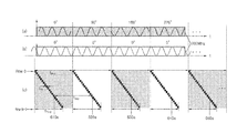
- FIGS. 6A and 6B are diagrams illustrating time charts for explaining operations of each component of a depth image acquisition apparatus that captures an image based on a rolling shutter method, according to an exemplary embodiment.
- a three-dimensional sensor using the TOF method i.e., a depth camera, sequentially obtains phase images having at least three phases by using driving signals having different phases, and thus generates a depth image.
- FIG. 6A is a diagram illustrating a time chart for explaining an operation of each component of a depth image acquisition apparatus that captures an image based on the rolling shutter method by projecting beams of transmitted light having different phases.
- FIG. 6A shows transmitted light. That is, the light source 101 may sequentially project beams of transmitted light having four different phases to a subject at regular time intervals.
- the beams of the transmitted light may have the same amplitude and the same period and phases of the beams of the transmitted light include 0 degrees, 90 degrees, 180 degrees, and 270 degrees, is exemplarily described.
- the light modulation signal has a constant amplitude and a constant period and may have the same frequency as the transmitted light.
- FIG. 6A shows an operation in which the image capturing device 105 receives modulated light for a predetermined exposure time t exp by using the rolling shutter method, generates an image, and reads out the image.
- the rolling shutter method is one of the methods of capturing a depth image by using a CIS.
- readouts are sequentially performed on scan lines of an image formed in a two-dimensional matrix form.
- the CIS sequentially reads out, from an uppermost row to a lowermost row, an image formed in the two-dimensional matrix form.
- a time for extracting an image for a scan line, e.g., a row, to store the image in an external storage device is referred to as a readout time t ro
- a next scan line is read after a lapse of time (i.e., t ro ) for reading the scan line.
- t TLro N ⁇ t ro [Equation 16]
- N denotes the number of total scan lines
- t ro denotes a time for reading one scan line
- a final depth image is an image that is obtained by capturing images at different time zones for each scan line.
- a phenomenon occurs in which a phase image generated from beams of transmitted light having different phases is included in a phase image for each scan line other than a first scan line.
- the image capturing device 105 receives a portion of a phase image generated from transmitted light having a phase of 0 degrees and a portion of a phase image generated from transmitted light having a phase of 90 degrees for a predetermined exposure time t exp and reads out a phase image corresponding to the transmitted light having a phase of 0 degrees.
- a readout time for a scan line immediately before the first scan line does not exist.
- a readout phase image corresponding to an x-th transmitted light (e.g., transmitted light having a phase of 0 degrees) is identical to a phase image generated from the x-th transmitted light.
- the exposure time t exp is delayed by a readout time t ro for a scan line immediately before the second scan line.
- a readout phase image corresponding to the x-th transmitted light includes a portion of a phase image generated from the x-th transmitted light and a portion of a phase image generated from an (x+1)-th transmitted light (e.g., transmitted light having a phase of 90 degrees).
- a generated depth image may be distorted. Aspects of one or more exemplary embodiments may solve the above problem in which, in the case of using the rolling shutter method, a generated depth image is distorted since a phase image read-out from each scan line includes phase images generated from beams of transmitted light having different phases.
- FIG. 6B is a diagram illustrating a time chart for explaining an operation of each component of a depth image acquisition apparatus that captures an image based on the rolling shutter method by using light modulation signals having different phases.
- the light source 101 may project, to a subject, beams of transmitted light having a constant amplitude, a constant period, and the same phase.
- the light modulation signal may include N light modulation signals that have a constant amplitude and period, have the same frequency as the transmitted light, and have different phases from each other.
- phases of each of the N light modulation signals are 0 degrees, 90 degrees, 180 degrees, and 270 degrees, is exemplarily described.
- FIG. 6B shows an operation in which the image capturing device 105 receives modulated light for a predetermined exposure time t exp by using the rolling shutter method, generates an image, and reads out the image.
- the image capturing device 105 receives a portion of a phase image generated by using a light modulation signal having a phase of 0 degrees and a portion of a phase image generated by using a light modulation signal having a phase of 90 degrees for a predetermined exposure time t exp and reads out a phase image corresponding to the light modulation signal having a phase of 0 degrees.
- a readout time for a scan line immediately before the first scan line does not exist.
- a readout phase image corresponding to an x-th light modulation signal (e.g., light modulation signal having a phase of 0 degrees) is identical to a phase image generated by using the x-th light modulation signal.
- the exposure time t exp is delayed by a readout time t ro for a scan line immediately before the second scan line.
- a readout phase image corresponding to the x-th light modulation signal includes a portion of a phase image generated by using the x-th light modulation signal and a portion of a phase image generated by using an (x+1)-th light modulation signal (e.g., light modulation signal having a phase of 90 degrees).
- a generated depth image may be distorted. Aspects of one or more exemplary embodiments may solve the above problem in which, in the case of using the rolling shutter method, a generated depth image is distorted since a phase image read-out from each scan line includes phase images generated from light modulation signals having different phases.
- FIGS. 7A and 7B are flowcharts of methods of acquiring depth information, according to one or more exemplary embodiments.
- FIG. 7A is a flowchart of a method of acquiring depth information by projecting beams of transmitted light having different phases, according to an exemplary embodiment.
- the problem described with reference to FIG. 6A may be solved by sequentially projecting different beams of transmitted light to a subject for a time including an idle time.
- the depth image acquisition apparatus 100 sequentially projects N different beams of transmitted light generated from a light source to a subject for a time (i.e., time period or predetermined time period) including an idle time for each of the N different beams of transmitted light (where N is a natural number that is equal to or greater than 3).
- the idle time may include a readout time for all scan lines.
- the depth image acquisition apparatus 100 modulates beams of reflected light, obtained by reflection of the N different beams of transmitted light from the subject, by using a light modulation signal.
- the depth image acquisition apparatus 100 acquires N phase images corresponding to the N different beams of transmitted light by capturing the modulated beams of reflected light using the rolling shutter method.
- the depth image acquisition apparatus 100 may accumulate the modulated beams of reflected light for a predetermined exposure time with respect to each scan line and read out the N phase images corresponding to the N different beams of transmitted light.
- the depth image acquisition apparatus 100 acquires depth information by using the N phase images.
- the depth image acquisition apparatus 100 may acquire a phase delay due to a TOF of reflected light by using N readout phase images, with respect to each scan line.
- the depth image acquisition apparatus 100 may acquire a distance from a subject to the depth image acquisition apparatus 100 , which captures an image of the subject, by using the acquired phase delay.
- the depth image acquisition apparatus 100 may generate a depth image by using the acquired depth information and display the depth image.
- a phase image read out with respect to each scan line includes only a phase image generated from a single beam of transmitted light. Accordingly, according to the depth information acquisition method of FIG. 7A , a problem, in which a phase image read out with respect to each scan line includes phase images generated from beams of transmitted light having different phases, may be mitigated or resolved.
- FIG. 7B is a flowchart of a method of acquiring (i.e., obtaining) depth information by using light modulation signals having different phases, according to an exemplary embodiment.
- the problem described with reference to FIG. 6B may be solved by sequentially using different light modulation signals for a time including an idle time.
- the depth image acquisition apparatus 100 sequentially projects, to a subject, beams of transmitted light having a constant amplitude, a constant period, and the same phase, which are generated from a light source.
- the depth image acquisition apparatus 100 modulates beams of reflected light, obtained by reflection of the beams of transmitted light from the subject, by sequentially using N different light modulation signals for a time including an idle time for each of the N different light modulation signals (where N is a natural number that is equal to or greater than 3).
- the idle time may include a readout time for all scan lines.
- the depth image acquisition apparatus 100 acquires (i.e., obtains) N phase images corresponding to the beams of transmitted light by capturing the modulated beams of reflected light using the rolling shutter method.
- the depth image acquisition apparatus 100 acquires depth information by using the N phase images.
- Operations 770 and 780 of FIG. 7B correspond to operations 730 and 740 of FIG. 7A , and thus, repeated descriptions thereof are omitted.
- a phase image read out with respect to each scan line includes only a phase image generated from a single light modulation signal. Accordingly, according to the depth information acquisition method of FIG. 7B , a problem, in which a phase image read out with respect to each scan line includes phase images generated from light modulation signals having different phases, may be mitigated or resolved.
- FIG. 8A is a diagram illustrating a time chart for explaining an operation of each component of a depth image acquisition apparatus that captures an image based on the rolling shutter method by using the method of FIG. 7A .
- FIG. 8A shows transmitted light. That is, the light source 101 may sequentially project beams of transmitted light having four different phases to a subject at regular time intervals.
- the depth image acquisition apparatus 100 may increase a projection time for each beam of transmitted light having different phases. That is, the depth image acquisition apparatus 100 may insert an idle time in the projection time, to sequentially project the beams of transmitted light. In this case, the idle time may be equal to or greater than a readout time for all scan lines.
- the light modulation signal has a constant amplitude and a constant period and may have the same frequency as the transmitted light.
- FIG. 8A shows an operation in which the image capturing device 105 receives modulated light for a predetermined exposure time t exp by using the rolling shutter method, generates an image, and reads out the image.
- the image capturing device 105 receives a phase image generated from transmitted light having a single phase of 0 degrees for a predetermined exposure time t exp and reads out a phase image corresponding to the transmitted light having a single phase of 0 degrees. That is, according to a method of an exemplary embodiment, a readout phase image includes only a phase image generated from transmitted light having a single phase by extending a projection time for each beam of transmitted light having different phases. Accordingly, a problem, in which a phase image read out with respect to each scan line includes phase images generated from beams of transmitted light having different phases, may be solved.
- a time for acquiring N phase images generated from N beams of transmitted light having different phases increases by N times an added idle time. That is, as a time for acquiring each phase image increases, a frame rate decreases. In addition, power consumption by the depth image acquisition apparatus 100 increases.
- FIG. 8B is a diagram illustrating a time chart for explaining an operation of each component of a depth image acquisition apparatus that captures an image based on the rolling shutter method by using the method of FIG. 7B .
- the light source 101 may project beams of transmitted light having a constant amplitude, a constant period, and the same phase to a subject.
- the light modulation signal may include N light modulation signals that have a constant amplitude and period, have the same frequency as the transmitted light, and have different phases from each other.
- phases of each of the N light modulation signals are 0 degrees, 90 degrees, 180 degrees, and 270 degrees, is exemplarily described.
- FIG. 8B shows an operation in which the image capturing device 105 receives modulated light for a predetermined exposure time t exp by using the rolling shutter method, generates an image, and reads out the image.
- the image capturing device 105 receives a phase image generated from transmitted light having a single phase of 0 degrees for a predetermined exposure time t exp and reads out a phase image corresponding to a light modulation signal having a phase of 0 degrees. That is, according to a method of an exemplary embodiment, a readout phase image includes only a phase image generated from a light modulation signal having a single phase by extending a light modulation time for each of light modulation signals having different phases. Accordingly, a problem, in which a phase image read out with respect to each scan line includes phase images generated from light modulation signals having different phases, may be solved.
- a time for acquiring N phase images generated from N light modulation signals having different phases increases by N times an added idle time. That is, as a time for acquiring each phase image increases, a frame rate decreases. In addition, power consumption by the depth image acquisition apparatus 100 increases.
- FIGS. 9A and 9B are flowcharts of methods of acquiring depth information, according to one or more other exemplary embodiments.
- FIG. 9A is a flowchart of a method of acquiring depth information by projecting beams of transmitted light having different phases, according to an exemplary embodiment.
- a mathematical model equation is used to solve a problem in which a generated depth image is distorted when a phase image read out with respect to each scan line includes a phase image generated from beams of transmitted light having different phases.
- the depth image acquisition apparatus 100 sequentially projects, to a subject, N beams of transmitted light having different phases, generated from a light source (where N is a natural number that is equal to or greater than 3).
- N 4 and the beams of transmitted light have the same amplitude and period and phases of 0 degrees, 90 degrees, 180 degrees, and 270 degrees.
- the depth image acquisition apparatus 100 modulates beams of reflected light, obtained by reflection of the beams of transmitted light from the subject, by using a light modulation signal.
- a period of the beams of transmitted light having different phases may be the same as that of the light modulation signal.
- the depth image acquisition apparatus 100 acquires N phase images corresponding to the beams of transmitted light by capturing the modulated beams of reflected light with respect to each scan line by using the rolling shutter method.
- the depth image acquisition apparatus 100 may accumulate the modulated beams of reflected light for a predetermined exposure time with respect to each scan line and read out the N phase images corresponding to the beams of transmitted light.
- the readout phase image includes a portion of a phase image generated from an x-th beam of transmitted light and a portion of a phase image generated from an (x+1)-th beam of transmitted light, according to a readout time for a previous scan line.
- the depth image acquisition apparatus 100 acquires, with respect to each of the N beams of transmitted light, a first relation equation among a readout phase image corresponding to an x-th beam of the N beams of transmitted light, a readout time for a previous scan line, and a phase image generated from a single beam of transmitted light, with respect to each scan line.
- the first relation equation may be, for example, as expressed in Equation 17 and is described in detail with reference to FIG. 10 below.
- I i (0) I CISi (0) +ie ( I CISi (90) ⁇ I CISi (0) )
- I i (90) I CISi (90) +ie ( I CISi (180) ⁇ I CISi (90) )
- I i (180) I CISi (180) +ie ( I CISi (270) ⁇ I CISi (180) )
- I i (270) I CISi (270) +ie ( I CISi (0)′ ⁇ I CISi (270) ) [Equation 17]
- Equation 17 depth information for each scan line is acquired by using N first relation equations shown in Equation 17.
- the depth image acquisition apparatus 100 may acquire a phase image generated from a single beam of transmitted light based on a readout phase image.
- the depth image acquisition apparatus 100 may acquire a transformation matrix between the readout phase image and the phase image generated from the single beam of transmitted light, based on the N first relation equations.
- the depth image acquisition apparatus 100 may acquire a matrix equation (i.e., determinant) as Equation 19 from Equation 17 and acquire a transformation matrix as Equation 20 from Equation 19.
- a matrix equation i.e., determinant
- the depth image acquisition apparatus 100 may acquire a phase image, which is generated from a single beam of transmitted light, by applying an inverse matrix of the acquired transformation matrix to the readout phase image.
- the depth image acquisition apparatus 100 may acquire a phase image, which is generated from a single beam of transmitted light as in Equation 21, by applying an inverse matrix of the transformation matrix of Equation 20 to the readout phase image.
- the depth image acquisition apparatus 100 may acquire a phase delay due to a TOF by using the phase image generated from the single beam of transmitted light.
- the depth image acquisition apparatus 100 may acquire a phase delay due to a TOF by applying a phase image, which is generated from a single beam of transmitted light obtained from Equation 21, to Equation 1.
- the method of acquiring depth information may not acquire a phase image, which is generated from a single beam of transmitted light, because the method may not calculate an inverse matrix when a matrix equation (i.e., determinant) of a transformation matrix is 0.
- a method of acquiring depth information may acquire a phase delay due to a TOF even though a matrix equation (i.e., determinant) of a transformation matrix is 0.
- a readout phase image has a form that is expressed by Equation 2.
- a readout phase image is as expressed in Equation 22.
- I CIS (0) r ⁇ A ⁇ cos ⁇ TOF +r ⁇ B
- I CIS (90) ⁇ r ⁇ A ⁇ sin ⁇ TOF +r ⁇ B
- I CIS (180) ⁇ r ⁇ A ⁇ cos ⁇ TOF +r ⁇ B
- I CIS (270) r ⁇ A ⁇ sin ⁇ TOF +r ⁇ B
- r denotes surface reflectivity of a subject
- A denotes a coefficient indicating the sizes of the transmitted light and light modulation signal
- B denotes a coefficient indicating direct current (DC) components of the transmitted light and light modulation signal
- ⁇ TOF denotes a phase delay due to a TOF.
- I CIS (0) denotes a phase image that is generated from transmitted light having a phase of 0 degrees
- I CIS (90) denotes a phase image that is generated from transmitted light having a phase of 90 degrees
- I CIS (180) denotes a phase image that is generated from transmitted light having a phase of 180 degrees
- I CIS (270) denotes a phase image that is generated from transmitted light having a phase of 270 degrees.
- the depth image acquisition apparatus 100 may acquire N second relation equations that relate to a difference between a readout phase image corresponding to an x-th beam of N beams of transmitted light and a readout phase image corresponding to an (x+1)-th beam of the N beams of transmitted light.
- Equation 23 a second relation equation, which relates to a difference between a readout phase image corresponding to transmitted light having a phase of 0 degrees and a readout phase image corresponding to transmitted light having a phase of 90 degrees, may be expressed as Equation 23.
- Equation 24 a second relation equation, which relates to a difference between a readout phase image corresponding to transmitted light having a phase of 90 degrees and a readout phase image corresponding to transmitted light having a phase of 180 degrees, may be expressed as Equation 24.
- I i (90) ⁇ I i (180) (1 ⁇ ie )( I CISi (90) ⁇ I CISi (180) )+ ie ( I CISi (180) ⁇ I CISi (270) ) [Equation 24]
- Equation 25 a second relation equation, which relates to a difference between a readout phase image corresponding to transmitted light having a phase of 180 degrees and a readout phase image corresponding to transmitted light having a phase of 270 degrees, may be expressed as Equation 25.
- I i (180) ⁇ I i (270) (1 ⁇ ie )( I CISi (180) ⁇ I CISi (270) )+ ie ( I CISi (270) ⁇ I CISi (0) ) [Equation 25]
- Equation 26 a second relation equation, which relates to a difference between a readout phase image corresponding to transmitted light having a phase of 270 degrees and a readout phase image corresponding to transmitted light having a phase of 0 degrees, may be expressed as Equation 26.
- I i (270) ⁇ I i (0) (1 ⁇ ie )( I CISi (270) ⁇ I CISi (0) )+ ie ( I CISi (0) ⁇ I CISi (90) ) [Equation 26]
- the depth image acquisition apparatus 100 may select at least two of the N second relation equations and then calculate a phase delay from Equation 3.
- Equations 23 through 26 may be expressed as a matrix of Equation 27.
- Equation 28 is obtained.
- the depth image acquisition apparatus 100 may select at least two rows of Equation 28 and acquire an equation V i that expresses sin ⁇ TOF by using N readout phase images and a readout time (specifically,
- the depth image acquisition apparatus 100 may select at least two rows of Equation 28 and acquire an equation U i that expresses cos ⁇ TOF by using the N readout phase images and the readout time (specifically,
- the depth image acquisition apparatus 100 may acquire a phase delay due to a TOF by applying an acquired V i and an acquired U i to Equation 3.
- Equation 29 is obtained.
- Equation 30 A process of obtaining V i and U i from Equation 29 is as expressed in Equation 30.
- Equation 31 A phase delay due to a TOF obtained from Equation 30 is as expressed in Equation 31.
- Equation 28 a calculation equation for obtaining a phase delay may be variously expressed according to at least two rows selected in Equation 28.
- a calculation equation for obtaining a phase delay may be variously derived according to a method of solving a simultaneous Equation 28 besides Equation 31.
- the depth information acquisition method described above may acquire a phase delay due to a TOF even though a matrix equation (i.e., determinant) of a transformation matrix is 0. Also, the depth information acquisition method described above may acquire a phase delay due to a TOF from a phase image read out without going through a process of acquiring a phase image that is generated from a single beam of transmitted light.
- FIG. 9B is a flowchart of a method of acquiring depth information by using light modulation signals having different phases, according to an exemplary embodiment.
- a mathematical model equation is used to solve a problem in which a generated depth image is distorted when a phase image read out with respect to each scan line includes a phase image generated from light modulation signals having different phases.
- the depth image acquisition apparatus 100 projects, to a subject, transmitted light having a constant amplitude, a constant period, and a single phase, which are generated from a light source.
- the depth image acquisition apparatus 100 modulates reflected light, obtained by reflection of the transmitted light from the subject, by using a light modulation signal.
- the light modulation signal may include N light modulation signals that have a constant amplitude and period, have the same frequency as the transmitted light, and have different phases from each other.
- N is 4 and the beams of transmitted light have the same amplitude and period and phases of 0 degrees, 90 degrees, 180 degrees, and 270 degrees.
- the depth image acquisition apparatus 100 acquires N phase images corresponding to the N light modulation signals by capturing the modulated beams of reflected light with respect to each scan line by using the rolling shutter method.
- the depth image acquisition apparatus 100 may accumulate the modulated beams of reflected light for a predetermined exposure time with respect to each scan line and read out the N phase images corresponding to the N light modulation signals.
- the readout phase images include a portion of a phase image generated from an x-th light modulation signal and a portion of a phase image generated from an (x+1)-th light modulation signal, according to a readout time for a previous scan line.
- the depth image acquisition apparatus 100 acquires, with respect to each of the N light modulation signals, a first relation equation among a readout phase image corresponding to an x-th light modulation signal of the N light modulation signals, a readout time for a previous scan line, and a phase image generated from a single light modulation signal, with respect to each scan line.
- the first relation equation is, for example, as expressed in Equation 17 and is described in detail with reference to FIG. 10 below.
- Equation 17 depth information for each scan line is acquired by using N first relation equations shown in Equation 17.
- the depth image acquisition apparatus 100 may acquire a phase image generated from a single light modulation signal based on a readout phase image.
- the depth image acquisition apparatus 100 may acquire a transformation matrix between the readout phase image and the phase image generated from the single light modulation signal, based on the N first relation equations.
- the depth image acquisition apparatus 100 may acquire a matrix equation (i.e., determinant) as Equation 19 from Equation 17 and acquire a transformation matrix as Equation 20 from Equation 19.
- a matrix equation i.e., determinant
- the depth image acquisition apparatus 100 may acquire a phase image, which is generated from a single light modulation signal, by applying an inverse matrix of the acquired transformation matrix to the readout phase image.
- the depth image acquisition apparatus 100 may acquire a phase image, which is generated from a single light modulation signal as in Equation 21, by applying an inverse matrix of the transformation matrix of Equation 20 to the readout phase image.
- the depth image acquisition apparatus 100 may acquire a phase delay due to a TOF by using the phase image generated from the single light modulation signal.
- the depth image acquisition apparatus 100 may acquire a phase delay due to a TOF by applying a phase image, which is generated from a single light modulation signal obtained from Equation 21, to Equation 1.
- the method of acquiring depth information may not acquire a phase image, which is generated from a single light modulation signal, because the method may not calculate an inverse matrix when a matrix equation (i.e., determinant) of a transformation matrix is 0.
- a method of acquiring depth information may acquire a phase delay due to a TOF even though a matrix equation (i.e., determinant) of a transformation matrix is 0.
- a readout phase image has a form that is expressed by Equation 2.
- a readout phase image may be as expressed in Equation 32.
- I CIS (0) r ⁇ A ⁇ cos ⁇ TOF +r ⁇ B
- I CIS (90) ⁇ r ⁇ A ⁇ sin ⁇ TOF +r ⁇ B
- I CIS (180) ⁇ r ⁇ A ⁇ cos ⁇ TOF +r ⁇ B
- I CIS (270) r ⁇ A ⁇ sin ⁇ TOF +r ⁇ B [Equation 32]
- r denotes surface reflectivity of a subject
- A denotes a coefficient indicating the sizes of the transmitted light and light modulation signal
- B denotes a coefficient indicating DC components of the transmitted light and light modulation signal
- ⁇ TOF denotes a phase delay due to a TOF.
- I CIS (0) denotes a phase image that is generated from a light modulation signal having a phase of 0 degrees
- I CIS (90) denotes a phase image that is generated from a light modulation signal having a phase of 90 degrees
- I CIS (180) denotes a phase image that is generated from a light modulation signal having a phase of 180 degrees
- I CIS (270) denotes a phase image that is generated from a light modulation signal having a phase of 270 degrees.
- the depth image acquisition apparatus 100 may acquire N second relation equations that relate to a difference between a readout phase image corresponding to an x-th beam of N beams of transmitted light and a readout phase image corresponding to an (x+1)-th beam of the N beams of transmitted light.
- Equation 23 a second relation equation, which relates to a difference between a readout phase image corresponding to transmitted light having a phase of 0 degrees and a readout phase image corresponding to transmitted light having a phase of 90 degrees, may be expressed as Equation 23.
- Equation 24 a second relation equation, which relates to a difference between a readout phase image corresponding to transmitted light having a phase of 90 degrees and a readout phase image corresponding to transmitted light having a phase of 180 degrees, may be expressed as Equation 24.
- Equation 25 a second relation equation, which relates to a difference between a readout phase image corresponding to transmitted light having a phase of 180 degrees and a readout phase image corresponding to transmitted light having a phase of 270 degrees, may be expressed as Equation 25.
- Equation 26 a second relation equation, which relates to a difference between a readout phase image corresponding to transmitted light having a phase of 270 degrees and a readout phase image corresponding to transmitted light having a phase of 0 degrees, may be expressed as Equation 26.
- the depth image acquisition apparatus 100 may select at least two of the N second relation equations and then calculate a phase delay from Equation 3.
- Equations 23 through 26 may be expressed as a matrix of Equation 27.
- Equation 28 is obtained.
- the depth image acquisition apparatus 100 may select at least two rows of Equation 28 and acquire an equation V i that expresses sin ⁇ TOF by using N readout phase images and a readout time (specifically, a time i ⁇ t ro for reading out previous scan lines with respect to a predetermined exposure time t exp for acquiring one phase image), that is, “ie.” Also, the depth image acquisition apparatus 100 may select at least two rows of Equation 28 and acquire an equation U i that expresses cos ⁇ TOF by using the N readout phase images and the readout time (specifically, the time i ⁇ t ro for reading out previous scan lines with respect to the predetermined exposure time t exp for acquiring one phase image), that is, “ie.”
- the depth image acquisition apparatus 100 may acquire a phase delay due to a TOF by applying an acquired V i and an acquired U i to Equation 3.
- Equation 29 is obtained.
- Equation 30 A process of obtaining V i and U i from Equation 29 is as expressed in Equation 30.
- Equation 31 A phase delay due to a TOF obtained from Equation 30 is as expressed in Equation 31.
- Equation 28 a calculation equation for obtaining a phase delay may be variously expressed according to at least two rows selected in Equation 28.
- a calculation equation for obtaining a phase delay may be variously derived according to a method of solving Equation 28 besides Equation 31.
- FIG. 10 is a diagram for explaining a relation between a phase image generated from a single beam of transmitted light and a readout phase image.
- FIG. 10 shows a phase image that is generated from a single beam of transmitted light
- (b) of FIG. 10 shows a phase image read out with respect to an (i+1)-th scan line.
- a readout phase image corresponding to an x-th beam of transmitted light includes a portion of a phase image generated from the x-th beam of transmitted light and a portion of a phase image generated from an (x+1)-th beam of transmitted light, according to a readout time for a previous scan line (a first scan line through an i-th scan line).
- the readout phase image corresponding to the x-th beam of transmitted light is obtained by reading out a phase image generated from the x-th beam of transmitted light for a time (1 ⁇ i ⁇ e) ⁇ t exp and reading out a phase image generated from the (x+1)-th beam of transmitted light for a time i ⁇ e ⁇ t exp .
- a phase image read out with respect to the (i+1)-th scan line may be represented by a relation equation between a readout time for a previous scan line and a phase image that is generated from a single beam of transmitted light, with respect to each N beam of transmitted light as in Equation 17.
- FIGS. 11A and 11B are graphs showing a value of a determinant of a transformation matrix obtained according to various exemplary embodiments.
- FIG. 11A is a graph of a determinant of a transformation matrix when using a method of obtaining a phase delay due to a TOF by using a phase image that is generated from a single beam of transmitted light obtained by using a transformation matrix.
- Equation 20 a value of a determinant is 0 when “ie” is 0.5, and thus, an inverse matrix does not exist.
- FIG. 11B is a graph of a determinant obtained by selecting at least two of N second relation equations when using a method of obtaining a phase delay due to a TOF by using the N second relation equations that relate to a difference between a readout phase image corresponding to an x-th beam of N beams of transmitted light and a readout phase image corresponding to an (x+1)-th beam of the N beams of transmitted light.
- Equation 33 a determinant obtained from Equations 29 and 30 may satisfy Equation 33.
- the depth image acquisition apparatus 100 may always calculate V i and U i and acquire a phase delay due to a TOF by applying V i and U i to Equation 3.
- FIG. 12 is a block diagram of a depth image acquisition apparatus 100 according to an exemplary embodiment.
- the depth image acquisition apparatus 100 may include a light projection unit 1210 (e.g., light projector), a light modulation unit 1220 (e.g., light modulator), an image capturing unit 1230 (e.g., image capturer), and a depth image processor 1240 .
- a light projection unit 1210 e.g., light projector
- a light modulation unit 1220 e.g., light modulator
- an image capturing unit 1230 e.g., image capturer
- a depth image processor 1240 e.g., a depth image acquisition apparatus 100 may include more or less elements than the exemplary embodiment of FIG. 12 .
- the light projection unit 1210 sequentially projects N beams of transmitted light having different phases, generated from a light source, to a subject (where N is a natural number that is equal to or greater than 3).
- the light projection unit 1210 may include a light source for generating light having a predetermined wavelength and a light source driver for driving the light source.
- the N beams of transmitted light having different phases may be discontinuously projected.
- the N beams of transmitted light having different phases may be generated from the light source.
- the light projection unit 1210 may sequentially project the N beams of transmitted light having different phases at constant time intervals.
- a phase difference between two beams of transmitted light, which are projected at subsequent time zones (e.g., time points), of the N beams of transmitted light having different phases may be a value obtained by dividing 360 degrees by N.
- N 4 and the N beams of transmitted light having different phases have the same amplitude and period and phases of 0 degrees, 90 degrees, 180 degrees, and 270 degrees.
- the light projection unit 1210 may sequentially project N different beams of transmitted light generated from the light source to a subject for a time including an idle time for each of the beams of transmitted light.
- a phase image read out with respect to each scan line includes only a phase image generated from a single beam of transmitted light. Accordingly, a problem, in which a phase image read out with respect to each scan line includes phase images generated from beams of transmitted light having different phases, may be mitigated or resolved.
- the light modulation unit 1220 modulates beams of reflected light, obtained by reflection of the N different beams of transmitted light from the subject, by using a light modulation signal.
- the light modulation unit 1220 may include a light modulator for modulating light reflected from the subject and a light modulator driver for driving the light modulator.
- the image capturing unit 1230 acquires N phase images corresponding to the N beams of transmitted light by capturing the modulated beams of reflected light by using the rolling shutter method.
- the image capturing unit 1230 may accumulate the modulated beams of reflected light for a predetermined exposure time with respect to each scan line and read out the N phase images corresponding to the beams of transmitted light.
- the readout phase images may include a portion of a phase image generated from an x-th beam of transmitted light and a portion of a phase image generated from an (x+1)-th beam of transmitted light, according to a readout time for a previous scan line.
- the depth image processor 1240 acquires depth information by using N phase images.
- the depth image processor 1240 may acquire, with respect to each of the N beams of transmitted light, a first relation equation among a readout phase image corresponding to an x-th beam of the N beams of transmitted light, a readout time for a previous scan line, and a phase image generated from a single beam of transmitted light, with respect to each scan line.
- the depth image processor 1240 may acquire depth information for each scan line by using acquired N first relation equations.
- the first relation equation may be defined by Equation 17 and Equation 18.
- the depth image processor 1240 may acquire a transformation matrix for a readout time acquired from the N first relation equations.
- the transformation matrix may be acquired as expressed in Equations 19 and 20.
- the depth image processor 1240 may acquire a phase image, which is generated from a single beam of transmitted light, by applying an inverse matrix of the acquired transformation matrix to the readout phase image.
- the depth image processor 1240 may acquire a phase image, which is generated from a single beam of transmitted light as in Equation 21, by applying an inverse matrix of the transformation matrix of Equation 20 to the readout phase image.
- the depth image processor 1240 may acquire a phase delay due to a TOF by using the phase image generated from the single beam of transmitted light.
- the depth image processor 1240 may acquire a phase delay due to a TOF by using Equation 1.
- the depth image processor 1240 may acquire a phase delay due to a TOF by using N second relation equations that relate to a difference between readout phase images corresponding to adjacent beams of transmitted light.
- the readout phase images may have a form that is expressed by Equation 2.
- the depth image processor 1240 may acquire N second relation equations that relate to a difference between a readout phase image corresponding to an x-th beam of N beams of transmitted light and a readout phase image corresponding to an (x+1)-th beam of the N beams of transmitted light.
- the N second relation equations may be expressed as Equations 23 through 26.
- the depth image processor 1240 may select at least two of the N second relation equations and then calculate a phase delay from Equation 3.
- the depth image processor 1240 may acquire Equation 28 by applying I CIS (0) , I CIS (90) , I CIS (180) , and I CIS (270) of Equation 22 to Equation 27 and acquire a phase delay due to a TOF by applying V i and U i , which are acquired by selecting at least two rows, to Equation 3.
- the depth image processor 1240 may acquire a distance from a subject to a depth image acquisition apparatus, which captures an image of the subject, by using the acquired phase delay.
- the depth image processor 1240 may acquire a distance from a subject to a depth image acquisition apparatus, which captures an image of the subject, by using Equation 15.
- the depth image processor 1240 may generate a depth image by using depth information.
- the depth image acquisition apparatus 100 may display the generated depth image.
- FIGS. 13A through 13D and 14A and 14B illustrate results of simulations performed to verify the effects of the depth image acquisition methods according to the above-described exemplary embodiments.
- FIGS. 13A through 13D and 14A and 14B illustrate results of simulations performed by using a slanted flat panel (hereinafter, referred to as a slanted wall) where a distance from a camera to the flat panel is kept constant in the vertical direction and is longer in the right side direction than in the left side direction.
- a slanted flat panel hereinafter, referred to as a slanted wall
- FIGS. 13A through 13D are diagrams exemplarily illustrating phase images generated by beams of transmitted light having different phases, with respect to a slanted wall.
- the X axis of each of FIGS. 13A through 13D indicates a true distance (in the horizontal direction of an image)
- the Y axis of each of FIGS. 13A through 13D indicates a row number in the vertical direction of an image
- the Z axis of each of FIGS. 13A through 13D indicates a phase image in a row.
- the phase image shown in FIG. 13A is not uniform but changed in the vertical direction (the Y axis).
- the phase image shown in FIG. 13B is not uniform but changed in the vertical direction (the Y axis).
- the phase image shown in FIG. 13C is not uniform but changed in the vertical direction (the Y axis).
- the phase image shown in FIG. 13D is not uniform but changed in the vertical direction (the Y axis).
- FIGS. 14A and 14B are diagram for showing effects obtained when capturing a depth image, with the rolling shutter method, by using any one of the methods according to the above-described exemplary embodiments.
- FIG. 14A shows a depth acquired from phase images acquired without using the methods according to the above-described embodiments.
- a depth is not uniform but varies depending on the row number in the vertical direction. That is, the depth shown in FIG. 14A is different from an actual depth.
- FIG. 14B shows a depth acquired from phase images acquired by using any one of the methods according to the above-described exemplary embodiments. Referring to FIG. 14B , the depth shown in FIG. 14B is equal to an actual depth.
- the depth image acquisition apparatuses described herein may include a processor, a memory for storing program data and executing the program data, a permanent storage such as a disk drive, a communications port for handling communication with external devices, and user interface devices, including a display, keys, etc.
- software modules When software modules are involved, these software modules may be stored as program instructions or computer-readable codes executable on the processor on a computer-readable media such as read-only memory (ROM), random-access memory (RAM), CD-ROMs, magnetic tapes, floppy disks, and optical data storage devices.
- ROM read-only memory
- RAM random-access memory
- CD-ROMs compact discs
- magnetic tapes magnetic tapes
- floppy disks floppy disks
- optical data storage devices optical data storage devices.
- the computer-readable recording medium can also be distributed over network-coupled computer systems so that the computer-readable code is stored and executed in a distributed fashion. This media can be read by the computer, stored in the memory, and executed by the processor.
- One or more exemplary embodiments may be described in terms of functional block components and various processing steps. Such functional blocks may be realized by any number of hardware and/or software components configured to perform the specified functions.
- the one or more exemplary embodiments may employ various integrated circuit components, e.g., memory elements, processing elements, logic elements, look-up tables, and the like, which may carry out a variety of functions under the control of one or more microprocessors or other control devices.
- the embodiments may be implemented with any programming or scripting language such as C, C++, Java, assembler, or the like, with the various algorithms being implemented with any combination of data structures, objects, processes, routines or other programming elements.
Landscapes
- Engineering & Computer Science (AREA)
- Physics & Mathematics (AREA)
- Multimedia (AREA)
- Signal Processing (AREA)
- Electromagnetism (AREA)
- Computer Networks & Wireless Communication (AREA)
- General Physics & Mathematics (AREA)
- Radar, Positioning & Navigation (AREA)
- Remote Sensing (AREA)
- Optical Radar Systems And Details Thereof (AREA)
- Length Measuring Devices By Optical Means (AREA)
- Studio Devices (AREA)
Abstract
Description
wherein ϕTOF denotes the phase delay due to the TOF, ICIS (0) denotes a phase image generated from light having a phase of 0 degrees, ICIS (90) denotes a phase image generated from light having a phase of 90 degrees, ICIS (180) denotes a phase image generated from light having a phase of 180 degrees, and ICIS (270) denotes a phase image generated from light having a phase of 270 degrees.
I CIS (θ) =r×A×cos(ϕTOF+θ)+r×B,
wherein θ denotes a phase of the light, r denotes surface reflectivity of the subject, A denotes a coefficient indicating sizes of the light and the light modulation signal, B denotes a coefficient indicating direct current (DC) components of the light and the light modulation signal, and ϕTOF denotes a phase delay due to a TOF.
wherein ϕTOF denotes the phase delay due to the TOF, Vi denotes an equation that expresses sin ϕTOF by the readout N phase images and the readout time by using the N second relation equations, and Ui denotes an equation that expresses cos ϕTOF by the readout N phase images and the readout time by using the N second relation equations.
I CIS (θ) =r×A×cos(ϕTOF+θ)+r×B,
wherein θ denotes a phase of the light, r denotes surface reflectivity of the subject, A denotes a coefficient indicating the sizes of the light and the light modulation signal, B denotes a coefficient indicating direct current (DC) components of the light and the light modulation signal, and ϕTOF denotes a phase delay due to a TOF.
wherein ϕTOF denotes the phase delay due to the TOF, Vi denotes an equation that expresses sin ϕTOF by the readout N phase images and the readout time by using the N second relation equations, and Ui denotes an equation that expresses cos ϕTOF by the readout N phase images and the readout time by using the N second relation equations.
P e (s)(t)=a·rect(ωt−θ (s))+
P r (s)(t)=r[a·rect(ωt−θ (s)−ϕTOF)+
G(t)=c sin(ωt)+
I inst. (s)(t)=P r (s)(t)×G(t)=r[a·rect(ωt−θ (s)−ϕTOF)+(
I CIS (0) =rA cos ϕTOF +rB [Equation 9]
I CIS (180) =−rA cos ϕTOF +rB [Equation 10]
I CIS (90) =−rA sin ϕTOF +rB [Equation 11]
I CIS (270) =rA sin ϕTOF +rB [Equation 12]
A′=½·ac [Equation 14]
t TLro =N×t ro [Equation 16]
I i (0) =I CISi (0) +ie(I CISi (90) −I CISi (0))
I i (90) =I CISi (90) +ie(I CISi (180) −I CISi (90))
I i (180) =I CISi (180) +ie(I CISi (270) −I CISi (180))
I i (270) =I CISi (270) +ie(I CISi (0)′ −I CISi (270)) [Equation 17]
I CIS (0) =r×A×cos ϕTOF +r×B
I CIS (90) =−r×A×sin ϕTOF +r×B
I CIS (180) =−r×A×cos ϕTOF +r×B
I CIS (270) =r×A×sin ϕTOF +r×B [Equation 22]
I i (90) −I i (180)=(1−ie)(I CISi (90) −I CISi (180))+ie(I CISi (180) −I CISi (270)) [Equation 24]
I i (180) −I i (270)=(1−ie)(I CISi (180) −I CISi (270))+ie(I CISi (270) −I CISi (0)) [Equation 25]
I i (270) −I i (0)=(1−ie)(I CISi (270) −I CISi (0))+ie(I CISi (0) −I CISi (90)) [Equation 26]
a time i×tro for reading out previous scan lines with respect to a predetermined exposure time texp for acquiring one phase image), that is, “ie.” Also, the depth
the time i×tro required for reading out previous scan lines with respect to the predetermined exposure time texp for acquiring one phase image), that is, “ie.”
I CIS (0) =r×A×cos ϕTOF +r×B
I CIS (90) =−r×A×sin ϕTOF +r×B
I CIS (180) =−r×A×cos ϕTOF +r×B
I CIS (270) =r×A×sin ϕTOF +r×B [Equation 32]
Claims (19)
I CIS (θ) =r×A×cos(ϕTOF+θ)+r×B,
I CIS (θ) =r×A×cos(ϕTOF+θ)+r×B,
Applications Claiming Priority (2)
| Application Number | Priority Date | Filing Date | Title |
|---|---|---|---|
| KR1020140114239A KR102194237B1 (en) | 2014-08-29 | 2014-08-29 | Method and apparatus for generating depth image |
| KR10-2014-0114239 | 2014-08-29 |
Publications (2)
| Publication Number | Publication Date |
|---|---|
| US20160065942A1 US20160065942A1 (en) | 2016-03-03 |
| US10205933B2 true US10205933B2 (en) | 2019-02-12 |
Family
ID=55404092
Family Applications (1)
| Application Number | Title | Priority Date | Filing Date |
|---|---|---|---|
| US14/622,283 Active 2035-12-20 US10205933B2 (en) | 2014-08-29 | 2015-02-13 | Depth image acquisition apparatus and method of acquiring depth information |
Country Status (2)
| Country | Link |
|---|---|
| US (1) | US10205933B2 (en) |
| KR (1) | KR102194237B1 (en) |
Families Citing this family (9)
| Publication number | Priority date | Publication date | Assignee | Title |
|---|---|---|---|---|
| KR102372088B1 (en) * | 2015-10-29 | 2022-03-08 | 삼성전자주식회사 | Method for generating depth image and image generating apparatus using thereof |
| KR102610830B1 (en) | 2015-12-24 | 2023-12-06 | 삼성전자주식회사 | Method and device for acquiring distance information |
| KR102752035B1 (en) | 2016-08-22 | 2025-01-09 | 삼성전자주식회사 | Method and device for acquiring distance information |
| US10557925B2 (en) | 2016-08-26 | 2020-02-11 | Samsung Electronics Co., Ltd. | Time-of-flight (TOF) image sensor using amplitude modulation for range measurement |
| KR102561099B1 (en) * | 2016-09-23 | 2023-07-28 | 삼성전자주식회사 | ToF(time of flight) capturing apparatus and method for reducing of depth distortion caused by multiple reflection thereof |
| US20210148703A1 (en) * | 2018-04-05 | 2021-05-20 | Nikon Vision Co., Ltd. | Distance detection device, optical instrument, and attitude detection method for distance detection device |
| KR102562361B1 (en) * | 2018-10-05 | 2023-08-02 | 엘지이노텍 주식회사 | Method and camera module for acquiring depth information |
| JP2023042771A (en) * | 2021-09-15 | 2023-03-28 | ソニーセミコンダクタソリューションズ株式会社 | Solid-state imaging element, method for controlling solid-state imaging element, and electronic apparatus |
| KR102613608B1 (en) * | 2021-12-14 | 2023-12-15 | 한국과학기술원 | Microarray lens cameras for high speed imaging |
Citations (33)
| Publication number | Priority date | Publication date | Assignee | Title |
|---|---|---|---|---|
| US4935616A (en) | 1989-08-14 | 1990-06-19 | The United States Of America As Represented By The Department Of Energy | Range imaging laser radar |
| US5081530A (en) | 1987-06-26 | 1992-01-14 | Antonio Medina | Three dimensional camera and range finder |
| US6057909A (en) | 1995-06-22 | 2000-05-02 | 3Dv Systems Ltd. | Optical ranging camera |
| US6088086A (en) | 1995-09-11 | 2000-07-11 | Sandia Corporation | Range determination for scannerless imaging |
| US6100517A (en) | 1995-06-22 | 2000-08-08 | 3Dv Systems Ltd. | Three dimensional camera |
| US6331911B1 (en) | 1998-02-08 | 2001-12-18 | 3Dv Systems Ltd. | Large aperture optical image shutter |
| US6794628B2 (en) | 2000-01-03 | 2004-09-21 | 3Dv Systems, Ltd. | Solid state optical shutter |
| US6856355B1 (en) | 1999-11-30 | 2005-02-15 | Eastman Kodak Company | Method and apparatus for a color scannerless range image system |
| US7095487B2 (en) | 2003-10-09 | 2006-08-22 | Honda Motor Co., Ltd. | Systems and methods for determining depth using shuttered light pulses |
| US7230685B2 (en) | 2004-01-28 | 2007-06-12 | Denso Corporation | Apparatus, method, and program for generating range-image-data |
| KR100730406B1 (en) | 2005-11-16 | 2007-06-19 | 광운대학교 산학협력단 | Stereoscopic image display device using intermediate element image |
| US20100163889A1 (en) | 2008-12-31 | 2010-07-01 | Samsung Electronics Co., Ltd. | Optical modulator with pixelization patterns |
| US20100182671A1 (en) | 2009-01-19 | 2010-07-22 | Samsung Electronics Co., Ltd. | Optical image shutter |
| KR20100084018A (en) | 2009-01-15 | 2010-07-23 | 삼성전자주식회사 | Optical image modulator and optical apparatus comprising the same and methods of manufacturing and operating optical image modulator |
| US20100308211A1 (en) | 2009-06-04 | 2010-12-09 | Samsung Electronics Co., Ltd. | Optoelectronic shutter, method of operating the same and optical apparatus including the optoelectronic shutter |
| US20100321755A1 (en) | 2009-06-17 | 2010-12-23 | Samsung Electronics Co., Ltd. | Optical modulator, methods of manufacturing and operating the same and optical apparatus including the optical modulator |
| US20100328750A1 (en) | 2009-06-24 | 2010-12-30 | Samsung Electronics Co., Ltd. | High-speed optical modulator and method of modulating light by using the same |
| US20110074659A1 (en) | 2008-12-24 | 2011-03-31 | Samsung Electronics Co., Ltd. | High speed optical shutter, method of operating the same and apparatus including the same |
| US20110170160A1 (en) | 2010-01-08 | 2011-07-14 | Samsung Electronics Co., Ltd. | Optical image shutter and method of manufacturing the same |
| KR20110085785A (en) | 2010-01-21 | 2011-07-27 | 삼성전자주식회사 | Distance information extraction method and optical device employing the method |
| US20110181936A1 (en) | 2010-01-22 | 2011-07-28 | Samsung Electronics Co., Ltd. | Optical modulator |
| US20120069176A1 (en) | 2010-09-17 | 2012-03-22 | Samsung Electronics Co., Ltd. | Apparatus and method for generating depth image |
| KR20120061379A (en) | 2010-12-03 | 2012-06-13 | 삼성전자주식회사 | Optical image modulator and method of manufacturing the same |
| US20120162380A1 (en) | 2010-12-28 | 2012-06-28 | Gwangju Institute Of Science And Technology | Optical modulator using multiple fabry-perot resonant modes and apparatus for capturing 3d image including the optical modulator |
| US20120162197A1 (en) | 2010-12-23 | 2012-06-28 | Samsung Electronics Co., Ltd. | 3-dimensional image acquisition apparatus and method of extracting depth information in the 3d image acquisition apparatus |
| KR20120077417A (en) | 2010-12-30 | 2012-07-10 | 삼성전자주식회사 | Light modulator and optical apparatus employing the same |
| US20120300038A1 (en) | 2011-05-24 | 2012-11-29 | Inha Industry Partnership Institute | Photonic crystal type light modulator and 3d image acquisition apparatus employing the same |
| US20120307084A1 (en) | 2011-06-06 | 2012-12-06 | Mantzel William E | Correcting rolling shutter using image stabilization |
| US20130101176A1 (en) | 2011-10-25 | 2013-04-25 | Samsung Electronic Co.,Ltd. | 3d image acquisition apparatus and method of calculating depth information in the 3d image acquisition apparatus |
| US8462196B2 (en) | 2007-06-11 | 2013-06-11 | Samsung Electronics Co., Ltd. | Method and apparatus for generating block-based stereoscopic image format and method and apparatus for reconstructing stereoscopic images from block-based stereoscopic image format |
| US20130201183A1 (en) | 2012-02-07 | 2013-08-08 | Samsung Electronics Co., Ltd. | 3d image acquisition apparatus and method of extracting depth information in 3d image acquisition apparatus |
| KR20140004728A (en) | 2011-03-01 | 2014-01-13 | 소니 주식회사 | Image pickup apparatus, image pickup apparatus control method, and program |
| US20140300701A1 (en) | 2013-04-08 | 2014-10-09 | Samsung Electronics Co., Ltd. | 3d image acquisition apparatus and method of generating depth image in the 3d image acquisition apparatus |
Family Cites Families (4)
| Publication number | Priority date | Publication date | Assignee | Title |
|---|---|---|---|---|
| KR20070039641A (en) * | 2005-10-10 | 2007-04-13 | 주식회사 팬택 | Method and apparatus for generating 3D image using one camera |
| KR101340797B1 (en) * | 2010-09-01 | 2013-12-11 | 주식회사 팬택 | Portable Apparatus and Method for Displaying 3D Object |
| KR101723642B1 (en) * | 2011-01-31 | 2017-04-19 | 삼성전자주식회사 | Photographing apparatus for photographing a panorama image and method thereof |
| KR20130134103A (en) * | 2012-05-30 | 2013-12-10 | 삼성전자주식회사 | Device and method for providing image in terminal |
-
2014
- 2014-08-29 KR KR1020140114239A patent/KR102194237B1/en active Active
-
2015
- 2015-02-13 US US14/622,283 patent/US10205933B2/en active Active
Patent Citations (47)
| Publication number | Priority date | Publication date | Assignee | Title |
|---|---|---|---|---|
| US5081530A (en) | 1987-06-26 | 1992-01-14 | Antonio Medina | Three dimensional camera and range finder |
| US4935616A (en) | 1989-08-14 | 1990-06-19 | The United States Of America As Represented By The Department Of Energy | Range imaging laser radar |
| US6057909A (en) | 1995-06-22 | 2000-05-02 | 3Dv Systems Ltd. | Optical ranging camera |
| US6100517A (en) | 1995-06-22 | 2000-08-08 | 3Dv Systems Ltd. | Three dimensional camera |
| US6088086A (en) | 1995-09-11 | 2000-07-11 | Sandia Corporation | Range determination for scannerless imaging |
| US6331911B1 (en) | 1998-02-08 | 2001-12-18 | 3Dv Systems Ltd. | Large aperture optical image shutter |
| US6856355B1 (en) | 1999-11-30 | 2005-02-15 | Eastman Kodak Company | Method and apparatus for a color scannerless range image system |
| US6794628B2 (en) | 2000-01-03 | 2004-09-21 | 3Dv Systems, Ltd. | Solid state optical shutter |
| US7095487B2 (en) | 2003-10-09 | 2006-08-22 | Honda Motor Co., Ltd. | Systems and methods for determining depth using shuttered light pulses |
| US7230685B2 (en) | 2004-01-28 | 2007-06-12 | Denso Corporation | Apparatus, method, and program for generating range-image-data |
| KR100730406B1 (en) | 2005-11-16 | 2007-06-19 | 광운대학교 산학협력단 | Stereoscopic image display device using intermediate element image |
| US20080211737A1 (en) | 2005-11-16 | 2008-09-04 | Eun-Soo Kim | Three-dimensional display apparatus using intermediate elemental images |
| US8462196B2 (en) | 2007-06-11 | 2013-06-11 | Samsung Electronics Co., Ltd. | Method and apparatus for generating block-based stereoscopic image format and method and apparatus for reconstructing stereoscopic images from block-based stereoscopic image format |
| KR101450670B1 (en) | 2007-06-11 | 2014-10-15 | 삼성전자 주식회사 | Block-Based Binocular Image Format Generation Method and Apparatus and Binocular Image Restoration Method and Apparatus |
| US20110074659A1 (en) | 2008-12-24 | 2011-03-31 | Samsung Electronics Co., Ltd. | High speed optical shutter, method of operating the same and apparatus including the same |
| US20100163889A1 (en) | 2008-12-31 | 2010-07-01 | Samsung Electronics Co., Ltd. | Optical modulator with pixelization patterns |
| KR20100080092A (en) | 2008-12-31 | 2010-07-08 | 삼성전자주식회사 | Optical modulator with pixelization patterns |
| KR20100084018A (en) | 2009-01-15 | 2010-07-23 | 삼성전자주식회사 | Optical image modulator and optical apparatus comprising the same and methods of manufacturing and operating optical image modulator |
| US8194303B2 (en) | 2009-01-15 | 2012-06-05 | Samsung Electronics Co., Ltd. | Optical image modulator, optical apparatus including the same, and methods of manufacturing and operating the optical image modulator |
| US20100182671A1 (en) | 2009-01-19 | 2010-07-22 | Samsung Electronics Co., Ltd. | Optical image shutter |
| US20100308211A1 (en) | 2009-06-04 | 2010-12-09 | Samsung Electronics Co., Ltd. | Optoelectronic shutter, method of operating the same and optical apparatus including the optoelectronic shutter |
| US20100321755A1 (en) | 2009-06-17 | 2010-12-23 | Samsung Electronics Co., Ltd. | Optical modulator, methods of manufacturing and operating the same and optical apparatus including the optical modulator |
| US20100328750A1 (en) | 2009-06-24 | 2010-12-30 | Samsung Electronics Co., Ltd. | High-speed optical modulator and method of modulating light by using the same |
| US20110170160A1 (en) | 2010-01-08 | 2011-07-14 | Samsung Electronics Co., Ltd. | Optical image shutter and method of manufacturing the same |
| KR20110081649A (en) | 2010-01-08 | 2011-07-14 | 삼성전자주식회사 | Optical image shutters and manufacturing method thereof |
| KR20110085785A (en) | 2010-01-21 | 2011-07-27 | 삼성전자주식회사 | Distance information extraction method and optical device employing the method |
| US8611610B2 (en) | 2010-01-21 | 2013-12-17 | Samsung Electronics Co., Ltd. | Method and apparatus for calculating a distance between an optical apparatus and an object |
| US20110181936A1 (en) | 2010-01-22 | 2011-07-28 | Samsung Electronics Co., Ltd. | Optical modulator |
| KR20120030196A (en) | 2010-09-17 | 2012-03-28 | 삼성전자주식회사 | Apparatus and method for generating depth image |
| US20120069176A1 (en) | 2010-09-17 | 2012-03-22 | Samsung Electronics Co., Ltd. | Apparatus and method for generating depth image |
| US8432599B2 (en) | 2010-12-03 | 2013-04-30 | Samsung Electronics Co., Ltd. | Optical image modulator and method of manufacturing the same |
| KR20120061379A (en) | 2010-12-03 | 2012-06-13 | 삼성전자주식회사 | Optical image modulator and method of manufacturing the same |
| US20120162197A1 (en) | 2010-12-23 | 2012-06-28 | Samsung Electronics Co., Ltd. | 3-dimensional image acquisition apparatus and method of extracting depth information in the 3d image acquisition apparatus |
| KR20120071970A (en) | 2010-12-23 | 2012-07-03 | 삼성전자주식회사 | 3d image acquisition apparatus and method of extractig depth information in the 3d image acquisition apparatus |
| KR20120075182A (en) | 2010-12-28 | 2012-07-06 | 삼성전자주식회사 | Optical modulator using multiple fabry-perot resonant modes and 3d image acquisition apparatus |
| US20120162380A1 (en) | 2010-12-28 | 2012-06-28 | Gwangju Institute Of Science And Technology | Optical modulator using multiple fabry-perot resonant modes and apparatus for capturing 3d image including the optical modulator |
| KR20120077417A (en) | 2010-12-30 | 2012-07-10 | 삼성전자주식회사 | Light modulator and optical apparatus employing the same |
| US8711463B2 (en) | 2010-12-30 | 2014-04-29 | Samsung Electronics Co., Ltd. | Light modulators and optical apparatuses including the same |
| KR20140004728A (en) | 2011-03-01 | 2014-01-13 | 소니 주식회사 | Image pickup apparatus, image pickup apparatus control method, and program |
| KR20120130937A (en) | 2011-05-24 | 2012-12-04 | 삼성전자주식회사 | Light modulator with photonic crystal and 3D image acquisition apparatus employing the same |
| US20120300038A1 (en) | 2011-05-24 | 2012-11-29 | Inha Industry Partnership Institute | Photonic crystal type light modulator and 3d image acquisition apparatus employing the same |
| US20120307084A1 (en) | 2011-06-06 | 2012-12-06 | Mantzel William E | Correcting rolling shutter using image stabilization |
| US20130101176A1 (en) | 2011-10-25 | 2013-04-25 | Samsung Electronic Co.,Ltd. | 3d image acquisition apparatus and method of calculating depth information in the 3d image acquisition apparatus |
| KR20130045018A (en) | 2011-10-25 | 2013-05-03 | 삼성전자주식회사 | 3d image acquisition apparatus and method of acqiring depth information in the 3d image acquisition apparatus |
| US20130201183A1 (en) | 2012-02-07 | 2013-08-08 | Samsung Electronics Co., Ltd. | 3d image acquisition apparatus and method of extracting depth information in 3d image acquisition apparatus |
| US20140300701A1 (en) | 2013-04-08 | 2014-10-09 | Samsung Electronics Co., Ltd. | 3d image acquisition apparatus and method of generating depth image in the 3d image acquisition apparatus |
| KR20140121710A (en) | 2013-04-08 | 2014-10-16 | 삼성전자주식회사 | An 3D image apparatus and method for generating a depth image in the 3D image apparatus |
Non-Patent Citations (1)
| Title |
|---|
| Hansard, M., Lee, S., Choi, O., and Horaud, R.(2012) Time of Flight Cameras: Principles, Methods, and Applications. Springer, pp. 95, 2012, Springer Briefs in Computer Science, ISBN 978-1-4471-4658-2. * |
Also Published As
| Publication number | Publication date |
|---|---|
| US20160065942A1 (en) | 2016-03-03 |
| KR102194237B1 (en) | 2020-12-22 |
| KR20160026189A (en) | 2016-03-09 |
Similar Documents
| Publication | Publication Date | Title |
|---|---|---|
| US20160065942A1 (en) | Depth image acquisition apparatus and method of acquiring depth information | |
| US9749613B2 (en) | 3D image acquisition apparatus and method of generating depth image in the 3D image acquisition apparatus | |
| CN103079085B (en) | Acquiring three-dimensional images device and the method calculating depth information in this device | |
| JP5739174B2 (en) | Distance information extraction method and optical apparatus employing the method | |
| US8902411B2 (en) | 3-dimensional image acquisition apparatus and method of extracting depth information in the 3D image acquisition apparatus | |
| US9310488B2 (en) | Apparatus and method for generating depth image | |
| CN106657969B (en) | Apparatus and method for obtaining images | |
| US10356380B2 (en) | Apparatus and method for acquiring depth information | |
| US9894347B2 (en) | 3D image acquisition apparatus and method of driving the same | |
| US9123164B2 (en) | 3D image acquisition apparatus and method of extracting depth information in 3D image acquisition apparatus | |
| US8369575B2 (en) | 3D image processing method and apparatus for improving accuracy of depth measurement of an object in a region of interest | |
| US10545237B2 (en) | Method and device for acquiring distance information | |
| US9989642B2 (en) | Method of acquiring depth image and image acquiring apparatus using thereof | |
| KR102194233B1 (en) | Apparatus and method for generating a depth image | |
| US10509125B2 (en) | Method and device for acquiring distance information | |
| CN121454541A (en) | Image processing apparatus and image processing method |
Legal Events
| Date | Code | Title | Description |
|---|---|---|---|
| AS | Assignment |
Owner name: SAMSUNG ELECTRONICS CO., LTD., KOREA, REPUBLIC OF Free format text: ASSIGNMENT OF ASSIGNORS INTEREST;ASSIGNOR:PARK, YONGHWA;REEL/FRAME:035024/0212 Effective date: 20150127 |
|
| STCF | Information on status: patent grant |
Free format text: PATENTED CASE |
|
| MAFP | Maintenance fee payment |
Free format text: PAYMENT OF MAINTENANCE FEE, 4TH YEAR, LARGE ENTITY (ORIGINAL EVENT CODE: M1551); ENTITY STATUS OF PATENT OWNER: LARGE ENTITY Year of fee payment: 4 |
|
| MAFP | Maintenance fee payment |
Free format text: PAYMENT OF MAINTENANCE FEE, 8TH YEAR, LARGE ENTITY (ORIGINAL EVENT CODE: M1552); ENTITY STATUS OF PATENT OWNER: LARGE ENTITY Year of fee payment: 8 |