US10202149B1 - ATV/UTV skid plate assembly - Google Patents
ATV/UTV skid plate assembly Download PDFInfo
- Publication number
- US10202149B1 US10202149B1 US15/674,858 US201715674858A US10202149B1 US 10202149 B1 US10202149 B1 US 10202149B1 US 201715674858 A US201715674858 A US 201715674858A US 10202149 B1 US10202149 B1 US 10202149B1
- Authority
- US
- United States
- Prior art keywords
- skid plate
- linear array
- closed
- apertures
- plate section
- Prior art date
- Legal status (The legal status is an assumption and is not a legal conclusion. Google has not performed a legal analysis and makes no representation as to the accuracy of the status listed.)
- Active
Links
Images


Classifications
-
- B—PERFORMING OPERATIONS; TRANSPORTING
- B62—LAND VEHICLES FOR TRAVELLING OTHERWISE THAN ON RAILS
- B62D—MOTOR VEHICLES; TRAILERS
- B62D21/00—Understructures, i.e. chassis frame on which a vehicle body may be mounted
- B62D21/02—Understructures, i.e. chassis frame on which a vehicle body may be mounted comprising longitudinally or transversely arranged frame members
-
- B—PERFORMING OPERATIONS; TRANSPORTING
- B62—LAND VEHICLES FOR TRAVELLING OTHERWISE THAN ON RAILS
- B62D—MOTOR VEHICLES; TRAILERS
- B62D25/00—Superstructure or monocoque structure sub-units; Parts or details thereof not otherwise provided for
- B62D25/20—Floors or bottom sub-units
- B62D25/2072—Floor protection, e.g. from corrosion or scratching
-
- B—PERFORMING OPERATIONS; TRANSPORTING
- B62—LAND VEHICLES FOR TRAVELLING OTHERWISE THAN ON RAILS
- B62D—MOTOR VEHICLES; TRAILERS
- B62D29/00—Superstructures, understructures, or sub-units thereof, characterised by the material thereof
- B62D29/001—Superstructures, understructures, or sub-units thereof, characterised by the material thereof characterised by combining metal and synthetic material
-
- B—PERFORMING OPERATIONS; TRANSPORTING
- B62—LAND VEHICLES FOR TRAVELLING OTHERWISE THAN ON RAILS
- B62D—MOTOR VEHICLES; TRAILERS
- B62D27/00—Connections between superstructure or understructure sub-units
- B62D27/02—Connections between superstructure or understructure sub-units rigid
Definitions
- the present invention relates generally to all-terrain vehicles (ATVs) and utility task vehicles (UTVs), and more particularly to a skid plate assembly for use on an ATV or UTV.
- ATVs all-terrain vehicles
- UTVs utility task vehicles
- ATVs and UTVs are off-road vehicles that typically travel on low-pressure tires and are designed for recreational off-road use. Smooth trails are not the norm, and many ATVs and UTVs are driven over creek beds, rutted trails, or other rough terrain where rocks, fallen trees, deep mud, etc. are frequently encountered. It is therefore common for the underside of the vehicle to scrape or otherwise come in contact with the ground or other obstacles that the driver is seeking to traverse.
- a skid plate is provided on ATVs and UTVs to protect the underside of the vehicle.
- skid plates are frequently made in multiple sections, and the edges between adjacent sections are prone to catch on rocks, logs, etc., when driving over rough terrain. This may cause one or both of the skid plate sections to bend away from the vehicle. Once a plate section has been bent, it is even more susceptible to catching on foreign objects, and is therefore increasingly likely to bend further. Once that pattern begins it is not long until the skid plate is pulled from the vehicle or is otherwise not useful for the purpose for which it is intended.
- the present invention addresses that need.
- One aspect of the present invention provides a vehicle skid plate assembly with multiple skid plate sections having closed apertures adapted to receive mounting bolts.
- the various skid plate sections are adapted to abut each other in a manner effective for the closed mounting bolt apertures of adjacent sections to overlay a single, linear array of bolt holes.
- One embodiment of the present invention includes a skid plate assembly mounted to an ATV or UTV frame.
- the frame comprises a pair of linear longitudinal frame members and a linear cross-frame member.
- Each of the three frame members includes a linear array of bolt holes.
- a skid plate assembly is mounted to the vehicle frame.
- the skid plate assembly comprises multiple skid plate sections, and each skid plate section has at least one edge portion that includes a linear array of closed apertures adapted to receive mounting bolts.
- the edges of adjacent skid plate sections abut in a manner such that the linear array of closed mounting bolt apertures of one skid plate section overlays a first set of members of one of the linear arrays of frame bolt holes, and the linear array of closed mounting bolt apertures of an adjacent skid plate section overlays a second set of members of that same linear array of frame bolt holes.
- the arrangement allows the linear array of bolt holes provided in one of the frame member to be used to mount bolts passing through the linear array of closed apertures provided in two or more skid plate sections.
- skid plate sections are mounted to three frame members such that one line of bolts connects the left skid plate section and the center skid plate section to the first linear longitudinal frame member, one line of bolts connects the right skid plate section and the center skid plate section to the second linear longitudinal frame member, and one line of bolts connects the forward skid plate section, the center skid plate section, the left skid plate section, and the right skid plate section to the linear cross-frame member.
- FIG. 1 shows a bottom plan view of an ATV/UTV skid plate assembly according to one embodiment of the present invention.
- FIG. 2 shows a top perspective view of the ATV/UTV skid plate assembly of FIG. 1 .
- FIG. 3 shows a bottom plan view of the front ATV/UTV skid plate section of the ATV/UTV skid plate assembly of FIG. 1 .
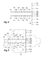
- FIG. 4 shows a bottom plan view of the center ATV/UTV skid plate section of the ATV/UTV skid plate assembly of FIG. 1 .
- FIG. 5 shows a bottom plan view of the left ATV/UTV skid plate section of the ATV/UTV skid plate assembly of FIG. 1 .
- FIG. 6 shows a bottom plan view of the right ATV/UTV skid plate section of the ATV/UTV skid plate assembly of FIG. 1 .
- FIG. 7 shows a bottom plan view of the ATV/UTV skid plate assembly of FIG. 1 , showing the linear arrays of bolts used to connect the skid plate to the vehicle.
- FIG. 8 shows a top perspective view of the frame member of the ATV/UTV skid plate assembly of FIG. 1 .
- FIG. 9 shows a bottom plan view of the ATV/UTV skid plate assembly of FIG. 1 , with the skid plate sections being shown in phantom, showing the linear arrays of bolts used to connect the skid plate to the vehicle.
- one aspect of the present invention provides a utility task vehicle assembly comprising a vehicle frame and a skid plate assembly.
- the vehicle frame has a forward end and a rearward end, and comprises a first linear longitudinal frame member, a second linear longitudinal frame member, and a linear cross-frame member.
- the first linear longitudinal frame member includes a first linear array of bolt holes
- the second linear longitudinal frame member includes a second linear array of bolt holes.
- the linear cross-frame member includes a third linear array of bolt holes.
- a skid plate assembly is mounted to the vehicle frame.
- the skid plate assembly comprises a forward skid plate section, a center skid plate section, a left skid plate section, and a right skid plate section.
- the forward skid plate section has a bottom edge portion bounded by a bottom edge, and includes a linear array of closed apertures adapted to receive mounting bolts.
- the linear array preferably includes two or more apertures.
- the center skid plate section has a forward edge portion bounded by a forward edge, and includes one or more closed apertures adapted to receive mounting bolts. To the extent more than one aperture is included, the apertures are arranged in a line to provide a linear array of apertures.
- the center skid plate section also has a left-hand edge portion bounded by a left-hand edge, and includes a linear array of closed apertures adapted to receive mounting bolts.
- the linear array preferably includes two or more apertures.
- the center skid plate section also has a right-hand edge portion bounded by a right-hand edge, and includes a linear array of closed apertures adapted to receive mounting bolts.
- the linear array preferably includes two or more apertures.
- the left skid plate section has a forward edge portion bounded by a forward edge, and includes one or more closed apertures adapted to receive mounting bolts. To the extent more than one aperture is included, the apertures are arranged in a line to provide a linear array of apertures.
- the left skid plate section also has a right-hand edge portion bounded by a right-hand edge, and includes a linear array of closed apertures adapted to receive mounting bolts.
- the linear array preferably includes two or more apertures.
- the right skid plate section has a forward edge portion bounded by a forward edge, and includes one or more closed apertures adapted to receive mounting bolts. To the extent more than one aperture is included, the apertures are arranged in a line to provide a linear array of apertures.
- the right skid plate section also has a left-hand edge portion bounded by a left-hand edge, and includes a linear array of closed apertures adapted to receive mounting bolts.
- the linear array preferably includes two or more apertures.
- the bottom edge of the forward skid plate section abuts the forward edge of the center skid plate section and the forward edge of the left skid plate section and the forward edge of the right skid plate section.
- the plates abut in a manner such that the linear array of closed mounting bolt apertures of the bottom edge portion of the forward skid plate overlays a first set of members of the third linear array of bolt holes, and in a manner such that the linear array of closed mounting bolt apertures of the forward edge portion of the center skid plate overlays a second set of members of said third linear array bolt holes, and in a manner such that the linear array of closed mounting bolt apertures of the forward edge portion of the left skid plate overlays a third set of members of said third linear array of bolt holes, and in a manner such that the linear array of closed mounting bolt apertures of the forward edge portion of the right skid plate overlays a fourth set of members of said third linear array of bolt holes.
- the first, second, third and fourth sets of members of the third linear array of bolt holes are mutually exclusive sets
- the center skid plate section abuts against the left- and right-hand skid plate sections in a manner such that the linear array of closed mounting bolt apertures of the left-hand edge portion of the center skid plate overlays a first set of members of the first linear array of bolt holes, and in a manner such that the linear array of closed mounting bolt apertures of the right-hand edge portion of the center skid plate overlays a first set of members of said second linear array bolt holes, and in a manner such that the linear array of closed mounting bolt apertures of the right-hand edge portion of the left skid plate overlays a second set of members of the first linear array of bolt holes, and in a manner such that the linear array of
- the arrangement described above allows the linear array of bolt holes provided in the third longitudinal frame member to be used to mount bolts passing through the linear array of closed apertures provided in the bottom portion of the forward skid plate section, and to mount bolts passing through the linear array of closed apertures provided in the forward edge portion of the left skid plate section, and to mount bolts passing through the linear array of closed apertures provided in the forward edge portion of the right skid plate section.
- the four plates abut so that three lines of bolts are used—one line of bolts connecting the left skid plate section and the center skid plate section to the first linear longitudinal frame member, one line of bolts connecting the right skid plate section and the center skid plate section to the second linear longitudinal frame member, and one line of bolts connecting the forward skid plate section, the center skid plate section, the left skid plate section, and the right skid plate section to the linear cross-frame member.
- Another embodiment of the present invention provides a vehicle skid plate assembly, comprising a multiplicity of skid plate sections.
- the assembly includes:
- the bottom edge of the forward skid plate section is adapted to abut the forward edge of the center skid plate section, the forward edge of the left skid plate section, and the forward edge of the right skid plate section in a manner effective to cause the closed mounting bolt apertures of the bottom edge portion of the forward skid plate and the closed mounting bolt apertures of the forward edge portion of the center skid plate and the closed mounting bolt apertures of the forward edge portion of the left skid plate and the closed mounting bolt apertures of the forward edge portion of the right skid plate to overlay a first linear array of bolt holes.
- the left-hand edge of the center skid plate section is adapted to abut the right-hand edge of the left skid plate section in a manner effective to cause the closed mounting bolt apertures of the left-hand edge portion of the center skid plate and the closed mounting bolt apertures of the right-hand edge portion of the left skid plate to overlay a second linear array of bolt holes.
- the right-hand edge of the center skid plate section is adapted to abut the left-hand edge of the right skid plate section in a manner effective to cause the closed mounting bolt apertures of the right-hand edge portion of the center skid plate and the closed mounting bolt apertures of the left-hand edge portion of the right skid plate to overlay a third linear array of bolt holes.
- a utility task vehicle assembly comprising:
- the bottom edge of the forward skid plate section abuts the forward edge of the center skid plate section, the forward edge of the left skid plate section, and the forward edge of the right skid plate section so that the linear array of closed mounting bolt apertures of the bottom edge portion of the forward skid plate overlays a first set of members of the third linear array of bolt holes, at least one or the closed mounting bolt apertures of the forward edge portion of the center skid plate overlays a second set of members of said third linear array bolt holes, the linear array of closed mounting bolt apertures of the forward edge portion of the left skid plate overlays a third set of members of said third linear array of bolt holes, and the linear array of closed mounting bolt apertures of the forward edge portion of the right skid plate overlays a fourth set of members of said third linear array of bolt holes, and
- a utility task vehicle assembly comprising two or more skid plate sections and one or more frame members; wherein at least one frame member includes a first linear array of bolt holes adapted to receive mounting bolts, and wherein one of said two or more skid plate sections includes a first linear array of two or more closed apertures adapted to receive mounting bolts, and another of said two or more skid plate sections includes a second linear array of two or more closed apertures adapted to receive mounting bolts.
- Said first of said two or more skid plate sections abuts said second of said two or more skid plate sections so that the linear array of two or more closed mounting bolt apertures of the first skid plate section overlays a first set of members of the first linear array of bolt holes, and the linear array of two or more closed mounting bolt apertures of the second skid plate section overlays a second set of members of the first linear array of bolt holes.
- a utility task vehicle assembly comprising three or more skid plate sections and two or more frame members.
- a first of said two or more frame members includes a first linear array of bolt holes adapted to receive mounting bolts, and a second of said two or more frame member includes a second linear array of bolt holes adapted to receive mounting bolts.
- a first of the three or more skid plate sections includes a first linear array of two or more closed apertures adapted to receive mounting bolts.
- a second of the three or more skid plate sections includes a first linear array of two or more closed apertures adapted to receive mounting bolts, and a second linear array of two or more closed apertures adapted to receive mounting bolts, with the first linear array preferably being perpendicular to the second linear array.
- the first of said three or more skid plate sections abuts the third of said three or more skid plate sections so that the first linear array of two or more closed mounting bolt apertures of the third skid plate section overlays a third set of members of the first linear array of bolt holes.
- the second of the three or more skid plate sections abuts the third of the three or more skid plate sections so that the second linear array of two or more closed mounting bolt apertures of the second skid plate section overlays a first set of members of the second linear array of bolt holes, and the second linear array of two or more closed mounting bolt apertures of the third skid plate section overlays a second set of members of the second linear array of bolt holes.
- FIG. 1 shows one embodiment of the utility task vehicle assembly of the present invention.
- Assembly 1 includes forward skid plate section 10 , center skid plate section 20 , left skid plate section 30 , and right skid plate section 40 .
- First linear longitudinal frame member 51 and second linear longitudinal frame member 52 are also shown.
- FIG. 2 shows another view of the utility task vehicle assembly of FIG. 1 .
- Assembly 1 includes forward skid plate section 10 , center skid plate section 20 , left skid plate section 30 , and right skid plate section 40 .
- First linear longitudinal frame member 51 and second linear longitudinal frame member 52 are also shown, as is linear cross-frame member 53 .
- FIG. 3 shows a bottom plan view of forward skid plate section 10 .
- Forward skid plate section 10 has a bottom edge portion 11 bounded by a bottom edge 11 a , wherein the bottom edge portion of said forward skid plate section includes a linear array 14 a - 14 e of closed apertures adapted to receive mounting bolts.
- Bottom edge 11 a extends all of the way along the side of the section, with the reference number provided in the figure identifying only some representative portions of the edge.
- a closed aperture is an aperture that is surrounded by solid material all of the way around the aperture.
- the closed apertures of the present invention are not open to one side, as apertures used in some prior art skid plate assemblies may be.
- the use of closed apertures provides a more secure mounting that is less prone to being pulled from the frame when a skid plate edge contacts the ground.
- FIG. 4 shows a bottom plan view of center skid plate section 20 .
- Center skid plate section 20 has a forward edge portion 21 bounded by a forward edge 21 a .
- Forward edge portion 21 includes a linear array 25 a and 25 b of closed apertures adapted to receive mounting bolts.
- Center skid plate section 20 also has a left-hand edge portion 22 bounded by a left-hand edge 22 a .
- Left-hand edge portion 22 of center skid plate section 20 includes a linear array 26 a - 26 e of closed apertures adapted to receive mounting bolts.
- Center skid plate section 20 also has a right-hand edge portion 23 bounded by a right-hand edge 23 a .
- center skid plate section 20 includes closed apertures that are surrounded by solid material all of the way around the aperture.
- the closed apertures are not open to one side, and provide a more secure mounting that is less prone to being pulled from the frame when a skid plate edge contacts the ground.
- FIG. 5 shows a bottom plan view of left skid plate section 30 .
- Left skid plate section 30 has a forward edge portion 31 bounded by a forward edge 31 a .
- Forward edge portion 31 includes a linear array 35 a and 35 b of closed apertures adapted to receive mounting bolts.
- Left skid plate section 30 also has a right-hand edge portion 32 bounded by a right-hand edge 32 a .
- Right-hand edge portion 32 of left skid plate section 30 includes a linear array 36 a - 36 e of closed apertures adapted to receive mounting bolts.
- forward edge 31 a and right-hand edge 33 a each extend all of the way along the side of the section, with the reference numbers provided in the figure identifying only some representative portions of the edges.
- left skid plate section 30 includes closed apertures that are surrounded by solid material all of the way around the aperture.
- the closed apertures are not open to one side, and provide a more secure mounting that is less prone to being pulled from the frame when a skid plate edge contacts the ground.
- FIG. 6 shows a bottom plan view of right skid plate section 40 .
- Right skid plate section 40 has a forward edge portion 41 bounded by a forward edge 41 a .
- Forward edge portion 41 includes a linear array 45 a and 45 b of closed apertures adapted to receive mounting bolts.
- Right skid plate section 40 also has a left-hand edge portion 42 bounded by a left-hand edge 42 a .
- Left-hand edge portion 42 of right skid plate section 40 includes a linear array 46 a - 46 e of closed apertures adapted to receive mounting bolts.
- forward edge 41 a and left-hand edge 42 a each extend all of the way along the side of the section, with the reference numbers provided in the figure identifying only some representative portions of the edges.
- right skid plate section 40 includes closed apertures that are surrounded by solid material all of the way around the aperture.
- the closed apertures are not open to one side, and provide a more secure mounting that is less prone to being pulled from the frame when a skid plate edge contacts the ground.
- the bottom edge 11 a of forward skid plate section 10 abuts the forward edge 21 a of center skid plate section 20 in a manner such that the linear array of closed mounting bolt apertures of the bottom edge portion of the forward skid plate overlays a first set of members of the third linear array of bolt holes, and the linear array of closed mounting bolt apertures of the bottom edge portion of the forward skid plate overlays a first set of members of the third linear array of bolt holes.
- the linear array of closed mounting bolt apertures of the forward edge portion of the center skid plate overlays a second set of members of said third linear array bolt holes
- the linear array of closed mounting bolt apertures of the forward edge portion of the left skid plate overlays a third set of members of said third linear array of bolt holes
- the linear array of closed mounting bolt apertures of the forward edge portion of the right skid plate overlays a fourth set of members of said third linear array of bolt holes.
- the left-hand edge of the center skid plate section abuts the right-hand edge of the left skid plate section so that the linear array of closed mounting bolt apertures of the left-hand edge portion of the center skid plate overlays a first set of members of said first linear array of bolt holes, and the linear array of closed mounting bolt apertures of the right-hand edge portion of the left skid plate overlays a second set of members of the first linear array of bolt holes.
- This provides a linear array A 2 of connections where bolts pass though the closed mounting bolt apertures and are connected to the frame in a manner effective to secure the skid plate section to the frame.
- the right-hand edge of the center skid plate section abuts the left-hand edge of the right skid plate section so that the linear array of closed mounting bolt apertures of the left-hand edge portion of the center skid plate overlays a first set of members of the second linear array of bolt holes, and the linear array of closed mounting bolt apertures of the left-hand edge portion of the right skid plate overlays a second set of members of the second linear array of bolt holes.
- This provides a linear array A 3 of connections where bolts pass though the closed mounting bolt apertures and are connected to the frame in a manner effective to secure the skid plate section to the frame.
- FIG. 8 shows the vehicle frame.
- Vehicle frame 50 has a forward end and a rearward end, and comprises a first linear longitudinal frame member 51 , a second linear longitudinal frame member 52 , and a linear cross-frame member 53 .
- the first linear longitudinal frame member includes a first linear array 51 a - 51 h of bolt holes
- the second linear longitudinal frame member includes a second linear array 52 a - 52 h of bolt holes.
- the linear cross-frame member includes a third linear array 53 a - 53 k of bolt holes.
- FIG. 9 shows the bottom plan view previously shown as FIG. 1 , with the skid plate sections being shown in phantom, thus showing the frame and the linear arrays of bolts holes and closed skid plate apertures used to connect the skid plate to the vehicle.
- skid plate sections are shaped such that adjacent edges have alternating tabs or extended portions as shown in the drawings. In alternative embodiments adjacent edges may have a different shape. However, as illustrated in the drawings and written description it is important for the relevant skid plate section edges to be shaped such that closed mounting bolt apertures may be provided therein in a manner effective to allow adjacent plates to abut each other in a manner effective to use a single, linear array of bolt holes to mount portions of each of the two skid plate sections.
- the present invention may comprise or consist essentially of any or all of the described or illustrated elements. Further, any or all of the features, elements, and/or embodiments disclosed herein may be combined with any or all of the other features, elements, and/or embodiments disclosed herein to provide an invention that comprises or consists essentially of such features, elements, and/or embodiments.
Landscapes
- Engineering & Computer Science (AREA)
- Chemical & Material Sciences (AREA)
- Combustion & Propulsion (AREA)
- Transportation (AREA)
- Mechanical Engineering (AREA)
- Architecture (AREA)
- Structural Engineering (AREA)
- Body Structure For Vehicles (AREA)
Abstract
Description
-
- a) a forward skid plate section having a bottom edge portion bounded by a bottom edge, wherein the bottom edge portion of said forward skid plate section includes one or more closed apertures adapted to receive mounting bolts;
- b) a center skid plate section having a forward edge portion bounded by a forward edge, wherein the forward edge portion of said center skid plate section includes one or more closed apertures adapted to receive mounting bolts, a left-hand edge portion bounded by a left-hand edge, wherein the left-hand edge portion of said center skid plate section includes one or more closed apertures adapted to receive mounting bolts, and a right-hand edge portion bounded by a right-hand edge, wherein the right-hand edge portion of said forward center plate section includes one or more closed apertures adapted to receive mounting bolts;
- c) a left skid plate section having a forward edge portion bounded by a forward edge, wherein the forward edge portion of said left skid plate section includes one or more closed apertures adapted to receive mounting bolts, and a right-hand edge portion bounded by a right-hand edge, wherein the right-hand edge portion of said left skid plate section includes one or more closed apertures adapted to receive mounting bolts; and
- d) a right skid plate section having a forward edge portion bounded by a forward edge, wherein the forward edge portion of said right skid plate section includes a one or more closed apertures adapted to receive mounting bolts, and a left-hand edge portion bounded by a left-hand edge, wherein the left-hand edge portion of said right skid plate section includes one or more closed apertures adapted to receive mounting bolts.
-
- a) a vehicle frame having a forward end and a rearward end, said vehicle frame including a first linear longitudinal frame member, a second linear longitudinal frame member, and a linear cross-frame member, with the first linear longitudinal frame member including a first linear array of bolt holes, with the second linear longitudinal frame member including a second linear array of bolt holes, and with the linear cross-frame member including a third linear array of bolt holes; and
- b) a skid plate assembly mounted to said frame, said skid plate assembly comprising:
- i) a forward skid plate section having a bottom edge portion bounded by a bottom edge, wherein the bottom edge portion of said forward skid plate section includes a linear array of two or more closed apertures adapted to receive mounting bolts;
- ii) a center skid plate section having a forward edge portion bounded by a forward edge, wherein the forward edge portion of said center skid plate section includes at least one closed aperture adapted to receive mounting bolts, a left-hand edge portion bounded by a left-hand edge, wherein the left-hand edge portion of said center skid plate section includes a linear array of two or more closed apertures adapted to receive mounting bolts, and a right-hand edge portion bounded by a right-hand edge, wherein the right-hand edge portion of said forward center plate section includes a linear array of two or more closed apertures adapted to receive mounting bolts;
- iii) a left skid plate section having a forward edge portion bounded by a forward edge, wherein the forward edge portion of said left skid plate section includes a linear array of wo or more closed apertures adapted to receive mounting bolts, and a right-hand edge portion bounded by a right-hand edge, wherein the right-hand edge portion of said left skid plate section includes a linear array of two or more closed apertures adapted to receive mounting bolts; and
- iv) a right skid plate section having a forward edge portion bounded by a forward edge, wherein the forward edge portion of said right skid plate section includes a linear array of two or more closed apertures adapted to receive mounting bolts, and a left-hand edge portion bounded by a left-hand edge, wherein the left-hand edge portion of said right skid plate section includes a linear array of two or more closed apertures adapted to receive mounting bolts;
Claims (2)
Priority Applications (1)
| Application Number | Priority Date | Filing Date | Title |
|---|---|---|---|
| US15/674,858 US10202149B1 (en) | 2017-08-11 | 2017-08-11 | ATV/UTV skid plate assembly |
Applications Claiming Priority (1)
| Application Number | Priority Date | Filing Date | Title |
|---|---|---|---|
| US15/674,858 US10202149B1 (en) | 2017-08-11 | 2017-08-11 | ATV/UTV skid plate assembly |
Publications (2)
| Publication Number | Publication Date |
|---|---|
| US10202149B1 true US10202149B1 (en) | 2019-02-12 |
| US20190047622A1 US20190047622A1 (en) | 2019-02-14 |
Family
ID=65242306
Family Applications (1)
| Application Number | Title | Priority Date | Filing Date |
|---|---|---|---|
| US15/674,858 Active US10202149B1 (en) | 2017-08-11 | 2017-08-11 | ATV/UTV skid plate assembly |
Country Status (1)
| Country | Link |
|---|---|
| US (1) | US10202149B1 (en) |
Cited By (13)
| Publication number | Priority date | Publication date | Assignee | Title |
|---|---|---|---|---|
| US10513294B2 (en) * | 2017-11-07 | 2019-12-24 | Cnh Industrial America Llc | Boxed plate construction frame with plates of varying thicknesses |
| US10549390B2 (en) * | 2015-09-30 | 2020-02-04 | Bayerische Motoren Werke Aktiengesellschaft | Body component having a tab element for pre-fastening |
| US20200070895A1 (en) * | 2018-08-31 | 2020-03-05 | Nissan North America, Inc. | Vehicle front-end assembly |
| WO2021067177A1 (en) * | 2019-09-30 | 2021-04-08 | Polaris Industries Inc. | Off-road vehicle |
| US11046259B2 (en) * | 2017-12-13 | 2021-06-29 | Toyota Jidosha Kabushiki Kaisha | Vehicle oil pan guard |
| US11214107B2 (en) * | 2018-08-31 | 2022-01-04 | Nissan North America, Inc. | Vehicle front-end assembly |
| US11590901B1 (en) | 2021-05-13 | 2023-02-28 | Adrian Steel Company | System and method for mounting structures to a vehicle |
| US11628722B2 (en) | 2019-04-30 | 2023-04-18 | Polaris Industries Inc. | Vehicle |
| US20230234490A1 (en) * | 2013-05-31 | 2023-07-27 | Polaris Industries Inc. | Side-by-side utility vehicle |
| US12337690B2 (en) | 2020-05-15 | 2025-06-24 | Polaris Industries Inc. | Off-road vehicle |
| US12385429B2 (en) | 2022-06-13 | 2025-08-12 | Polaris Industries Inc. | Powertrain for a utility vehicle |
| US12415394B2 (en) | 2019-04-30 | 2025-09-16 | Polaris Industries, Inc. | Vehicle |
| US12552464B2 (en) | 2024-05-17 | 2026-02-17 | Polaris Industries Inc. | Off-road vehicle |
Citations (14)
| Publication number | Priority date | Publication date | Assignee | Title |
|---|---|---|---|---|
| US2332326A (en) * | 1941-08-20 | 1943-10-19 | Elmer J Lex | Two-wheeled trailer |
| US2882889A (en) * | 1956-01-16 | 1959-04-21 | Lem Wray | Portable foliage and stalk burner |
| US4852756A (en) * | 1988-02-05 | 1989-08-01 | Packaging Corporation Of America | Shipping container |
| US5413052A (en) * | 1991-08-05 | 1995-05-09 | Trienda Corporation | Plastic pallet with two decks |
| US5518261A (en) * | 1993-01-21 | 1996-05-21 | Godbersen; Byron L. | Personal watercraft trailer |
| US20020127072A1 (en) * | 2001-03-09 | 2002-09-12 | Gerald Stengele | Machine tool |
| US6681489B1 (en) * | 2003-01-31 | 2004-01-27 | Metalsa Roanoke Inc | Method for manufacturing a vehicle frame assembly |
| US20050269468A1 (en) * | 1989-10-06 | 2005-12-08 | Stephen Gough | Easy wagon/easy cart/bicycle wheel mounting brackets system |
| US20130098858A1 (en) * | 2011-09-27 | 2013-04-25 | Northern States Metals Company | Support system for solar panels with modified joists |
| US20140270601A1 (en) * | 2013-03-18 | 2014-09-18 | Gmt Global Inc. | Anti-skid and positioning linear rail structure |
| US20140375080A1 (en) * | 2013-06-21 | 2014-12-25 | Steven P. Bermes | Cargo bed stake pocket adapted for securing j-hook strap thereto |
| US20150151577A1 (en) * | 2013-12-02 | 2015-06-04 | Hendrickson Usa, L.L.C. | V-Rod Attachment Assembly for Vehicle Suspension |
| US20170204597A1 (en) * | 2014-07-07 | 2017-07-20 | Rockhouse International Pty Ltd | Frame Systems for Building Structures |
| US20180118408A1 (en) * | 2016-10-31 | 2018-05-03 | Innovative Logistics, Inc. | Modular deck system for use with movable platforms |
-
2017
- 2017-08-11 US US15/674,858 patent/US10202149B1/en active Active
Patent Citations (14)
| Publication number | Priority date | Publication date | Assignee | Title |
|---|---|---|---|---|
| US2332326A (en) * | 1941-08-20 | 1943-10-19 | Elmer J Lex | Two-wheeled trailer |
| US2882889A (en) * | 1956-01-16 | 1959-04-21 | Lem Wray | Portable foliage and stalk burner |
| US4852756A (en) * | 1988-02-05 | 1989-08-01 | Packaging Corporation Of America | Shipping container |
| US20050269468A1 (en) * | 1989-10-06 | 2005-12-08 | Stephen Gough | Easy wagon/easy cart/bicycle wheel mounting brackets system |
| US5413052A (en) * | 1991-08-05 | 1995-05-09 | Trienda Corporation | Plastic pallet with two decks |
| US5518261A (en) * | 1993-01-21 | 1996-05-21 | Godbersen; Byron L. | Personal watercraft trailer |
| US20020127072A1 (en) * | 2001-03-09 | 2002-09-12 | Gerald Stengele | Machine tool |
| US6681489B1 (en) * | 2003-01-31 | 2004-01-27 | Metalsa Roanoke Inc | Method for manufacturing a vehicle frame assembly |
| US20130098858A1 (en) * | 2011-09-27 | 2013-04-25 | Northern States Metals Company | Support system for solar panels with modified joists |
| US20140270601A1 (en) * | 2013-03-18 | 2014-09-18 | Gmt Global Inc. | Anti-skid and positioning linear rail structure |
| US20140375080A1 (en) * | 2013-06-21 | 2014-12-25 | Steven P. Bermes | Cargo bed stake pocket adapted for securing j-hook strap thereto |
| US20150151577A1 (en) * | 2013-12-02 | 2015-06-04 | Hendrickson Usa, L.L.C. | V-Rod Attachment Assembly for Vehicle Suspension |
| US20170204597A1 (en) * | 2014-07-07 | 2017-07-20 | Rockhouse International Pty Ltd | Frame Systems for Building Structures |
| US20180118408A1 (en) * | 2016-10-31 | 2018-05-03 | Innovative Logistics, Inc. | Modular deck system for use with movable platforms |
Cited By (19)
| Publication number | Priority date | Publication date | Assignee | Title |
|---|---|---|---|---|
| US12012027B2 (en) * | 2013-05-31 | 2024-06-18 | Polaris Industries Inc. | Side-by-side utility vehicle |
| US20230234490A1 (en) * | 2013-05-31 | 2023-07-27 | Polaris Industries Inc. | Side-by-side utility vehicle |
| US10549390B2 (en) * | 2015-09-30 | 2020-02-04 | Bayerische Motoren Werke Aktiengesellschaft | Body component having a tab element for pre-fastening |
| US10513294B2 (en) * | 2017-11-07 | 2019-12-24 | Cnh Industrial America Llc | Boxed plate construction frame with plates of varying thicknesses |
| US11046259B2 (en) * | 2017-12-13 | 2021-06-29 | Toyota Jidosha Kabushiki Kaisha | Vehicle oil pan guard |
| US20200070895A1 (en) * | 2018-08-31 | 2020-03-05 | Nissan North America, Inc. | Vehicle front-end assembly |
| US10882568B2 (en) * | 2018-08-31 | 2021-01-05 | Nissan North America, Inc. | Vehicle front-end assembly |
| US11214107B2 (en) * | 2018-08-31 | 2022-01-04 | Nissan North America, Inc. | Vehicle front-end assembly |
| US12415394B2 (en) | 2019-04-30 | 2025-09-16 | Polaris Industries, Inc. | Vehicle |
| US12172518B2 (en) | 2019-04-30 | 2024-12-24 | Polaris Industries Inc. | Vehicle |
| US11628722B2 (en) | 2019-04-30 | 2023-04-18 | Polaris Industries Inc. | Vehicle |
| US12005963B2 (en) | 2019-09-30 | 2024-06-11 | Polaris Industries Inc. | Off-road vehicle |
| CN114514163A (en) * | 2019-09-30 | 2022-05-17 | 北极星工业有限公司 | Off-road vehicle |
| WO2021067177A1 (en) * | 2019-09-30 | 2021-04-08 | Polaris Industries Inc. | Off-road vehicle |
| US12337690B2 (en) | 2020-05-15 | 2025-06-24 | Polaris Industries Inc. | Off-road vehicle |
| US11878630B1 (en) | 2021-05-13 | 2024-01-23 | Adrian Steel Company | System and method for mounting structures to a vehicle |
| US11590901B1 (en) | 2021-05-13 | 2023-02-28 | Adrian Steel Company | System and method for mounting structures to a vehicle |
| US12385429B2 (en) | 2022-06-13 | 2025-08-12 | Polaris Industries Inc. | Powertrain for a utility vehicle |
| US12552464B2 (en) | 2024-05-17 | 2026-02-17 | Polaris Industries Inc. | Off-road vehicle |
Also Published As
| Publication number | Publication date |
|---|---|
| US20190047622A1 (en) | 2019-02-14 |
Similar Documents
| Publication | Publication Date | Title |
|---|---|---|
| US10202149B1 (en) | ATV/UTV skid plate assembly | |
| US10279764B1 (en) | Skid plate assembly | |
| US7931302B2 (en) | Laterally extendible mud flap mounting assembly for vehicles | |
| DE102005048387B4 (en) | Tail light assembly for vehicles | |
| US12304241B2 (en) | Vehicle traction mat | |
| US7726428B2 (en) | A/C condenser damage protection device | |
| US8668227B1 (en) | Debris barrier for off-road vehicle hitches | |
| JP4909183B2 (en) | Fender device for traveling vehicle | |
| CA2826698A1 (en) | Semi-generic steering knuckle adapter assembly for a vehicle | |
| US10618576B2 (en) | Tracked piste grooming vehicle for maintenance and shaping of snowy terrain | |
| JP2000313206A (en) | Pneumatic radial tire | |
| DE102017206550A1 (en) | Mounting structure for an environmental information acquisition sensor | |
| JP2016178912A (en) | Agricultural work machine | |
| US8505973B2 (en) | Forward mount | |
| US9346491B1 (en) | Deck plate for a truck chassis | |
| DE102012215848A1 (en) | Motor vehicle for use with high-voltage battery, has high-voltage battery, which is arranged in lower region of motor vehicle and is protected by housing, where housing has sandwich bottom of two mutually spot-welded sheets | |
| US11753092B2 (en) | Interchangeable track systems | |
| US20170028952A1 (en) | Utility vehicle hitch plate system | |
| US7228931B2 (en) | Agricultural applicator configuration for enhanced visibility | |
| US9896052B2 (en) | Cargo bed and utility vehicle with the cargo bed | |
| KR102363695B1 (en) | Frame Apparatus of Agricultural Vehicle | |
| DE102016214423A1 (en) | Suspension control arm assembly | |
| JP2012511459A (en) | Endless track | |
| US20060279109A1 (en) | V-shaped front assembly of vehicle | |
| DE102014114219A1 (en) | Drive for a work vehicle |
Legal Events
| Date | Code | Title | Description |
|---|---|---|---|
| AS | Assignment |
Owner name: SUPER ATV, LLC, INDIANA Free format text: ASSIGNMENT OF ASSIGNORS INTEREST;ASSIGNOR:JOHNSON, STEVE;REEL/FRAME:043268/0885 Effective date: 20170807 Owner name: SUPER ATV LLC, INDIANA Free format text: ASSIGNMENT OF ASSIGNORS INTEREST;ASSIGNOR:KEMPKER, KYLE;REEL/FRAME:043534/0731 Effective date: 20170807 |
|
| STCF | Information on status: patent grant |
Free format text: PATENTED CASE |
|
| MAFP | Maintenance fee payment |
Free format text: PAYMENT OF MAINTENANCE FEE, 4TH YR, SMALL ENTITY (ORIGINAL EVENT CODE: M2551); ENTITY STATUS OF PATENT OWNER: SMALL ENTITY Year of fee payment: 4 |
|
| AS | Assignment |
Owner name: BANK OF AMERICA, N.A, AS ADMINISTRATIVE AGENT, NORTH CAROLINA Free format text: SECURITY AGREEMENT;ASSIGNORS:DORMAN PRODUCTS, INC.;RB DISTRIBUTION, INC.;SUPER ATV, LLC;REEL/FRAME:061606/0548 Effective date: 20221004 |
|
| FEPP | Fee payment procedure |
Free format text: ENTITY STATUS SET TO UNDISCOUNTED (ORIGINAL EVENT CODE: BIG.); ENTITY STATUS OF PATENT OWNER: LARGE ENTITY |