US1019976A - Dirigible headlight. - Google Patents
Dirigible headlight. Download PDFInfo
- Publication number
- US1019976A US1019976A US59462610A US1910594626A US1019976A US 1019976 A US1019976 A US 1019976A US 59462610 A US59462610 A US 59462610A US 1910594626 A US1910594626 A US 1910594626A US 1019976 A US1019976 A US 1019976A
- Authority
- US
- United States
- Prior art keywords
- lamps
- dirigible headlight
- dirigible
- pivotally
- rod
- Prior art date
- Legal status (The legal status is an assumption and is not a legal conclusion. Google has not performed a legal analysis and makes no representation as to the accuracy of the status listed.)
- Expired - Lifetime
Links
- 230000008878 coupling Effects 0.000 description 4
- 238000010168 coupling process Methods 0.000 description 4
- 238000005859 coupling reaction Methods 0.000 description 4
- 241000282320 Panthera leo Species 0.000 description 3
- 238000010276 construction Methods 0.000 description 2
- 240000004760 Pimpinella anisum Species 0.000 description 1
- 210000005069 ears Anatomy 0.000 description 1
Images

Classifications
-
- B—PERFORMING OPERATIONS; TRANSPORTING
- B60—VEHICLES IN GENERAL
- B60Q—ARRANGEMENT OF SIGNALLING OR LIGHTING DEVICES, THE MOUNTING OR SUPPORTING THEREOF OR CIRCUITS THEREFOR, FOR VEHICLES IN GENERAL
- B60Q1/00—Arrangement of optical signalling or lighting devices, the mounting or supporting thereof or circuits therefor
- B60Q1/02—Arrangement of optical signalling or lighting devices, the mounting or supporting thereof or circuits therefor the devices being primarily intended to illuminate the way ahead or to illuminate other areas of way or environments
- B60Q1/04—Arrangement of optical signalling or lighting devices, the mounting or supporting thereof or circuits therefor the devices being primarily intended to illuminate the way ahead or to illuminate other areas of way or environments the devices being headlights
- B60Q1/06—Arrangement of optical signalling or lighting devices, the mounting or supporting thereof or circuits therefor the devices being primarily intended to illuminate the way ahead or to illuminate other areas of way or environments the devices being headlights adjustable, e.g. remotely-controlled from inside vehicle
- B60Q1/08—Arrangement of optical signalling or lighting devices, the mounting or supporting thereof or circuits therefor the devices being primarily intended to illuminate the way ahead or to illuminate other areas of way or environments the devices being headlights adjustable, e.g. remotely-controlled from inside vehicle automatically
- B60Q1/12—Arrangement of optical signalling or lighting devices, the mounting or supporting thereof or circuits therefor the devices being primarily intended to illuminate the way ahead or to illuminate other areas of way or environments the devices being headlights adjustable, e.g. remotely-controlled from inside vehicle automatically due to steering position
- B60Q1/124—Arrangement of optical signalling or lighting devices, the mounting or supporting thereof or circuits therefor the devices being primarily intended to illuminate the way ahead or to illuminate other areas of way or environments the devices being headlights adjustable, e.g. remotely-controlled from inside vehicle automatically due to steering position by mechanical means
Definitions
- This invention relates to improvements in dirigible head lights for vehicles.
- One object of the invention is to provide a simple and inexpensive means for supporting and operatively connecting the lamps of thehead lights with the steering mec anis'm of the 'vehicle whereby said lamps will be automatically turned in the direction in which the vehicle is steered.
- the invention consists of certain novel features ofconstruction, combination and arrangel is aside view of the ment of parts as will be more fully described and particularly pointed out in the appended claim.
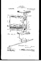
- Figure 1 ront end of an automobile with the near front wheel removed showing the application of the invention
- Fig. 2 is a front View thereof with the front wheels both removed
- Fig.- 3 is a top plan view of the same
- Fig. 4 is a detail perspective view of the connecting rodl of the steering mechanism showingthe arrangement of the levers and shafts for operatively con# necting said rod' with the lamps.
- 1 denotes the annular supporting 'frames 'or rings of the lamps 2.
- the rings or frames 1 are secured in position to support the lamps by fastening plates 8 which are secured to the outer sides of rings and to a suitable portion of the front end of the frame as shown.
- the frames are provided with upper and lower bearing passages 4 and 5.
- One of the lamps is provided. with upper and lower pivot studs 6 which are adapted to pivotally engage passages 4 and 5 of its supportm frame.
- the other lamp is provided'on its upper side with a pivot stud 7 which is adapted to engage the upper pivot wardly project-ing crank arm 8 which is pivotally engaged with and projects through the lower passage 5 in the frame.
- the lower end of the crank arm projects forwardly and is provided with a socket 9 adapted .to receive the pivot pin 10 of a coupling member 11.
- a coupling member 11 On the end of the coupling member 11 are formed apertured ears or lugs between which is pivotally secured one end of a connecting rod 12 the opposite end of which is pivotally connected by a coupling member 13 to the front cross bar 14 of the steering mechanism.
- the opposite ends of the bar 14 are connected to the crank arms 15 of short steering axles 1G of the front wheels.
- One of the axles 16 has formed thereon the usualA operating arm 17 which is connected by an operating rod 18 to the crank arm 19 on the steering shaft as shown.
- the lamps 2 are connected together to move in unison by a connecting rod 20 the opposite ends of which are pivotally connected to brackets 21 arranged on the rear side of the lamps.
- a connecting rod 20 the opposite ends of which are pivotally connected to brackets 21 arranged on the rear side of the lamps.
- a diri ible head light for vehicles comprising rames with lamps pivotally connected thereto, one of the lamps having a downwardly projecting arm bent forwardly at its lower end and having a socket in its terminal, a forked coupling member having' its upper end pivoted to the socket and pling pivoted to its body portion, its I forked end having the other end of the above mentioned rod hinged thereto, braak ets' on the rear faces of the lamps, and av rod having its opposite ends pivoted to the brackets whereby to operate the lamps si multaneously.
Landscapes
- Engineering & Computer Science (AREA)
- Mechanical Engineering (AREA)
- Lighting Device Outwards From Vehicle And Optical Signal (AREA)
Description
J. L. LOWE.
DIRIGIBLE HEADLIGHT.
APPLIOATION FILED Nov 2s, 1910.
Patented Mar. 12, 1912.
Jamal-.Lowe
WMM/.moa
fw flttmmma J. L LOWE.
DIRIGIBLE BEADLIGHT.
' APPLICATION FILED NOV. 29, 1910. 1,0] '9 976, A P atented Mar. 12, 1912.
2 SHEETS-SHEBT 2.
" Y Smau/bof:
@XM/Www 1J amesLL owe if' Mm uw :mams
JAMES L. -LO'W'E, 0F MOORE, MONTANA.
DIRIGIBLE HEADLIGHT.
Specification of Letters Patent.
Patented Mar. 12, 1912.
Application filed November 29, 1910. Serial No. 594,626.
To all whom 'it may concern:
Be it known that I, JAMES L. LOWE, a citizen of the United States, residing at Moore, in the county of Fergus and State of Montana, have invented certain new and useful Improvements .in Dirio'ible Headlights; and I do .declare the following to be a full, clear, and exact description of the invention, such as will enable others skilled in the art'to which it appertains to make and use the same. v
This invention relates to improvements in dirigible head lights for vehicles.
, One object of the invention is to provide a simple and inexpensive means for supporting and operatively connecting the lamps of thehead lights with the steering mec anis'm of the 'vehicle whereby said lamps will be automatically turned in the direction in which the vehicle is steered.
With this and other objects in view, the invention consists of certain novel features ofconstruction, combination and arrangel is aside view of the ment of parts as will be more fully described and particularly pointed out in the appended claim.
In the accompanyin drawings: Figure 1 ront end of an automobile with the near front wheel removed showing the application of the invention; Fig. 2 is a front View thereof with the front wheels both removed; Fig.- 3 is a top plan view of the same; Fig. 4 is a detail perspective view of the connecting rodl of the steering mechanism showingthe arrangement of the levers and shafts for operatively con# necting said rod' with the lamps.
Referring more particularly to the drawings, 1 denotes the annular supporting 'frames 'or rings of the lamps 2. The rings or frames 1 are secured in position to support the lamps by fastening plates 8 which are secured to the outer sides of rings and to a suitable portion of the front end of the frame as shown.
The frames are provided with upper and lower bearing passages 4 and 5. One of the lamps is provided. with upper and lower pivot studs 6 which are adapted to pivotally engage passages 4 and 5 of its supportm frame. The other lamp is provided'on its upper side with a pivot stud 7 which is adapted to engage the upper pivot wardly project-ing crank arm 8 which is pivotally engaged with and projects through the lower passage 5 in the frame.
The lower end of the crank arm projects forwardly and is provided with a socket 9 adapted .to receive the pivot pin 10 of a coupling member 11. On the end of the coupling member 11 are formed apertured ears or lugs between which is pivotally secured one end of a connecting rod 12 the opposite end of which is pivotally connected by a coupling member 13 to the front cross bar 14 of the steering mechanism. The opposite ends of the bar 14 are connected to the crank arms 15 of short steering axles 1G of the front wheels. One of the axles 16 has formed thereon the usualA operating arm 17 which is connected by an operating rod 18 to the crank arm 19 on the steering shaft as shown.
The lamps 2 are connected together to move in unison by a connecting rod 20 the opposite ends of which are pivotally connected to brackets 21 arranged on the rear side of the lamps. By mounting the lamps and pivotally connecting. the same to the steering mechanism of the vehicle as herein shown and described, the lamps will be turned in their supporting frames simul taneously with the operation of the steering mechanism to throw the light in the direction in which the vehicle is steered,
From the foregoing description, taken in connection with the accompanying drawings, the construction and operation of the invention willI be readily understood without requiring a more extended explanation.
Various changes in the form, proportion and the minor details of construction may be resorted to without departing from the principle or sacrificing any of the advantages of this invention, as defined in the appended claim.
Having thus described my invention what I claim is A diri ible head light for vehicles comprising rames with lamps pivotally connected thereto, one of the lamps having a downwardly projecting arm bent forwardly at its lower end and having a socket in its terminal, a forked coupling member having' its upper end pivoted to the socket and pling pivoted to its body portion, its I forked end having the other end of the above mentioned rod hinged thereto, braak ets' on the rear faces of the lamps, and av rod having its opposite ends pivoted to the brackets whereby to operate the lamps si multaneously.
In testimony whereof I have hereunto set my hand in presence lof two subscribing
Priority Applications (1)
| Application Number | Priority Date | Filing Date | Title |
|---|---|---|---|
| US59462610A US1019976A (en) | 1910-11-29 | 1910-11-29 | Dirigible headlight. |
Applications Claiming Priority (1)
| Application Number | Priority Date | Filing Date | Title |
|---|---|---|---|
| US59462610A US1019976A (en) | 1910-11-29 | 1910-11-29 | Dirigible headlight. |
Publications (1)
| Publication Number | Publication Date |
|---|---|
| US1019976A true US1019976A (en) | 1912-03-12 |
Family
ID=3088274
Family Applications (1)
| Application Number | Title | Priority Date | Filing Date |
|---|---|---|---|
| US59462610A Expired - Lifetime US1019976A (en) | 1910-11-29 | 1910-11-29 | Dirigible headlight. |
Country Status (1)
| Country | Link |
|---|---|
| US (1) | US1019976A (en) |
-
1910
- 1910-11-29 US US59462610A patent/US1019976A/en not_active Expired - Lifetime
Similar Documents
| Publication | Publication Date | Title |
|---|---|---|
| US1019976A (en) | Dirigible headlight. | |
| US816696A (en) | Mechanism for vehicle-lanterns. | |
| US987843A (en) | Headlight-controller for vehicles. | |
| US805194A (en) | Lamp or headlight for vehicles. | |
| US1095289A (en) | Dirigible headlight. | |
| US1429113A (en) | Headlight | |
| US1617160A (en) | Dirigible headlight | |
| US1264619A (en) | Automobile-lamp support. | |
| US1346052A (en) | Runner-carrier for motor-vehicles | |
| US702448A (en) | Motor-vehicle. | |
| US1233027A (en) | Dirigible headlight for automobiles. | |
| US939158A (en) | Trackless power-driven vehicle. | |
| US1658534A (en) | Vehicle-headlight mechanism | |
| US1476630A (en) | Headlight-adjusting mechanism | |
| US1241410A (en) | Dirigible headlight. | |
| US1326587A (en) | Dirigible headlight. | |
| US1058835A (en) | Headlight-steering mechanism. | |
| US1163027A (en) | Dirigible automobile-lamp. | |
| US1701789A (en) | Dirigible headlight for automobiles | |
| US1181765A (en) | Dirigible headlight. | |
| US1592425A (en) | Revolving headlight for automobiles | |
| US986966A (en) | Pivot-light. | |
| US1442604A (en) | Dirigible lamp | |
| US1234792A (en) | Dirigible headlight. | |
| US1099217A (en) | Automobile-headlight. |