RELATED APPLICATIONS
This application is the U.S. national phase under § 371 of International Application No. PCT/CN2015/099817 filed Dec. 30, 2015, which claims priority from China Patent Application Serial Number 201510526820.9, filed Aug. 25, 2015. The entire contents of each of which are incorporated by reference.
BACKGROUND
Field of Invention
The present invention relates to a frame assembly and an application thereof. More particularly, the present invention relates to a frame assembly which is applicable to a display device and a display device using the frame assembly.
Description of Related Art
A liquid crystal display mainly includes a backlight module, a liquid crystal display panel and an outer frame. Moreover, a mold frame for carrying the liquid crystal display panel is disposed on the backlight module. After the liquid crystal display panel is disposed on the mold frame, the outer frame is used to fix the mold frame, the liquid crystal display panel and the backlight module, so as to finish assembly of the liquid crystal display.
A common method for fixing the outer frame can be such as locking by screws. However, such method for fixing the outer frame may have many shortcomings. For example, the method of locking by screws may damage the structure of the outer frame and affect its appearance.
SUMMARY
One object of the present invention is to provide a frame assembly and a display device which can be easily processed and have better assembly robustness and appearance.
According to the aforementioned object, a frame assembly is provided. The frame assembly includes a back plate, a first frame and a fixing assembly. The back plate comprises at least one side edge, and the side edge has an extending direction. The first frame is combined with the back plate. The fixing assembly includes at least one first engaging structure, at least one second engaging structure and a fixing member. The first engaging structure is disposed on the at least one side edge of the back plate. The second engaging structure is disposed on at least one side edge of the first frame. The fixing member is inserted into and combined with the at least one first engaging structure and the at least one second engaging structure along the extending direction.
According to an embodiment of the present invention, the aforementioned frame assembly includes a second frame. The back plate is combined between the first frame and the second frame. The fixing assembly further includes at least one third engaging structure disposed on at least one side edge of the second frame. The fixing member is inserted into and combined with the at least one third engaging structure.
According to an embodiment of the present invention, each of the first engaging structure, the second engaging structure and the third engaging structure is an annular structure.
According to an embodiment of the present invention, the aforementioned annular structures are alternately disposed and disposed coaxially with an axis, and the axis is parallel to the extending direction.
According to an embodiment of the present invention, each of the annular structures is an open annular structure or an enclosed annular structure.
According to an embodiment of the present invention, the fixing member includes a head portion and a rod portion connected to the head portion. The rod portion is inserted into the at least one engaging structure, at least one second engaging structure and at least one third engaging structure. An outer profile dimension of the head portion is greater than an inner profile dimension of each of the annular structures.
According to the aforementioned object, a display device is provided. The display device includes the aforementioned frame assembly and a display unit. The display unit is disposed in the frame assembly.
According to an embodiment of the present invention, the aforementioned display unit includes a light guide plate, a light source and a display panel. The light guide plate is disposed on the back plate, in which the light guide plate has a light-incident surface and a light-emitting surface connected to the light-incident surface. The light source is disposed adjacent to the light-incident surface. The display panel is disposed in front of the light-emitting surface.
According to the aforementioned object, another display device is provided. The display device includes a frame assembly and a display unit. The frame assembly includes a first frame, a second frame, a back plate and a fixing assembly. The first frame has at least one side edge. The second frame has at least one side edge, in which the least one side edge of the first frame and the least one side edge of the second frame have an extending direction. The back plate is located between the first frame and the second frame. The fixing assembly includes at least one first engaging structure, at least one second engaging structure and a fixing member. The first engaging structure is disposed on the at least one side edge of the first frame. The second engaging structure is disposed on the at least one side edge of the second frame. The fixing member is inserted into and combined with the at least one first engaging structure and the at least one second engaging structure along the extending direction. The display unit is combined with the back plate of the frame assembly and is located between the first frame and the second frame.
According to an embodiment of the present invention, the aforementioned display unit includes a light guide plate, a light source and a display panel. The light guide plate is disposed on the back plate, in which the light guide plate has a light-incident surface and a light-emitting surface connected to the light-incident surface. The light source is disposed adjacent to the light-incident surface. The display panel is disposed in front of the light-emitting surface.
According to an embodiment of the present invention, one of the first frame and the second frame is engaged and fixed with the back plate.
According to an embodiment of the present invention, the second frame is located behind the back plate of the frame assembly.
According to an embodiment of the present invention, the first frame is located in front of and surrounds the display panel.
According to the aforementioned embodiments of the present invention, the engaging structures are disposed internally in the back plate, the first frame and the second frame, and then the back plate, the first frame and the second frame are jointed together by inserting the fixing member into the engaging structures, thereby greatly reducing the number of the screws and screws holes, and simplifying the structure of the frame assembly and the assembling process thereof, thus making the frame assembling more appealing.
BRIEF DESCRIPTION OF THE DRAWINGS
The invention can be more fully understood by reading the following detailed description of the embodiment, with reference made to the accompanying drawings as follows:
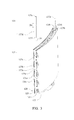
FIG. 1 is a partial cross-sectional view showing a display device in accordance with a first embodiment of the present invention;
FIG. 2 is a schematic exploded view showing a frame assembly in accordance with the first embodiment of the present invention;
FIG. 3 is another schematic exploded view showing the frame assembly in accordance with the first embodiment of the present invention;
FIG. 4 is a schematic structural diagram showing the display device in accordance with the first embodiment of the present invention;
FIG. 5 is a partial enlarged schematic diagram of FIG. 4;
FIG. 6 is a schematic exploded view showing a frame assembly in accordance with a second embodiment of the present invention;
FIG. 7 is another schematic exploded view showing the frame assembly in accordance with the second embodiment of the present invention;
FIG. 8 is a schematic exploded view showing a frame assembly in accordance with a third embodiment of the present invention; and
FIG. 9 is another schematic exploded view showing the frame assembly in accordance with the third embodiment of the present invention.
DETAILED DESCRIPTION
Referring to FIG. 1 to FIG. 3, FIG. 1 is a partial cross-sectional view showing a display device 100 in accordance with a first embodiment of the present invention, and FIG. 2 and FIG. 3 are two schematic exploded views showing a frame assembly 120 in accordance with the first embodiment of the present invention. The display device 100 of the present embodiment mainly includes the frame assembly 120 and a display unit 140. The display unit 140 is disposed in the frame assembly 120. The frame assembly 120 includes a back plate 121, a first frame 123, a second frame 125 and a fixing assembly 127. In the present embodiment, the first frame 123 and the second frame 125 are respectively disposed in front of and behind the back plate 121. The fixing assembly 127 is used to combine and fix the back plate 121, the first frame 123 and the second frame 125 to form a combination. In one example, the first frame 123 can be a front frame, and the second frame 125 can be a back cover.
Referring to FIG. 1, the display unit 140 includes a light guide plate 141, a light source 143 and a display panel 145. The light guide plate 141 is disposed in the back plate 121, and the light guide plate 141 has a light-incident surface 141 a and a light-emitting surface 141 b connected to the light-incident surface 141 a. The light source 143 is also disposed in the back plate 121 and located adjacent to the light-incident surface 141 a of the light guide plate 141. As shown in FIG. 1, the display panel 145 is disposed in front of the light-emitting surface 141 b of the light guide plate 141. In the present embodiments, the first frame 123 is a hollow frame structure and surrounds the display panel 145.
Simultaneously referring to FIG. 2 and FIG. 3, the back plate 121 has a side edge 121 a, and the side edge 121 a has an extending direction D1. The first frame 123 has a side edge 123 a, and the second frame 125 has a side edge 125 a. The side edge 123 a and the side edge 125 a are corresponding to the side edge 121 a of the back plate 121. As shown in FIG. 2 and FIG. 3, the fixing assembly 127 includes at least one first engaging structure 127 a, at least one second engaging structure 127 b, at least one third engaging structure 127 c and a fixing member 127 d. The first engaging structure 127 a is disposed on the side edge 121 a of the back plate 121, the second engaging structure 127 b is disposed on the side edge 123 a of the first frame 123, and the third engaging structure 127 c is disposed on the side edge 125 a of the second frame 125. The fixing member 127 d is inserted into the first engaging structure 127 a, the second engaging structure 127 b and the third engaging structure 127 c, so as to fix the back plate 121, the first frame 123 and the second frame 125 together.
Referring to FIG. 2 and FIG. 3 again, in one embodiment, each of the first engaging structure 127 a, the second engaging structure 127 b and the third engaging structure 127 c is an annular structure, and these annular structures are alternately disposed. When the back plate 121, the first frame 123 and the second frame 125 are stacked together, respective centers of each of the first engaging structure 127 a, the second engaging structure 127 b and the third engaging structure 127 c are located on the same axis A1. In the present embodiment, the axis A1 is parallel to the extending direction D1. In some examples, each of the annular structures can be an open annular structure, such as a C-like structure. In other examples, each of the annular structures can be an enclosed annular structure, such as O-like structure.
Referring to FIG. 3 to FIG. 5, in which FIG. 4 is a schematic structural diagram showing the display device 100 in accordance with the first embodiment of the present invention, and FIG. 5 is a partial enlarged schematic diagram of FIG. 4. As shown in FIG. 3 to FIG. 5, the fixing member 127 d of the present embodiment is an elongated rod. The fixing member 127 d has a head portion 127 e and a rod portion 127 f connected to the head portion 127 e. An outer profile dimension of the head portion 127 e is greater than an inner profile dimension of each of the first engaging structure 127 a, the second engaging structure 127 b and the third engaging structure 127 c. Therefore, after the rod portion 127 f of the fixing member 127 d is inserted into the first engaging structure 127 a of the back plate 121, the second engaging structure 127 b of the first frame 123 and the third engaging structure 127 c of the second frame 125, the head portion 127 e is unable to pass through the first engaging structure 127 a, the second engaging structure 127 b and the third engaging structure 127 c, thus preventing the fixing member 127 d from slipping off, so that the fixing member 127 d can be firmly engaged with the back plate 121, the first frame 123 and the second frame 125.
Referring to FIG. 2 and FIG. 3 again, the back plate 121 has a side edge 121 b opposite to the side edge 121 a, the first frame 123 has a side edge 123 b opposite to the side edge 123 a, and the second frame 125 has a side edge 125 b opposite to the side edge 125 a. The first engaging structure 127 a, the second engaging structure 127 b, the third engaging structure 127 c and the fixing member 127 d of the fixing assembly 127 may also be disposed on the side edges 121 b, 123 b and 125 b, such that two opposite side edges of each of the back plate 121, the first frame 123 and the second frame 125 can be simultaneously fixed to achieve the aforementioned objects.
It is noted that, the “side edges” as used in the aforementioned embodiment which refers to “shorter side edges” of the back plate, the first frame and the second frame is merely used as an example for explanation, and embodiments of the present invention are not limited thereto. In other embodiments, “side edges” also can refer to “longer side edges” of the back plate, the first frame and the second frame. Moreover, the fixing assembly of the present embodiment is not limited to being disposed on both side edges of the combination of the back plate, the first frame and the second frame. In other embodiments, the fixing assembly is disposed on only one side edge of the combination of the back plate, the first frame and the second frame.
Moreover, as shown in FIG. 2 and FIG. 3, both of a size of the first frame 123 and a size of the second frame 125 are approximately greater than the back plate 121, so as to cover the back plate 121. In addition, the first engaging structure 127 a is disposed on an outer side of the side edge 121 a of the back plate 121. The second engaging structure 127 b and the third engaging structure 127 c are respectively disposed on an inner side of the side edge 123 a of the first frame 123 and an inner side of the side edge 125 a of the second frame 125. Therefore, when the back plate 121, the first frame 123 and the second frame 125 are combined with each other, the first engaging structure 127 a and the second engaging structure 127 b can be accepted between the first frame 123 and the second frame 125, thus making the display device 100 look more simple and appealing.
In the present invention, the frame assembly may have different designs. Simultaneously referring to FIG. 6 and FIG. 7, FIG. 6 and FIG. 7 are two schematic exploded views showing a frame assembly 220 in accordance with a second embodiment of the present invention. The frame assembly 220 of the present embodiment includes a back plate 221, a first frame 223, a second frame 225 and a fixing assembly 227. Similarly, the frame assembly 220 of the present invention can be used to accommodate the display unit 140 shown in FIG. 1, so as to make the display device 100 look more appealing and easily processed.
Referring to FIG. 6 and FIG. 7 again, the fixing assembly 227 includes at least one first engaging structure 227 a, at least one second engaging structure 227 b and a fixing member 227 c. The first engaging structure 227 a is disposed on a side edge 223 a of the first frame 223, and the second engaging structure 227 b is disposed on a side edge 225 a of the second frame 225. Similarly, each of the first engaging structure 227 a and the second engaging structure 227 b is an annular structure, and these annular structures are alternately disposed. When the back plate 221, the first frame 223 and the second frame 225 are stacked together, respective centers of each of the first engaging structure 227 a and the second engaging structure 227 b are located on the same axis A2. In the present embodiment, one of the first frame 223 and the second frame 225 is engaged and fixed with the back plate 221. In some examples, the first frame 223 and the second frame 225 can be made of plastic having elasticity itself, which enables the first frame 223 and the second frame 225 to be elastically engaged with the back plate 221. Therefore, by inserting the fixing member 227 c along the axis A2 to the first engaging structure 227 a and the second engaging structure 227 b, the back plate 221, the first frame 223 and the second frame 225 can be firmly engaged together.
As shown in FIG. 6 and FIG. 7, both of a size of the first frame 223 and a size of the second frame 225 are approximately greater than the back plate 221, so as to cover the back plate 221. In addition, the first engaging structure 227 a is disposed on an inner side of the side edge 223 a of the first frame 223. The second engaging structure 227 b is disposed on an inner side of the side edge 225 a of the second frame 225. Therefore, when the back plate 221, the first frame 223 and the second frame 225 are combined with each other, the first engaging structure 227 a and the second engaging structure 227 b can be accepted between the first frame 223 and the second frame 225, thus making the frame assembly 220 look more simple and appealing.
In the present invention, the frame assembly may have different designs. Simultaneously referring to FIG. 8 and FIG. 9, FIG. 8 and FIG. 9 are two schematic exploded views showing a frame assembly 320 in accordance with a third embodiment of the present invention. The frame assembly 320 of the present embodiment includes a back plate 321, a first frame 323, a second frame 325 and a fixing assembly 327. Similarly, the frame assembly 320 of the present invention can be used to accommodate the display unit 140 shown in FIG. 1, so as to make the display device look more appealing and easily processed.
Referring to FIG. 8 and FIG. 9 again, the fixing assembly 327 includes at least one first engaging structure 327 a, at least one second engaging structure 327 b and a fixing member 327 c. The first engaging structure 327 a is disposed on a side edge 321 a of the back plate 321, and the second engaging structure 327 b is disposed on a side edge 325 a of the second frame 325. Similarly, each of the first engaging structure 327 a and the second engaging structure 327 b is an annular structure, and these annular structures are alternately disposed. When the back plate 321, the first frame 323 and the second frame 325 are stacked together, respective centers of each of the first engaging structure 327 a and the second engaging structure 327 b are located on the same axis A3. In the present embodiment, the first frame 323 can be engaged and fixed with the back plate 321 and/or the second frame 325. In assembling process, the fixing member 327 c is first inserted into the first engaging structure 327 a and the second engaging structure 327 b along the axis A3, so as to combine the back plate 321 with the second frame 325. Thereafter, the first frame 323 is engaged on the back plate 321 and the second frame 325 by its elasticity, so that the first frame 223 and the second frame 225 can be firmly engaged together.
Moreover, as shown in FIG. 8 and FIG. 9, both of a size of the first frame 323 and a size of the second frame 325 are approximately greater than the back plate 321, so as to cover the back plate 321. In addition, the first engaging structure 327 a is disposed on an outer side of the side edge 321 a of the back plate 321, and the second engaging structure 327 b is disposed on an inner side of the side edge 325 a of the second frame 325. Therefore, when the back plate 321, the first frame 323 and the second frame 325 are combined with each other, the first engaging structure 327 a and the second engaging structure 327 b can be accepted between the first frame 323 and the second frame 325, thus making the frame assembly 320 look more simple and appealing.
It is noted that the first engaging structure 327 a which is disposed on the back plate 321 and the second engaging structure 327 b which is disposed on the second frame 325 are merely used as an example for explanation, and embodiments of the present invention are not limited thereto. In other embodiments, the second engaging structure 327 b can be disposed on the first frame 323, and the second frame 325 can be elastically engaged with the first frame 323 and/or the back plate 321, thus achieving the aforementioned objects.
It can be known from the aforementioned embodiments of the present invention that, the engaging structures are disposed internally in the back plate, the first frame and the second frame, and then the back plate, the first frame and the second frame are jointed together by inserting the fixing member into the engaging structures, thereby greatly reducing the number of the screws and screws holes, and simplifying the structure of the frame assembly and the assembling process thereof, thus making the frame assembling more appealing.
Although the present invention has been described in considerable detail with reference to certain embodiments thereof, other embodiments are possible. Therefore, the spirit and scope of the appended claims should not be limited to the description of the embodiments contained herein. It will be apparent to those skilled in the art that various modifications and variations can be made to the structure of the present invention without departing from the scope or spirit of the invention. In view of the foregoing, it is intended that the present invention cover modifications and variations of this invention provided they fall within the scope of the following claims.