US10197069B2 - Outer airseal for gas turbine engine - Google Patents
Outer airseal for gas turbine engine Download PDFInfo
- Publication number
- US10197069B2 US10197069B2 US14/947,494 US201514947494A US10197069B2 US 10197069 B2 US10197069 B2 US 10197069B2 US 201514947494 A US201514947494 A US 201514947494A US 10197069 B2 US10197069 B2 US 10197069B2
- Authority
- US
- United States
- Prior art keywords
- airseal
- cavity
- compressor
- turbine engine
- gas turbine
- Prior art date
- Legal status (The legal status is an assumption and is not a legal conclusion. Google has not performed a legal analysis and makes no representation as to the accuracy of the status listed.)
- Active, expires
Links
Images


Classifications
-
- F—MECHANICAL ENGINEERING; LIGHTING; HEATING; WEAPONS; BLASTING
- F04—POSITIVE - DISPLACEMENT MACHINES FOR LIQUIDS; PUMPS FOR LIQUIDS OR ELASTIC FLUIDS
- F04D—NON-POSITIVE-DISPLACEMENT PUMPS
- F04D29/00—Details, component parts, or accessories
- F04D29/40—Casings; Connections of working fluid
- F04D29/52—Casings; Connections of working fluid for axial pumps
- F04D29/522—Casings; Connections of working fluid for axial pumps especially adapted for elastic fluid pumps
- F04D29/526—Details of the casing section radially opposing blade tips
-
- F—MECHANICAL ENGINEERING; LIGHTING; HEATING; WEAPONS; BLASTING
- F01—MACHINES OR ENGINES IN GENERAL; ENGINE PLANTS IN GENERAL; STEAM ENGINES
- F01D—NON-POSITIVE DISPLACEMENT MACHINES OR ENGINES, e.g. STEAM TURBINES
- F01D11/00—Preventing or minimising internal leakage of working-fluid, e.g. between stages
- F01D11/08—Preventing or minimising internal leakage of working-fluid, e.g. between stages for sealing space between rotor blade tips and stator
- F01D11/12—Preventing or minimising internal leakage of working-fluid, e.g. between stages for sealing space between rotor blade tips and stator using a rubstrip, e.g. erodible. deformable or resiliently-biased part
- F01D11/122—Preventing or minimising internal leakage of working-fluid, e.g. between stages for sealing space between rotor blade tips and stator using a rubstrip, e.g. erodible. deformable or resiliently-biased part with erodable or abradable material
-
- F—MECHANICAL ENGINEERING; LIGHTING; HEATING; WEAPONS; BLASTING
- F01—MACHINES OR ENGINES IN GENERAL; ENGINE PLANTS IN GENERAL; STEAM ENGINES
- F01D—NON-POSITIVE DISPLACEMENT MACHINES OR ENGINES, e.g. STEAM TURBINES
- F01D11/00—Preventing or minimising internal leakage of working-fluid, e.g. between stages
- F01D11/08—Preventing or minimising internal leakage of working-fluid, e.g. between stages for sealing space between rotor blade tips and stator
- F01D11/14—Adjusting or regulating tip-clearance, i.e. distance between rotor-blade tips and stator casing
- F01D11/16—Adjusting or regulating tip-clearance, i.e. distance between rotor-blade tips and stator casing by self-adjusting means
- F01D11/18—Adjusting or regulating tip-clearance, i.e. distance between rotor-blade tips and stator casing by self-adjusting means using stator or rotor components with predetermined thermal response, e.g. selective insulation, thermal inertia, differential expansion
-
- F—MECHANICAL ENGINEERING; LIGHTING; HEATING; WEAPONS; BLASTING
- F01—MACHINES OR ENGINES IN GENERAL; ENGINE PLANTS IN GENERAL; STEAM ENGINES
- F01D—NON-POSITIVE DISPLACEMENT MACHINES OR ENGINES, e.g. STEAM TURBINES
- F01D11/00—Preventing or minimising internal leakage of working-fluid, e.g. between stages
- F01D11/08—Preventing or minimising internal leakage of working-fluid, e.g. between stages for sealing space between rotor blade tips and stator
- F01D11/14—Adjusting or regulating tip-clearance, i.e. distance between rotor-blade tips and stator casing
- F01D11/20—Actively adjusting tip-clearance
- F01D11/24—Actively adjusting tip-clearance by selectively cooling-heating stator or rotor components
-
- F—MECHANICAL ENGINEERING; LIGHTING; HEATING; WEAPONS; BLASTING
- F04—POSITIVE - DISPLACEMENT MACHINES FOR LIQUIDS; PUMPS FOR LIQUIDS OR ELASTIC FLUIDS
- F04D—NON-POSITIVE-DISPLACEMENT PUMPS
- F04D29/00—Details, component parts, or accessories
- F04D29/08—Sealings
- F04D29/16—Sealings between pressure and suction sides
- F04D29/161—Sealings between pressure and suction sides especially adapted for elastic fluid pumps
- F04D29/164—Sealings between pressure and suction sides especially adapted for elastic fluid pumps of an axial flow wheel
-
- F—MECHANICAL ENGINEERING; LIGHTING; HEATING; WEAPONS; BLASTING
- F04—POSITIVE - DISPLACEMENT MACHINES FOR LIQUIDS; PUMPS FOR LIQUIDS OR ELASTIC FLUIDS
- F04D—NON-POSITIVE-DISPLACEMENT PUMPS
- F04D29/00—Details, component parts, or accessories
- F04D29/26—Rotors specially for elastic fluids
- F04D29/32—Rotors specially for elastic fluids for axial flow pumps
- F04D29/321—Rotors specially for elastic fluids for axial flow pumps for axial flow compressors
-
- F—MECHANICAL ENGINEERING; LIGHTING; HEATING; WEAPONS; BLASTING
- F05—INDEXING SCHEMES RELATING TO ENGINES OR PUMPS IN VARIOUS SUBCLASSES OF CLASSES F01-F04
- F05D—INDEXING SCHEME FOR ASPECTS RELATING TO NON-POSITIVE-DISPLACEMENT MACHINES OR ENGINES, GAS-TURBINES OR JET-PROPULSION PLANTS
- F05D2220/00—Application
- F05D2220/30—Application in turbines
- F05D2220/32—Application in turbines in gas turbines
Definitions
- This disclosure relates to a gas turbine engine, and more particularly to gaspath leakage seals for gas turbine engines.
- Gas turbine engines such as those used to power modern commercial and military aircrafts, generally include a compressor section to pressurize an airflow, a combustor section for burning hydrocarbon fuel in the presence of the pressurized air, and a turbine section to extract energy from the resultant combustion gases.
- the airflow flows along a gaspath through the gas turbine engine.
- the gas turbine engine includes a plurality of rotors arranged along an axis of rotation of the gas turbine engine.
- the rotors are positioned in a case, with the rotors and case having designed clearances between the case and tips of rotor blades of the rotors. It is desired to maintain the clearances within a selected range during operation of the gas turbine engine as deviation from the selected range can have a negative effect on gas turbine engine performance.
- the case typically includes an outer airseal located in the case opposite the rotor blade tip to aid in maintaining the clearances within the selected range.
- the outer airseals are mounted in the case, but often result in high heat transfer from the gaspath up into the flanges of the case. This results in faster case response than is often desirable, resulting in clearances outside of the selected range. Mass is often added to the case to slow the case response, but has limited effectiveness, and also increases the weight of the gas turbine engine.
- an airseal for sealing between a rotating component and a stationary component of a turbine engine includes a sealing surface defining a spacing between the airseal and a rotating component of the turbine engine and a mounting flange to secure the airseal to a stationary component of the turbine engine.
- An airseal body extends between the sealing surface and the mounting flange. The airseal body includes a cavity configured to absorb thermal energy transferred into the airseal from a flowpath of the turbine engine.
- the cavity extends circumferentially around a turbine engine axis.
- the cavity has a cavity axial length greater than a cavity radial width.
- a vent extends from the cavity through the airseal body and is configured to relieve air pressure in the cavity.
- the airseal includes a first airseal portion including a first cavity portion and a second airseal portion including a second cavity portion.
- An attachment secures the first airseal portion to the second airseal portion.
- the attachment is a braze or weld.
- a compressor assembly for a turbine engine includes a compressor rotor rotatable about a compressor axis, the compressor rotor including a compressor disc and a plurality of compressor blades extending radially outwardly from the compressor disc.
- a compressor case is located radially outboard of the compressor rotor.
- An airseal is positioned between the compressor case and the compressor blades and includes a sealing surface defining a spacing between the airseal and the plurality of rotor blades and a mounting flange to secure the airseal to the compressor case.
- An airseal body extends between the sealing surface and the mounting flange. The airseal body includes a cavity configured to absorb thermal energy transferred into the airseal from a flowpath of the turbine engine.
- the cavity extends circumferentially around the compressor axis.
- the cavity has a cavity axial length greater than a cavity radial width.
- a vent extends from the cavity through the airseal body and is configured to relieve air pressure in the cavity.
- the airseal includes a first airseal portion including a first cavity portion and a second airseal portion including a second cavity portion.
- An attachment secures the first airseal portion to the second airseal portion.
- the attachment is a braze or weld.
- a gas turbine engine in yet another embodiment, includes a rotating component and a stationary component located radially outboard of the rotating component.
- An airseal is located between the stationary component and the rotating component and includes a sealing surface defining a spacing between the airseal and the rotating component and a mounting flange to secure the airseal to the stationary component.
- An airseal body extends between the sealing surface and the mounting flange. The airseal body includes a cavity configured to absorb thermal energy transferred into the airseal from a flowpath of the gas turbine engine.
- the cavity extends circumferentially around a gas turbine engine axis.
- the cavity has a cavity axial length greater than a cavity radial width.
- a vent extends from the cavity through the airseal body and is configured to relieve air pressure in the cavity.
- the airseal includes a first airseal portion including a first cavity portion and a second airseal portion including a second cavity portion.
- An attachment secures the first airseal portion to the second airseal portion.
- the attachment is a braze or weld.
- the rotating component is a compressor rotor including a compressor disc and a plurality of compressor blades extending radially outwardly from the compressor disc, and the airseal is positioned between the stationary component and the compressor blades.
- the mounting flange is configured to secure the airseal to a compressor case.
- FIG. 1 illustrates a schematic cross-sectional view of an embodiment of a gas turbine engine
- FIG. 2 illustrates a schematic cross-sectional view of an embodiment of a compressor of a gas turbine engine
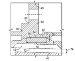
- FIG. 3 illustrates an embodiment of an outer airseal for a gas turbine engine
- FIG. 4 illustrates another embodiment of an outer airseal for a gas turbine engine.
- FIG. 1 is a schematic illustration of a gas turbine engine 10 .
- the gas turbine engine generally has a fan 12 through which ambient air is propelled in the direction of arrow 14 , a compressor 16 for pressurizing the air received from the fan 12 and a combustor 18 wherein the compressed air is mixed with fuel and ignited for generating combustion gases.
- the gas turbine engine 10 further comprises a turbine section 20 for extracting energy from the combustion gases. Fuel is injected into the combustor 18 of the gas turbine engine 10 for mixing with the compressed air from the compressor 16 and ignition of the resultant mixture.
- the fan 12 , compressor 16 , combustor 18 , and turbine 20 are typically all concentric about a common central longitudinal axis of the gas turbine engine 10 .
- the turbine 20 includes one or more turbine stators 22 and one or more turbine rotors 24 .
- the compressor 16 includes one or more compressor rotors 26 and one or more compressor stators 28 . It is to be appreciated that while description below relates to compressors 16 and compressor rotors 26 , one skilled in the art will readily appreciate that the present disclosure may be utilized with respect to turbine rotors 24 .
- the compressor 16 includes a compressor case 30 , in which the compressor rotors 26 are arranged along an engine axis 32 about which the compressor rotors 26 rotate.
- Each compressor rotor 26 includes a rotor disc 34 with a plurality of rotor blades 36 extending radially outwardly from the rotor disc 34 .
- An outer airseal 38 is located in the compressor case 30 radially between a rotor blade tip 40 and an inner case surface 42 .
- the outer airseal 38 includes a rub strip 44 (see FIG. 3 ) configured to abrade in the event of contact with the rotor blade tip 40 .
- the outer airseal 38 extends circumferentially around the compressor rotor 26 , and may be a continuous ring or a plurality of outer airseal segments arranged in a ring.
- the outer airseal 38 extends circumferentially around the compressor rotor 26 , and may be a continuous ring or a plurality of outer airseal segments arranged in a ring.
- the outer airseal 38 includes a rub strip 44 configured to abrade in the event of contact with the rotor blade tip 40 .
- the outer airseal 38 includes an airseal body 46 supportive of the rub strip 44 at a sealing surface 72 .
- the rub strip 44 and sealing surface 72 define a clearance 74 between the outer airseal 38 and the rotor blade tip 40 .
- a mounting flange 48 positions the airseal 38 and secures the airseal 38 in the compressor case 30 via, for example, bolts or other fastening components (not shown). It is desired to control thermal energy transfer or conduction from a gaspath 50 (shown in FIG. 2 ) of the gas turbine engine 10 to the compressor case 30 , since such thermal energy transfer has an effect on the clearance 74 between the rotor blade tip 40 and the outer airseal 38 , which in turn has an effect on gas turbine engine 10 performance.
- the outer airseal 38 includes a thermal cavity 54 positioned in the airseal body 46 .
- the thermal cavity 54 is an opening at least semi enclosed in the airseal body 46 and extending circumferentially about the engine axis 32 .
- the thermal cavity 54 has a cavity length 56 extending along a direction parallel to the engine axis 32 and a cavity width 58 extending in a radial direction.
- the thermal cavity 54 illustrated has an aspect ratio of cavity length 56 to cavity width 58 greater than one and has an oval-shaped cross-section. It is to be appreciated, however, that the thermal cavity may have other cross-sectional shapes such as, for example, circular, elliptical or irregular. Further, in some configurations the thermal cavity 54 may have a varying cross-sectional shape around the circumference of the engine 10 .
- the thermal cavity 54 acts to prevent or slow a flow of thermal energy from the gas path 50 through the outer airseal 38 to the compressor case 30 .
- Thermal energy flowing through the outer airseal 38 is transferred to the air in the thermal cavity 54 , thus reducing the thermal energy flow through the outer airseal 38 .
- This thermal energy transfer increases a pressure of the air in the thermal cavity 54 , thus one or more vents 62 are provided to allow airflow to escape the thermal cavity 54 to relieve the pressure in the thermal cavity 54 .
- the vent 62 is located at an outer surface of the airseal body 46 opposite the rub strip 44 .
- the outer airseal 38 is manufactured in two or more pieces, then joined together to produce the outer airseal 38 configuration with the thermal cavity 54 .
- a radially inboard airseal portion 64 of the outer airseal 38 is formed by, for example, machining, and includes a radially inboard cavity portion 66 .
- a radially outboard airseal portion 68 is formed separately and includes a radially outboard cavity portion 70 .
- the radially inboard airseal portion 64 and radially outboard airseal portion 68 are then joined by, for example, brazing or welding, into a single outer airseal 38 including the thermal cavity 54 .
- the outer airseal 38 may be fabricated in other ways, for example, by separately forming an axially upstream portion containing an axially upstream cavity portion and an axially downstream portion having an axially downstream cavity portion, then joining the two.
- other technologies may be utilized in forming of the outer airseal 38 , such as casting or additive manufacturing methods such as 3D printing.
- the outer airseal 38 with thermal cavity 54 reduces the need to add mass to case flanges to slow thermal response of the case, thus reducing the mass of the case. Further, utilization of the outer airseal 38 reduces thermal gradients in the outer airseal 38 and in the compressor case 30 , so low cycle fatigue life in the components is extended. Additionally, the outer airseal 38 with thermal cavity 54 reduces sensitivity to gaspath fluctuations or uncertainty during, for example, transient operation of the gas turbine engine 10 .
Landscapes
- Engineering & Computer Science (AREA)
- Mechanical Engineering (AREA)
- General Engineering & Computer Science (AREA)
- Structures Of Non-Positive Displacement Pumps (AREA)
Abstract
Description
Claims (17)
Priority Applications (2)
| Application Number | Priority Date | Filing Date | Title |
|---|---|---|---|
| US14/947,494 US10197069B2 (en) | 2015-11-20 | 2015-11-20 | Outer airseal for gas turbine engine |
| EP16195658.6A EP3170990B1 (en) | 2015-11-20 | 2016-10-26 | Outer airseal for gas turbine engine |
Applications Claiming Priority (1)
| Application Number | Priority Date | Filing Date | Title |
|---|---|---|---|
| US14/947,494 US10197069B2 (en) | 2015-11-20 | 2015-11-20 | Outer airseal for gas turbine engine |
Publications (2)
| Publication Number | Publication Date |
|---|---|
| US20170146024A1 US20170146024A1 (en) | 2017-05-25 |
| US10197069B2 true US10197069B2 (en) | 2019-02-05 |
Family
ID=57206117
Family Applications (1)
| Application Number | Title | Priority Date | Filing Date |
|---|---|---|---|
| US14/947,494 Active 2036-11-17 US10197069B2 (en) | 2015-11-20 | 2015-11-20 | Outer airseal for gas turbine engine |
Country Status (2)
| Country | Link |
|---|---|
| US (1) | US10197069B2 (en) |
| EP (1) | EP3170990B1 (en) |
Families Citing this family (1)
| Publication number | Priority date | Publication date | Assignee | Title |
|---|---|---|---|---|
| US10315249B2 (en) | 2016-07-29 | 2019-06-11 | United Technologies Corporation | Abradable material feedstock and methods and apparatus for manufacture |
Citations (14)
| Publication number | Priority date | Publication date | Assignee | Title |
|---|---|---|---|---|
| US3825364A (en) * | 1972-06-09 | 1974-07-23 | Gen Electric | Porous abradable turbine shroud |
| US4468168A (en) * | 1981-11-16 | 1984-08-28 | S.N.E.C.M.A. | Air-cooled annular friction and seal device for turbine or compressor impeller blade system |
| US4527385A (en) | 1983-02-03 | 1985-07-09 | Societe Nationale d'Etude et Je Construction de Moteurs d'Aviation "S.N.E.C.M.A." | Sealing device for turbine blades of a turbojet engine |
| US4679981A (en) * | 1984-11-22 | 1987-07-14 | S.N.E.C.M.A. | Turbine ring for a gas turbine engine |
| US5330321A (en) * | 1992-05-19 | 1994-07-19 | Rolls Royce Plc | Rotor shroud assembly |
| US5584651A (en) * | 1994-10-31 | 1996-12-17 | General Electric Company | Cooled shroud |
| US5993150A (en) * | 1998-01-16 | 1999-11-30 | General Electric Company | Dual cooled shroud |
| EP1001140A2 (en) | 1998-11-13 | 2000-05-17 | General Electric Company | Blade containing turbine shroud |
| US7597533B1 (en) * | 2007-01-26 | 2009-10-06 | Florida Turbine Technologies, Inc. | BOAS with multi-metering diffusion cooling |
| US7665962B1 (en) * | 2007-01-26 | 2010-02-23 | Florida Turbine Technologies, Inc. | Segmented ring for an industrial gas turbine |
| US20110085900A1 (en) * | 2008-05-28 | 2011-04-14 | Mtu Aero Engines Gmbh | Housing for a compressor of a gas turbine, compressor, and method for producing a housing segment of a compressor housing |
| US20130170963A1 (en) * | 2012-01-04 | 2013-07-04 | United Technologies Corporation | Hybrid blade outer air seal for gas turbine engine |
| WO2014168804A1 (en) | 2013-04-12 | 2014-10-16 | United Technologies Corporation | Blade outer air seal with secondary air sealing |
| WO2015102702A2 (en) | 2013-10-07 | 2015-07-09 | United Technologies Corporation | Tailored thermal control system for gas turbine engine blade outer air seal array |
-
2015
- 2015-11-20 US US14/947,494 patent/US10197069B2/en active Active
-
2016
- 2016-10-26 EP EP16195658.6A patent/EP3170990B1/en active Active
Patent Citations (14)
| Publication number | Priority date | Publication date | Assignee | Title |
|---|---|---|---|---|
| US3825364A (en) * | 1972-06-09 | 1974-07-23 | Gen Electric | Porous abradable turbine shroud |
| US4468168A (en) * | 1981-11-16 | 1984-08-28 | S.N.E.C.M.A. | Air-cooled annular friction and seal device for turbine or compressor impeller blade system |
| US4527385A (en) | 1983-02-03 | 1985-07-09 | Societe Nationale d'Etude et Je Construction de Moteurs d'Aviation "S.N.E.C.M.A." | Sealing device for turbine blades of a turbojet engine |
| US4679981A (en) * | 1984-11-22 | 1987-07-14 | S.N.E.C.M.A. | Turbine ring for a gas turbine engine |
| US5330321A (en) * | 1992-05-19 | 1994-07-19 | Rolls Royce Plc | Rotor shroud assembly |
| US5584651A (en) * | 1994-10-31 | 1996-12-17 | General Electric Company | Cooled shroud |
| US5993150A (en) * | 1998-01-16 | 1999-11-30 | General Electric Company | Dual cooled shroud |
| EP1001140A2 (en) | 1998-11-13 | 2000-05-17 | General Electric Company | Blade containing turbine shroud |
| US7597533B1 (en) * | 2007-01-26 | 2009-10-06 | Florida Turbine Technologies, Inc. | BOAS with multi-metering diffusion cooling |
| US7665962B1 (en) * | 2007-01-26 | 2010-02-23 | Florida Turbine Technologies, Inc. | Segmented ring for an industrial gas turbine |
| US20110085900A1 (en) * | 2008-05-28 | 2011-04-14 | Mtu Aero Engines Gmbh | Housing for a compressor of a gas turbine, compressor, and method for producing a housing segment of a compressor housing |
| US20130170963A1 (en) * | 2012-01-04 | 2013-07-04 | United Technologies Corporation | Hybrid blade outer air seal for gas turbine engine |
| WO2014168804A1 (en) | 2013-04-12 | 2014-10-16 | United Technologies Corporation | Blade outer air seal with secondary air sealing |
| WO2015102702A2 (en) | 2013-10-07 | 2015-07-09 | United Technologies Corporation | Tailored thermal control system for gas turbine engine blade outer air seal array |
Non-Patent Citations (1)
| Title |
|---|
| European Search Report and Written Opinion; International Application No. 16195658.6; International Filing Date: Oct. 26, 2016; dated Apr. 6, 2017; 7 pages. |
Also Published As
| Publication number | Publication date |
|---|---|
| US20170146024A1 (en) | 2017-05-25 |
| EP3170990A1 (en) | 2017-05-24 |
| EP3170990B1 (en) | 2019-07-17 |
Similar Documents
| Publication | Publication Date | Title |
|---|---|---|
| US9238977B2 (en) | Turbine shroud mounting and sealing arrangement | |
| JP6134538B2 (en) | Seal assembly for use in rotating machinery and method of assembling rotating machinery | |
| US20110192166A1 (en) | Outlet guide vane structure | |
| US9394915B2 (en) | Seal land for static structure of a gas turbine engine | |
| US9657642B2 (en) | Turbine sections of gas turbine engines with dual use of cooling air | |
| EP2964898B1 (en) | Gas turbine engine with soft mounted pre-swirl nozzle | |
| US9506367B2 (en) | Blade outer air seal having inward pointing extension | |
| JP6143523B2 (en) | Turbine shroud assembly and method of forming the same | |
| EP3090140B1 (en) | Blade outer air seal with secondary air sealing | |
| US20160040547A1 (en) | Blade outer air seal with secondary air sealing | |
| US9404376B2 (en) | Sealing component for reducing secondary airflow in a turbine system | |
| JP2017141821A (en) | Centrifugal compressor assembly for use in turbine engine and method of assembly thereof | |
| US20180230839A1 (en) | Turbine engine shroud assembly | |
| US20140241857A1 (en) | Flow diverter to redirect secondary flow | |
| US10655481B2 (en) | Cover plate for rotor assembly of a gas turbine engine | |
| US11098605B2 (en) | Rim seal arrangement | |
| US10138746B2 (en) | Gas turbine engine flow control device | |
| US10746033B2 (en) | Gas turbine engine component | |
| US10197069B2 (en) | Outer airseal for gas turbine engine | |
| US10570767B2 (en) | Gas turbine engine with a cooling fluid path | |
| US20180106161A1 (en) | Turbine shroud segment | |
| EP3130751B1 (en) | Apparatus and method for cooling the rotor of a gas turbine | |
| US10443426B2 (en) | Blade outer air seal with integrated air shield |
Legal Events
| Date | Code | Title | Description |
|---|---|---|---|
| AS | Assignment |
Owner name: UNITED TECHNOLOGIES CORPORATION, CONNECTICUT Free format text: ASSIGNMENT OF ASSIGNORS INTEREST;ASSIGNORS:LESLIE, NICHOLAS R.;ROGERS, MARK J.;RIOUX, PHILIP ROBERT;SIGNING DATES FROM 20151119 TO 20151120;REEL/FRAME:037103/0203 |
|
| STCF | Information on status: patent grant |
Free format text: PATENTED CASE |
|
| AS | Assignment |
Owner name: RAYTHEON TECHNOLOGIES CORPORATION, MASSACHUSETTS Free format text: CHANGE OF NAME;ASSIGNOR:UNITED TECHNOLOGIES CORPORATION;REEL/FRAME:054062/0001 Effective date: 20200403 |
|
| AS | Assignment |
Owner name: RAYTHEON TECHNOLOGIES CORPORATION, CONNECTICUT Free format text: CORRECTIVE ASSIGNMENT TO CORRECT THE AND REMOVE PATENT APPLICATION NUMBER 11886281 AND ADD PATENT APPLICATION NUMBER 14846874. TO CORRECT THE RECEIVING PARTY ADDRESS PREVIOUSLY RECORDED AT REEL: 054062 FRAME: 0001. ASSIGNOR(S) HEREBY CONFIRMS THE CHANGE OF ADDRESS;ASSIGNOR:UNITED TECHNOLOGIES CORPORATION;REEL/FRAME:055659/0001 Effective date: 20200403 |
|
| MAFP | Maintenance fee payment |
Free format text: PAYMENT OF MAINTENANCE FEE, 4TH YEAR, LARGE ENTITY (ORIGINAL EVENT CODE: M1551); ENTITY STATUS OF PATENT OWNER: LARGE ENTITY Year of fee payment: 4 |
|
| AS | Assignment |
Owner name: RTX CORPORATION, CONNECTICUT Free format text: CHANGE OF NAME;ASSIGNOR:RAYTHEON TECHNOLOGIES CORPORATION;REEL/FRAME:064714/0001 Effective date: 20230714 |