US1019683A - Automatic plate-valve. - Google Patents
Automatic plate-valve. Download PDFInfo
- Publication number
- US1019683A US1019683A US1910579144A US1019683A US 1019683 A US1019683 A US 1019683A US 1910579144 A US1910579144 A US 1910579144A US 1019683 A US1019683 A US 1019683A
- Authority
- US
- United States
- Prior art keywords
- valve
- plate
- strip
- automatic plate
- seat
- Prior art date
- Legal status (The legal status is an assumption and is not a legal conclusion. Google has not performed a legal analysis and makes no representation as to the accuracy of the status listed.)
- Expired - Lifetime
Links
- 238000005452 bending Methods 0.000 description 2
- 208000001848 dysentery Diseases 0.000 description 2
- 239000007789 gas Substances 0.000 description 2
- 239000007788 liquid Substances 0.000 description 2
- 239000000463 material Substances 0.000 description 2
- 239000002184 metal Substances 0.000 description 2
- 230000006835 compression Effects 0.000 description 1
- 238000007906 compression Methods 0.000 description 1
- 230000007547 defect Effects 0.000 description 1
- 239000013013 elastic material Substances 0.000 description 1
- 230000000266 injurious effect Effects 0.000 description 1
- 230000000284 resting effect Effects 0.000 description 1
Images
Classifications
-
- F—MECHANICAL ENGINEERING; LIGHTING; HEATING; WEAPONS; BLASTING
- F04—POSITIVE - DISPLACEMENT MACHINES FOR LIQUIDS; PUMPS FOR LIQUIDS OR ELASTIC FLUIDS
- F04B—POSITIVE-DISPLACEMENT MACHINES FOR LIQUIDS; PUMPS
- F04B39/00—Component parts, details, or accessories, of pumps or pumping systems specially adapted for elastic fluids, not otherwise provided for in, or of interest apart from, groups F04B25/00 - F04B37/00
- F04B39/10—Adaptations or arrangements of distribution members
- F04B39/102—Adaptations or arrangements of distribution members the members being disc valves
-
- Y—GENERAL TAGGING OF NEW TECHNOLOGICAL DEVELOPMENTS; GENERAL TAGGING OF CROSS-SECTIONAL TECHNOLOGIES SPANNING OVER SEVERAL SECTIONS OF THE IPC; TECHNICAL SUBJECTS COVERED BY FORMER USPC CROSS-REFERENCE ART COLLECTIONS [XRACs] AND DIGESTS
- Y10—TECHNICAL SUBJECTS COVERED BY FORMER USPC
- Y10T—TECHNICAL SUBJECTS COVERED BY FORMER US CLASSIFICATION
- Y10T137/00—Fluid handling
- Y10T137/7722—Line condition change responsive valves
- Y10T137/7837—Direct response valves [i.e., check valve type]
- Y10T137/7879—Resilient material valve
- Y10T137/7887—Center flexing strip
Definitions
- the strip-shaped plate is firmly clamped at one end while its other end is mounted displaceable longitudinally in order to enable the valve plate to bendupward.
- This known arrangement has the material disadvantage that the two ends of the plate are subjected to bending stresses and stresses due to axial compression which impair the durability of the plate, particularly at the fixed end, and unavoidably cause the plate to fracture. Further, the ready movability of the valve. is imparted in consequence of the ends of the plate bending.
- a primary object of my invention is to provide 'a plate-valve to which the defects described above are not attached, and which is particularly adapted for use in pumps for conveying gases and liquids
- Figure 1 is a longitudinal section through the closed valve and Fig. 2 a like section throughthe open valve;
- Fig. 3 is a crosss'ection in the line AB in Fig. 1, while
- Fig. 4 is a plan view of the plate only.
- an elastic, thin, metal strip a of constant section rests. on the valve seat a which is provided with one or more slotsb.
- a cap or arrester d having a recess 6 ofarc-shaped sect-ion whose crown is on .the center line AB and exactly determines the form of arc of the plate 0 when it is bent upwardly by the flowing medium.
- Flat recesses f are provided in the cap or arrester, and-allow the ends of the plates the very little playrequired for their movement and assure their correct position relatively to the seat.
- I may make the plate broader in the center in the event of greater section of valve being requisite with a givenlengt-h; also, I may arrange several plates superposed or beside one another for obtalning larger connected systems of valves.
- the subject-matter of my invention can be employed equally well both as a pressure 4 and as a suction valve,
- the scope of my invention is not departed from when the material of'the valve or plate is made of some other elastic material instead of metal, according to the nature of the medium which is supplied in each instance, or when the subject-matter of my invention is employed" for any other purposes than for pumps for conveying gases and liquids.
- An automatic plate-valve of the type described comprising in combination a valve-seat havin recesses with inclined faces, a thin elastic plate or strip extending into said recesses, and a cap or'arrester having a recess of arc-shaped section holding the plate or strip on the valve seat and e29 the valve-seat and exactly determining the upward movement pt the same, substantially as shown.
Landscapes
- Engineering & Computer Science (AREA)
- Mechanical Engineering (AREA)
- General Engineering & Computer Science (AREA)
- Check Valves (AREA)
Description
1%., MEYER. AUTOMATIC PLATE VALVE.
APPLICATION FILED AUG. 26, 1910.
1,019,683. Patented Mar. 5, 1912.
k 4 A i a h I I 31 1 92 I ROBERT MEYER, OF M'ULHEIM-RUHR, GERMANY.
AUTOMATIC PLATE-VALVE.
Specification of Letters Yatent.
Application filed August 26, 1910. Serial No. 579,144REISSUED Patented Mar. 5, 1912.
To all whom it may concern:-
Be it known that I, ROBERT MEYER, a subject of the German Emperor, and residing at Miilheim-Ruhr, Germany, have invented certain new and useful Improvements in Automatic Plate-Valves, of which the following is a specification.
My inventlon relates to -'automatic platevalves, in which the valve plate consists of a simple strip-shaped leaf spring of constant section which lies extended on the valve seat, is weakened neither by holes nor slots, and becomes =bent upwardly by the flowin medium. In the Well 'known valves 0 this type the strip-shaped plate is firmly clamped at one end while its other end is mounted displaceable longitudinally in order to enable the valve plate to bendupward. This known arrangement has the material disadvantage that the two ends of the plate are subjected to bending stresses and stresses due to axial compression which impair the durability of the plate, particularly at the fixed end, and unavoidably cause the plate to fracture. Further, the ready movability of the valve. is imparted in consequence of the ends of the plate bending.
. A primary object of my invention is to provide 'a plate-valve to which the defects described above are not attached, and which is particularly adapted for use in pumps for conveying gases and liquids To this end, I mount the valve-plate in such manneron the valve seat that it can bend upward the intended height without being subjected at any place to the least lateral flexture or excessive transverse stress. and without the departing from the normal bending-line.
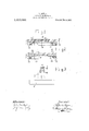
One illustrative embodiment of my invention is represented by way of example in the accompanying drawing, wherein:-
Figure 1 is a longitudinal section through the closed valve and Fig. 2 a like section throughthe open valve; Fig. 3 is a crosss'ection in the line AB in Fig. 1, while Fig. 4 is a plan view of the plate only.
Referring to the drawing, an elastic, thin, metal strip a of constant section rests. on the valve seat a which is provided with one or more slotsb.- Above the valve seat is arranged in well-known manner a cap or arrester d having a recess 6 ofarc-shaped sect-ion whose crown is on .the center line AB and exactly determines the form of arc of the plate 0 when it is bent upwardly by the flowing medium. Flat recesses f are provided in the cap or arrester, and-allow the ends of the plates the very little playrequired for their movement and assure their correct position relatively to the seat.
the strip, as shown at h. By means of this arrangement I provide in a new manner that the strip is bent upward by the flowing medium according to a perfectly uniform bending-line in such manner that injurious transverse lateral flexure or excessive stresses due to bendlng do not occur at any part of the strip. Accordingly, the" subject matter of my invention difi'ers from well known valves of the type described in that the elastic plate a is mounted in such manner that, when the valve moves, it behaves like a loaded, elastic rod resting on two supports.
In special cases I may make the plate broader in the center in the event of greater section of valve being requisite with a givenlengt-h; also, I may arrange several plates superposed or beside one another for obtalning larger connected systems of valves.
Further by making the face of the seat slightly concave a certain tension can be given in the simplest manner to the strip pressed by the ends of the arrester.
The subject-matter of my invention can be employed equally well both as a pressure 4 and as a suction valve, The scope of my invention is not departed from when the material of'the valve or plate is made of some other elastic material instead of metal, according to the nature of the medium which is supplied in each instance, or when the subject-matter of my invention is employed" for any other purposes than for pumps for conveying gases and liquids.
I claim 1. An automatic plate-valve of the type described, comprising in combination a valve-seat havin recesses with inclined faces, a thin elastic plate or strip extending into said recesses, and a cap or'arrester having a recess of arc-shaped section holding the plate or strip on the valve seat and e29 the valve-seat and exactly determining the upward movement pt the same, substantially as shown.
In testimony whereof, I have signed my name'to this specification in the presence 01} 15 two witnesses.
' ROBERT MEYER- L s] Witnesses:
CHAS. J. WRIGHT,
WALTER VoNNEGU'r.
Priority Applications (1)
| Application Number | Priority Date | Filing Date | Title |
|---|---|---|---|
| US1910579144 US1019683A (en) | 1910-08-26 | 1910-08-26 | Automatic plate-valve. |
Applications Claiming Priority (1)
| Application Number | Priority Date | Filing Date | Title |
|---|---|---|---|
| US1910579144 US1019683A (en) | 1910-08-26 | 1910-08-26 | Automatic plate-valve. |
Publications (1)
| Publication Number | Publication Date |
|---|---|
| US1019683A true US1019683A (en) | 1912-03-05 |
Family
ID=3087981
Family Applications (1)
| Application Number | Title | Priority Date | Filing Date |
|---|---|---|---|
| US1910579144 Expired - Lifetime US1019683A (en) | 1910-08-26 | 1910-08-26 | Automatic plate-valve. |
Country Status (1)
| Country | Link |
|---|---|
| US (1) | US1019683A (en) |
Cited By (1)
| Publication number | Priority date | Publication date | Assignee | Title |
|---|---|---|---|---|
| DE1247099B (en) * | 1958-03-29 | 1967-08-10 | Svenska Turbin Aktiebolaget Lj | Suction valve for piston compressor |
-
1910
- 1910-08-26 US US1910579144 patent/US1019683A/en not_active Expired - Lifetime
Cited By (1)
| Publication number | Priority date | Publication date | Assignee | Title |
|---|---|---|---|---|
| DE1247099B (en) * | 1958-03-29 | 1967-08-10 | Svenska Turbin Aktiebolaget Lj | Suction valve for piston compressor |
Similar Documents
| Publication | Publication Date | Title |
|---|---|---|
| US6691607B2 (en) | High and low temperature gas actuated cylinder | |
| US767118A (en) | Valve. | |
| US4208031A (en) | Control valve | |
| US1019683A (en) | Automatic plate-valve. | |
| LT3926B (en) | Plate valve | |
| US2515073A (en) | Flow control valve | |
| US5159952A (en) | Regulator for water base paint | |
| US444082A (en) | Pressure-regulator | |
| USRE13991E (en) | Automatic plate-valve | |
| US1022157A (en) | Flap-valve. | |
| US703208A (en) | Flexible ruler. | |
| US20200386191A1 (en) | Check valve | |
| US1911939A (en) | Automatic valve | |
| US793214A (en) | Spring-weighted plate-valve for pumping-engines, compressors, air-pumps, or the like. | |
| US1288811A (en) | Valve. | |
| US1211877A (en) | Foot or check valve. | |
| US909886A (en) | Safety-valve. | |
| CN111684187A (en) | Switching valve of flow path | |
| US1400011A (en) | Check-valve | |
| US62885A (en) | Emmett qttinn | |
| US1133778A (en) | Pump-plunger. | |
| US1120088A (en) | Valve for pneumatic tires. | |
| JP2022542545A (en) | fuel high pressure pump | |
| US1248026A (en) | Automatic valve. | |
| US563371A (en) | Edward e |