US10194891B2 - Minimally invasive surgical instrument having articulation immobilising structure - Google Patents
Minimally invasive surgical instrument having articulation immobilising structure Download PDFInfo
- Publication number
- US10194891B2 US10194891B2 US14/390,287 US201314390287A US10194891B2 US 10194891 B2 US10194891 B2 US 10194891B2 US 201314390287 A US201314390287 A US 201314390287A US 10194891 B2 US10194891 B2 US 10194891B2
- Authority
- US
- United States
- Prior art keywords
- wire
- minimally invasive
- invasive surgical
- surgical instrument
- spring
- Prior art date
- Legal status (The legal status is an assumption and is not a legal conclusion. Google has not performed a legal analysis and makes no representation as to the accuracy of the status listed.)
- Active, expires
Links
- 239000012636 effector Substances 0.000 claims abstract description 22
- 230000003100 immobilizing effect Effects 0.000 abstract 3
- 230000005540 biological transmission Effects 0.000 description 7
- 238000001356 surgical procedure Methods 0.000 description 7
- 238000002324 minimally invasive surgery Methods 0.000 description 6
- 238000005096 rolling process Methods 0.000 description 4
- 210000000683 abdominal cavity Anatomy 0.000 description 2
- 238000013459 approach Methods 0.000 description 2
- 238000001839 endoscopy Methods 0.000 description 2
- 238000002357 laparoscopic surgery Methods 0.000 description 2
- 208000032544 Cicatrix Diseases 0.000 description 1
- 210000001015 abdomen Anatomy 0.000 description 1
- 238000002574 cystoscopy Methods 0.000 description 1
- 230000000694 effects Effects 0.000 description 1
- 208000014674 injury Diseases 0.000 description 1
- 238000007689 inspection Methods 0.000 description 1
- 230000004060 metabolic process Effects 0.000 description 1
- 238000000034 method Methods 0.000 description 1
- 238000012986 modification Methods 0.000 description 1
- 230000004048 modification Effects 0.000 description 1
- 230000037081 physical activity Effects 0.000 description 1
- 238000011084 recovery Methods 0.000 description 1
- 231100000241 scar Toxicity 0.000 description 1
- 230000037387 scars Effects 0.000 description 1
- 230000008733 trauma Effects 0.000 description 1
Images


Classifications
-
- A—HUMAN NECESSITIES
- A61—MEDICAL OR VETERINARY SCIENCE; HYGIENE
- A61B—DIAGNOSIS; SURGERY; IDENTIFICATION
- A61B17/00—Surgical instruments, devices or methods
- A61B17/34—Trocars; Puncturing needles
-
- A—HUMAN NECESSITIES
- A61—MEDICAL OR VETERINARY SCIENCE; HYGIENE
- A61B—DIAGNOSIS; SURGERY; IDENTIFICATION
- A61B17/00—Surgical instruments, devices or methods
- A61B17/00234—Surgical instruments, devices or methods for minimally invasive surgery
-
- A—HUMAN NECESSITIES
- A61—MEDICAL OR VETERINARY SCIENCE; HYGIENE
- A61B—DIAGNOSIS; SURGERY; IDENTIFICATION
- A61B17/00—Surgical instruments, devices or methods
- A61B17/28—Surgical forceps
- A61B17/29—Forceps for use in minimally invasive surgery
-
- A—HUMAN NECESSITIES
- A61—MEDICAL OR VETERINARY SCIENCE; HYGIENE
- A61M—DEVICES FOR INTRODUCING MEDIA INTO, OR ONTO, THE BODY; DEVICES FOR TRANSDUCING BODY MEDIA OR FOR TAKING MEDIA FROM THE BODY; DEVICES FOR PRODUCING OR ENDING SLEEP OR STUPOR
- A61M25/00—Catheters; Hollow probes
- A61M25/01—Introducing, guiding, advancing, emplacing or holding catheters
-
- A—HUMAN NECESSITIES
- A61—MEDICAL OR VETERINARY SCIENCE; HYGIENE
- A61B—DIAGNOSIS; SURGERY; IDENTIFICATION
- A61B17/00—Surgical instruments, devices or methods
- A61B17/00234—Surgical instruments, devices or methods for minimally invasive surgery
- A61B2017/00292—Surgical instruments, devices or methods for minimally invasive surgery mounted on or guided by flexible, e.g. catheter-like, means
- A61B2017/003—Steerable
-
- A—HUMAN NECESSITIES
- A61—MEDICAL OR VETERINARY SCIENCE; HYGIENE
- A61B—DIAGNOSIS; SURGERY; IDENTIFICATION
- A61B17/00—Surgical instruments, devices or methods
- A61B17/28—Surgical forceps
- A61B17/29—Forceps for use in minimally invasive surgery
- A61B2017/2926—Details of heads or jaws
- A61B2017/2927—Details of heads or jaws the angular position of the head being adjustable with respect to the shaft
-
- A—HUMAN NECESSITIES
- A61—MEDICAL OR VETERINARY SCIENCE; HYGIENE
- A61B—DIAGNOSIS; SURGERY; IDENTIFICATION
- A61B17/00—Surgical instruments, devices or methods
- A61B17/28—Surgical forceps
- A61B17/29—Forceps for use in minimally invasive surgery
- A61B2017/2946—Locking means
-
- A—HUMAN NECESSITIES
- A61—MEDICAL OR VETERINARY SCIENCE; HYGIENE
- A61M—DEVICES FOR INTRODUCING MEDIA INTO, OR ONTO, THE BODY; DEVICES FOR TRANSDUCING BODY MEDIA OR FOR TAKING MEDIA FROM THE BODY; DEVICES FOR PRODUCING OR ENDING SLEEP OR STUPOR
- A61M25/00—Catheters; Hollow probes
- A61M25/01—Introducing, guiding, advancing, emplacing or holding catheters
- A61M25/0105—Steering means as part of the catheter or advancing means; Markers for positioning
- A61M25/0133—Tip steering devices
- A61M25/0136—Handles therefor
-
- A—HUMAN NECESSITIES
- A61—MEDICAL OR VETERINARY SCIENCE; HYGIENE
- A61M—DEVICES FOR INTRODUCING MEDIA INTO, OR ONTO, THE BODY; DEVICES FOR TRANSDUCING BODY MEDIA OR FOR TAKING MEDIA FROM THE BODY; DEVICES FOR PRODUCING OR ENDING SLEEP OR STUPOR
- A61M25/00—Catheters; Hollow probes
- A61M25/01—Introducing, guiding, advancing, emplacing or holding catheters
- A61M25/0105—Steering means as part of the catheter or advancing means; Markers for positioning
- A61M25/0133—Tip steering devices
- A61M25/0147—Tip steering devices with movable mechanical means, e.g. pull wires
Definitions
- the present invention relates to a minimally invasive surgical instrument having a joint fixing structure.
- Minimally invasive surgery is a surgical approach that involves the use of instruments inserted through at least one tiny incision opening to perform a surgery causing minimal tissue trauma in human or animal bodies.
- the minimally invasive surgery relatively reduces changes in metabolism of a patient in the period of post-surgical care, so it facilitates rapid recovery of the patient. Therefore, the minimally invasive surgery shortens the length of hospitalization of the patient after the surgery and allows the patient to return to normal physical activities in a short period of time. In addition, the minimally invasive surgery causes less pain and leaves fewer scars on the patient's body after the surgery.
- One of the general forms of the minimally invasive surgery is endoscopy.
- a laparoscopy that involves minimally invasive inspection and operation inside abdominal cavity is known as the most general form of endoscopy.
- the abdomen of the patient is insufflated with gas and at least one small incision is formed to provide an entrance for laparoscopic surgical instruments, through which a trocar is inserted.
- the laparoscopic surgical instruments include a laparoscope (for observation of a surgical site) and other working tools.
- the working tools are similar to the conventional tools used for small incision surgery, except that the end effector or working end of each tool is separated from its handle or the like by a shaft.
- the working tools may include a clamp, a grasper, scissors, a stapler, a needle holder, and so forth.
- the user monitors the procedure of the surgery through a monitor that displays the images of the surgical site which are taken by the laparoscope.
- the endoscopic approaches similar to the above are broadly used in retroperitoneoscopy, pelviscopy, arthroscopy, cisternoscopy, sinuscopy, hysteroscopy, nephroscopy, cystoscopy, urethroscopy, pyeloscopy, and so on.
- the inventor(s) has developed various minimally invasive surgical instruments useful for the above-mentioned minimally invasive surgeries and has already disclosed the features of the structures and effects of the same in Korean Patent Application Nos. 2008-51248, 2008-61894, 2008-79126 and 2008-90560, the contents of which are to be regarded as being incorporated herein by reference in its entirety. Additionally, the inventor(s) have also introduced a minimally invasive surgical instrument with improved functionality, which is more advantageous for users and patients, in Korean Patent Application Nos. 2010-115152, 2011-3192, 2011-26243, 2011-29771, 2011-86738, 2011-89854 and the like, the contents of which are to be regarded as being incorporated herein by reference in its entirety.
- the inventor(s) now present a joint fixing structure having excellent capabilities, which may be widely employed in the minimally invasive surgical instruments disclosed in the aforementioned Korean patent applications or other minimally invasive surgical instruments.
- One object of the present invention is to provide a minimally invasive surgical instrument having a joint fixing structure to hold a wire for controlling joint motion of an end effector so that the state of the joint motion thereof may be firmly fixed.
- a minimally invasive surgical instrument comprising a shaft; an end effector being connected to one end of the shaft; a wire to control joint motion of the end effector; and a fixing structure to fix the state of the joint motion of the end effector, wherein the fixing structure comprises an elastic member surrounding the wire, and the elastic member holds the wire as an internal space thereof is reduced.
- a minimally invasive surgical instrument having a joint fixing structure to hold a wire for controlling joint motion of an end effector so that the state of the joint motion thereof may be firmly fixed.
- FIG. 1 shows the overall appearance of a minimally invasive surgical instrument according to one embodiment of the invention.
- FIG. 2 is a partial cross-sectional view of the minimally invasive surgical instrument shown in FIG. 1 .
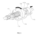
- FIG. 3 is a partial cross-sectional view of a fixing structure 100 shown in FIG. 2 .
- FIG. 4 is a perspective view of a fixing structure 100 according to another embodiment of the invention.
- FIG. 5 shows a C-shaped ring 120 among the components of the fixing structure 100 shown in FIG. 4 .
- FIG. 6 is a perspective view of a fixing structure 100 according to yet another embodiment of the invention.
- FIG. 7 is a perspective view of a fixing structure 100 according to still another embodiment of the invention.
- FIG. 8 is a perspective view of a wire fixing assistance member 141 among the components of the fixing structure 100 shown in FIG. 7 .
- connection encompasses a direct connection or an indirect connection (i.e., via separate components) between mechanical or other types of components.
- a connection between two rotating components may be a direct connection formed by the engagement of corresponding gear elements or the like, but may also be an indirect connection via a separate component such as a cable or a groove.
- FIG. 1 shows the overall appearance of a minimally invasive surgical instrument according to one embodiment of the invention.
- the minimally invasive surgical instrument may comprise a fixing structure (i.e. joint fixing structure) 100 ; a shaft 200 being connected to the fixing structure 100 ; a handling unit 300 that may be manipulated by a user; a first joint unit 400 being connected and disposed between the fixing structure 100 and the handling unit 300 to cause joint motion or the like of an end effector 600 (to be described below) according to the user's manipulation of the handling unit 300 ; a second joint unit 500 to allow the end effector 600 to carry out joint motion or the like in cooperation with the first joint unit 400 ; and the end effector 600 being connected to one end of the shaft 200 via the second joint unit 500 to perform surgery by using surgical tools (not shown) or functioning itself as a surgical tool.
- a fixing structure i.e. joint fixing structure
- a shaft 200 being connected to the fixing structure 100
- a handling unit 300 that may be manipulated by a user
- a first joint unit 400 being connected and disposed between the fixing structure 100 and the handling unit 300 to cause joint motion or the like of an
- the shaft 200 may include a cavity therein to support and pass at least one wire (not shown) or torque transmission member (not shown), in the same manner as those of the minimally invasive surgical instruments disclosed in the aforementioned Korean patent applications of the applicant(s).
- the torque transmission member is mainly intended for rolling motion of the end effector 600 , while the shaft 200 may function itself as the torque transmission member in some cases.
- the shaft 200 may comprise at least one segment as necessary. Further, the shaft 200 may comprise a bend in at least a part thereof.
- the handling unit 300 may control joint motion, rolling motion, opening/closing motion and the like of the end effector 600 according to the user's manipulation, in the same manner as those of the minimally invasive surgical instruments disclosed in the aforementioned Korean patent applications of the applicant(s).
- the at least one wire or torque transmission member may be connected to the handling unit 300 .
- first and second joint units 400 and 500 may act together with the at least one wire or torque transmission member to allow the end effector 600 to carry out joint motion, rolling motion and the like, in the same manner as those of the minimally invasive surgical instruments disclosed in the aforementioned Korean patent applications of the applicant(s).
- the end effector 600 may carry out joint motion, rolling motion, opening/closing motion and the like by the action of the at least one wire or torque transmission member passing from the handling unit 300 to the second joint unit 500 via the first joint unit 400 and the shaft 200 , in the same manner as those of the minimally invasive surgical instruments disclosed in the aforementioned Korean patent applications of the applicant(s).
- the tip of the end effector 600 may be implemented in the form of a clamp, a grasper, a pair of scissors, a stapler, a needle holder, a hook-type electrode or the like.
- the fixing structure 100 may hold a wire for controlling joint motion or the like of the end effector 600 so that the state of the joint motion of the end effector 600 may be firmly fixed.
- FIG. 2 is a partial cross-sectional view of the minimally invasive surgical instrument shown in FIG. 1 .
- the fixing structure 100 will be discussed below with further reference to FIG. 2 .
- the fixing structure 100 may comprise a spring 110 (preferably in the form of a coil). Further, the fixing structure 100 may comprise a wire guide path (e.g. a groove or pipe) extending from the handling unit 300 via the first joint unit 400 , or may further comprise a wire fixing assistance member 111 that may support the wire and assist it to be fixed. (In connection with one exemplary shape of the wire fixing assistance member 111 , reference may be made to FIG. 3 .) The spring 110 may surround the outer surface of the wire fixing assistance member 111 .
- One end of the spring 110 may be connected to a rotational motion member 112 . Further, the other end of the spring 110 may be fixed to a case 114 or the like to be described below. Accordingly, a part of the spring 110 is rotated when the rotational motion member 112 carries out rotational motion, so that the spring 100 may be twisted on the whole.
- the rotational motion member 112 may contact a linear motion member 113 .
- the above components may be disposed within the case 114 , which surrounds and covers them.
- FIG. 3 is a partial cross-sectional view of the fixing structure 100 shown in FIG. 2 . Further reference will be made to FIG. 3 .
- the rotational motion member 112 may comprise a slope 112 a at the portion contacting the linear motion member 113 , and the linear motion member 113 may also comprise a slope 113 a at the corresponding portion.
- the rotational motion member 112 may rotate so that the spring 110 may be rotated and twisted.
- the slope directions of the two slopes 112 a and 113 a may be determined such that the spring 110 is rotated and twisted according to the rotation of the rotational motion member 112 .
- the slope directions of the slopes 112 a and 113 a are determined as illustrated because the spring 110 is rotated and twisted when the rotational motion member 112 rotates counterclockwise (as seen from the linear motion member 113 ).
- the spring 110 When the spring 110 is rotated and twisted by the action of the linear motion member 113 and the rotational motion member 112 , an internal space of the portion where the spring 110 surrounds the outer surface of the wire fixing assistance member 111 may be reduced.
- the spring 110 may accordingly tighten the wire fixing assistance member 111 and further the wire guided or supported by the wire fixing assistance member 111 , so that the wire may be fixed.
- FIG. 4 is a perspective view of a fixing structure 100 according to another embodiment of the invention.
- FIG. 5 shows a C-shaped ring 120 among the components of the fixing structure 100 shown in FIG. 4 .
- the C-shaped ring 120 is employed instead of the spring 110 so that an internal space of the portion where it surrounds a wire fixing assistance member 121 may be reduced, thereby fixing the wire.
- the C-shaped ring 120 may surround the wire fixing assistance member 121 .
- the C-shaped ring 120 may comprise protrusions 120 a at both ends thereof, and the protrusions 120 a may be disposed in a groove 123 a formed in a linear motion member 123 .
- the groove 123 a may be formed (preferably in the form of a wedge or similar shape) such that an interval between the protrusions 120 a is reduced by the action of the linear motion member 123 (e.g., when the linear motion member 123 carries out linear motion toward the shaft 200 ) to allow the C-shaped ring 120 to tighten the wire fixing assistance member 121 .
- the present embodiment may also fix the wire as in the above-described embodiment.
- the portions of the C-shaped ring 120 and the wire fixing member 121 except the protrusions 120 a may be covered by covers 122 a and 122 b , and one end of the wire fixing assistance member 121 (represented as a cuboid-like shape in FIG. 4 ) may allow the wire fixing assistance member 121 to be fixed to the covers 122 a and 122 b to a certain degree.
- FIG. 6 is a perspective view of a fixing structure 100 according to yet another embodiment of the invention.
- a spring 130 is employed wherein a linear motion member 132 acts on both ends thereof so that an internal space of the portion where the spring 130 surrounds the outer surface of a wire fixing assistance member 131 may be reduced, thereby fixing the wire.
- the spring 130 may surround the outer surface of the wire fixing assistance member 131 .
- Protrusions 130 a may be formed at both ends of the spring 130 .
- the linear motion member 132 may comprise a front groove 133 and a rear groove 134 to allow the linear motion member 132 to act on the protrusions 130 a of the spring 130 when it carries out linear motion toward the shaft 120 , so that the spring 130 may tighten the wire fixing assistance member 131 .
- the protrusions 130 a may be inserted in the front and rear grooves 133 and 134 .
- the front and rear grooves 133 and 134 may be formed to be inclined with respect to the direction in which the linear motion member 132 carries out linear motion toward the shaft 200 , and to have the opposite inclinations. Therefore, the present embodiment may also fix the wire as in the above-described embodiments.
- FIG. 7 is a perspective view of a fixing structure 100 according to still another embodiment of the invention.
- FIG. 8 is a perspective view of a wire fixing assistance member 141 among the components of the fixing structure 100 shown in FIG. 7 .
- a spring 140 is employed wherein the spring 140 is twisted by means of two rotational motion members 143 and 144 , which are connected to both ends of the spring 140 , by the action of a linear motion member 142 so that an internal space of the portion where the spring 140 surrounds the outer surface of the wire fixing assistance member 141 may be reduced, thereby fixing the wire.
- the spring 140 may surround the outer surface of the wire fixing assistance member 141 . Both ends of the spring 140 may be connected to the first and second rotational motion members 143 and 144 , respectively. Therefore, when the first and second rotational motion members 143 and 144 rotate in the opposite directions, the spring 140 may accordingly be twisted. Meanwhile, the first and second rotational motion members 143 and 144 may comprise protrusions 143 a and 144 a , respectively.
- the linear motion member 142 may be further provided.
- the linear motion member 142 may comprise a first slope 142 a and a second slope 142 b .
- the first and second slopes 142 a and 142 b may be respectively inclined in a direction to enable the first and second rotational motion members 143 and 144 to carry out the rotational motion as above.
- the protrusions 143 a and 144 a may also comprise slopes.
- the present embodiment may also fix the wire as in the above-described embodiments.
- the wire fixing assistance member 141 may comprise a spring fixing unit 141 a , which may prevent the spring 140 from unnecessarily moving toward the shaft 200 or in the opposite direction or the like.
- a component such as the spring fixing unit 141 a may also be used in the above other embodiments employing a spring.
- those skilled in the art may partially change the form and such of the handling unit or the like so that the wire or torque transmission member of the minimally invasive surgical instrument may be operated or fixed by an electric motor or the like of another motor-based system (not shown) such as a surgical robot, as necessary.
Landscapes
- Health & Medical Sciences (AREA)
- Life Sciences & Earth Sciences (AREA)
- Surgery (AREA)
- Animal Behavior & Ethology (AREA)
- General Health & Medical Sciences (AREA)
- Engineering & Computer Science (AREA)
- Biomedical Technology (AREA)
- Heart & Thoracic Surgery (AREA)
- Veterinary Medicine (AREA)
- Public Health (AREA)
- Medical Informatics (AREA)
- Molecular Biology (AREA)
- Nuclear Medicine, Radiotherapy & Molecular Imaging (AREA)
- Ophthalmology & Optometry (AREA)
- Biophysics (AREA)
- Pulmonology (AREA)
- Anesthesiology (AREA)
- Hematology (AREA)
- Pathology (AREA)
- Manipulator (AREA)
- Surgical Instruments (AREA)
Abstract
The present invention relates to a minimally invasive surgical instrument having an articulation immobilizing structure. The present invention is a minimally invasive surgical instrument and includes a shaft, an end effector connected towards one end of the shaft, a wire for controlling the articulated movement of the end effector, and an immobilizing structure adapted to immobilize the state of articulated movement of the end effector. The immobilizing structure includes a resilient member covering the wire, and the resilient member holds the wire when an internal space therein contracts.
Description
The present invention relates to a minimally invasive surgical instrument having a joint fixing structure.
Minimally invasive surgery is a surgical approach that involves the use of instruments inserted through at least one tiny incision opening to perform a surgery causing minimal tissue trauma in human or animal bodies.
The minimally invasive surgery relatively reduces changes in metabolism of a patient in the period of post-surgical care, so it facilitates rapid recovery of the patient. Therefore, the minimally invasive surgery shortens the length of hospitalization of the patient after the surgery and allows the patient to return to normal physical activities in a short period of time. In addition, the minimally invasive surgery causes less pain and leaves fewer scars on the patient's body after the surgery.
One of the general forms of the minimally invasive surgery is endoscopy. Among the others, a laparoscopy that involves minimally invasive inspection and operation inside abdominal cavity is known as the most general form of endoscopy. To operate a standard laparoscopic surgery, the abdomen of the patient is insufflated with gas and at least one small incision is formed to provide an entrance for laparoscopic surgical instruments, through which a trocar is inserted. When performing the surgery, it is general that a user puts the laparoscopic surgical instruments into a surgical site or the like through the trocar, and manipulates (or controls) the instruments from the outside of abdominal cavity. In general, the laparoscopic surgical instruments include a laparoscope (for observation of a surgical site) and other working tools. Herein, the working tools are similar to the conventional tools used for small incision surgery, except that the end effector or working end of each tool is separated from its handle or the like by a shaft. For instance, the working tools may include a clamp, a grasper, scissors, a stapler, a needle holder, and so forth. Meanwhile, the user monitors the procedure of the surgery through a monitor that displays the images of the surgical site which are taken by the laparoscope. The endoscopic approaches similar to the above are broadly used in retroperitoneoscopy, pelviscopy, arthroscopy, cisternoscopy, sinuscopy, hysteroscopy, nephroscopy, cystoscopy, urethroscopy, pyeloscopy, and so on.
The inventor(s) has developed various minimally invasive surgical instruments useful for the above-mentioned minimally invasive surgeries and has already disclosed the features of the structures and effects of the same in Korean Patent Application Nos. 2008-51248, 2008-61894, 2008-79126 and 2008-90560, the contents of which are to be regarded as being incorporated herein by reference in its entirety. Additionally, the inventor(s) have also introduced a minimally invasive surgical instrument with improved functionality, which is more advantageous for users and patients, in Korean Patent Application Nos. 2010-115152, 2011-3192, 2011-26243, 2011-29771, 2011-86738, 2011-89854 and the like, the contents of which are to be regarded as being incorporated herein by reference in its entirety.
Herein, the inventor(s) now present a joint fixing structure having excellent capabilities, which may be widely employed in the minimally invasive surgical instruments disclosed in the aforementioned Korean patent applications or other minimally invasive surgical instruments.
One object of the present invention is to provide a minimally invasive surgical instrument having a joint fixing structure to hold a wire for controlling joint motion of an end effector so that the state of the joint motion thereof may be firmly fixed.
According to one aspect of the invention to achieve the object as described above, there is provided a minimally invasive surgical instrument comprising a shaft; an end effector being connected to one end of the shaft; a wire to control joint motion of the end effector; and a fixing structure to fix the state of the joint motion of the end effector, wherein the fixing structure comprises an elastic member surrounding the wire, and the elastic member holds the wire as an internal space thereof is reduced.
According to the invention, there is provided a minimally invasive surgical instrument having a joint fixing structure to hold a wire for controlling joint motion of an end effector so that the state of the joint motion thereof may be firmly fixed.
In the following detailed description of the present invention, references are made to the accompanying drawings that show, by way of illustration, specific embodiments in which the invention may be practiced. These embodiments are described in sufficient detail to enable those skilled in the art to practice the invention. It is to be understood that the various embodiments of the invention, although different from each other, are not necessarily mutually exclusive. For example, specific shapes, structures and characteristics described herein may be implemented as modified from one embodiment to another without departing from the spirit and scope of the invention. Furthermore, it shall be understood that the locations or arrangements of individual components within each embodiment may also be modified without departing from the spirit and scope of the invention. Therefore, the following detailed description is not to be taken in a limiting sense, and the scope of the invention is to be taken as encompassing the scope of the appended claims and all equivalents thereof. In the drawings, like reference numerals refer to the same or similar elements throughout the several views.
Hereinafter, preferred embodiments of the present invention will be described in detail with reference to the accompanying drawings to enable those skilled in the art to easily implement the invention.
Meanwhile, it should be understood that the term “connection” herein encompasses a direct connection or an indirect connection (i.e., via separate components) between mechanical or other types of components. For example, a connection between two rotating components may be a direct connection formed by the engagement of corresponding gear elements or the like, but may also be an indirect connection via a separate component such as a cable or a groove.
Reference will be made to FIG. 1 . The minimally invasive surgical instrument may comprise a fixing structure (i.e. joint fixing structure) 100; a shaft 200 being connected to the fixing structure 100; a handling unit 300 that may be manipulated by a user; a first joint unit 400 being connected and disposed between the fixing structure 100 and the handling unit 300 to cause joint motion or the like of an end effector 600 (to be described below) according to the user's manipulation of the handling unit 300; a second joint unit 500 to allow the end effector 600 to carry out joint motion or the like in cooperation with the first joint unit 400; and the end effector 600 being connected to one end of the shaft 200 via the second joint unit 500 to perform surgery by using surgical tools (not shown) or functioning itself as a surgical tool.
First, the shaft 200 may include a cavity therein to support and pass at least one wire (not shown) or torque transmission member (not shown), in the same manner as those of the minimally invasive surgical instruments disclosed in the aforementioned Korean patent applications of the applicant(s). (The torque transmission member is mainly intended for rolling motion of the end effector 600, while the shaft 200 may function itself as the torque transmission member in some cases.) The shaft 200 may comprise at least one segment as necessary. Further, the shaft 200 may comprise a bend in at least a part thereof.
Next, the handling unit 300 may control joint motion, rolling motion, opening/closing motion and the like of the end effector 600 according to the user's manipulation, in the same manner as those of the minimally invasive surgical instruments disclosed in the aforementioned Korean patent applications of the applicant(s). To allow for such control, the at least one wire or torque transmission member may be connected to the handling unit 300.
Next, the first and second joint units 400 and 500 may act together with the at least one wire or torque transmission member to allow the end effector 600 to carry out joint motion, rolling motion and the like, in the same manner as those of the minimally invasive surgical instruments disclosed in the aforementioned Korean patent applications of the applicant(s).
Next, the end effector 600 may carry out joint motion, rolling motion, opening/closing motion and the like by the action of the at least one wire or torque transmission member passing from the handling unit 300 to the second joint unit 500 via the first joint unit 400 and the shaft 200, in the same manner as those of the minimally invasive surgical instruments disclosed in the aforementioned Korean patent applications of the applicant(s). The tip of the end effector 600 may be implemented in the form of a clamp, a grasper, a pair of scissors, a stapler, a needle holder, a hook-type electrode or the like.
Finally, the fixing structure 100 may hold a wire for controlling joint motion or the like of the end effector 600 so that the state of the joint motion of the end effector 600 may be firmly fixed.
The fixing structure 100 may comprise a spring 110 (preferably in the form of a coil). Further, the fixing structure 100 may comprise a wire guide path (e.g. a groove or pipe) extending from the handling unit 300 via the first joint unit 400, or may further comprise a wire fixing assistance member 111 that may support the wire and assist it to be fixed. (In connection with one exemplary shape of the wire fixing assistance member 111, reference may be made to FIG. 3 .) The spring 110 may surround the outer surface of the wire fixing assistance member 111.
One end of the spring 110 may be connected to a rotational motion member 112. Further, the other end of the spring 110 may be fixed to a case 114 or the like to be described below. Accordingly, a part of the spring 110 is rotated when the rotational motion member 112 carries out rotational motion, so that the spring 100 may be twisted on the whole. The rotational motion member 112 may contact a linear motion member 113. The above components may be disposed within the case 114, which surrounds and covers them.
The rotational motion member 112 may comprise a slope 112 a at the portion contacting the linear motion member 113, and the linear motion member 113 may also comprise a slope 113 a at the corresponding portion. Thus, when the slope 113 a applies a force to the slope 112 a by the action of the linear motion member 113 (e.g., the action in which the linear motion member 113 carries out linear motion toward the rotational motion member 112 according to the manipulation of the handling unit 300 and then the state of the motion thereof is fixed), the rotational motion member 112 may rotate so that the spring 110 may be rotated and twisted. The slope directions of the two slopes 112 a and 113 a may be determined such that the spring 110 is rotated and twisted according to the rotation of the rotational motion member 112. In case of FIG. 3 , the slope directions of the slopes 112 a and 113 a are determined as illustrated because the spring 110 is rotated and twisted when the rotational motion member 112 rotates counterclockwise (as seen from the linear motion member 113).
When the spring 110 is rotated and twisted by the action of the linear motion member 113 and the rotational motion member 112, an internal space of the portion where the spring 110 surrounds the outer surface of the wire fixing assistance member 111 may be reduced. The spring 110 may accordingly tighten the wire fixing assistance member 111 and further the wire guided or supported by the wire fixing assistance member 111, so that the wire may be fixed.
The C-shaped ring 120 according the present embodiment (preferably a plurality of the C-shaped rings 120) may surround the wire fixing assistance member 121. The C-shaped ring 120 may comprise protrusions 120 a at both ends thereof, and the protrusions 120 a may be disposed in a groove 123 a formed in a linear motion member 123. As illustrated, the groove 123 a may be formed (preferably in the form of a wedge or similar shape) such that an interval between the protrusions 120 a is reduced by the action of the linear motion member 123 (e.g., when the linear motion member 123 carries out linear motion toward the shaft 200) to allow the C-shaped ring 120 to tighten the wire fixing assistance member 121. Therefore, the present embodiment may also fix the wire as in the above-described embodiment. Meanwhile, the portions of the C-shaped ring 120 and the wire fixing member 121 except the protrusions 120 a may be covered by covers 122 a and 122 b, and one end of the wire fixing assistance member 121 (represented as a cuboid-like shape in FIG. 4 ) may allow the wire fixing assistance member 121 to be fixed to the covers 122 a and 122 b to a certain degree.
The spring 130 according to the present embodiment may surround the outer surface of the wire fixing assistance member 131. Protrusions 130 a may be formed at both ends of the spring 130. Meanwhile, the linear motion member 132 may comprise a front groove 133 and a rear groove 134 to allow the linear motion member 132 to act on the protrusions 130 a of the spring 130 when it carries out linear motion toward the shaft 120, so that the spring 130 may tighten the wire fixing assistance member 131. (The protrusions 130 a may be inserted in the front and rear grooves 133 and 134.) As illustrated, the front and rear grooves 133 and 134 may be formed to be inclined with respect to the direction in which the linear motion member 132 carries out linear motion toward the shaft 200, and to have the opposite inclinations. Therefore, the present embodiment may also fix the wire as in the above-described embodiments.
The spring 140 according to the present embodiment may surround the outer surface of the wire fixing assistance member 141. Both ends of the spring 140 may be connected to the first and second rotational motion members 143 and 144, respectively. Therefore, when the first and second rotational motion members 143 and 144 rotate in the opposite directions, the spring 140 may accordingly be twisted. Meanwhile, the first and second rotational motion members 143 and 144 may comprise protrusions 143 a and 144 a, respectively.
Further, the linear motion member 142 may be further provided. The linear motion member 142 may comprise a first slope 142 a and a second slope 142 b. The first and second slopes 142 a and 142 b may be respectively inclined in a direction to enable the first and second rotational motion members 143 and 144 to carry out the rotational motion as above. (Correspondingly, the protrusions 143 a and 144 a may also comprise slopes.)
Accordingly, when the linear motion member 142 carries out linear motion toward the shaft 200, for example, the first slope 142 a applies a force to the protrusion 143 a to allow the first rotational motion member 143 to rotate clockwise (as seen from the handling unit 300), and the second slope 142 b applies a force to the protrusion 144 a to allow the second rotational motion member 144 to rotate counterclockwise. Therefore, the present embodiment may also fix the wire as in the above-described embodiments. Meanwhile, as illustrated in FIG. 8 , the wire fixing assistance member 141 may comprise a spring fixing unit 141 a, which may prevent the spring 140 from unnecessarily moving toward the shaft 200 or in the opposite direction or the like. A component such as the spring fixing unit 141 a may also be used in the above other embodiments employing a spring.
According to an application of the present invention, those skilled in the art may partially change the form and such of the handling unit or the like so that the wire or torque transmission member of the minimally invasive surgical instrument may be operated or fixed by an electric motor or the like of another motor-based system (not shown) such as a surgical robot, as necessary.
Although the present invention has been described in terms of specific items such as detailed components as well as the limited embodiments and the drawings, they are only provided to help general understanding of the invention, and the present invention is not limited to the above embodiments. It will be appreciated by those skilled in the art that various modifications and changes may be made from the above description.
Therefore, the spirit of the present invention shall not be limited to the above-described embodiments, and the entire scope of the appended claims and their equivalents will fall within the scope and spirit of the invention.
Claims (4)
1. A minimally invasive surgical instrument, comprising:
a shaft;
an end effector being connected to one end of the shaft;
a wire to control articulating motion of the end effector; and
a fixing structure to fix a state of the articulating motion of the end effector,
wherein the fixing structure comprises an elastic member;
the fixing structure further comprises a wire fixing assistance member to guide or support the wire;
the fixing structure further comprises a rotational motion member, the rotational motion member being rotatable along an axis of the shaft;
the elastic member is a spring one end of which is connected to the rotational motion member;
the spring surrounds the wire and the wire fixing assistance member; and
an internal space of the spring is reduced as the rotational motion member rotates.
2. The minimally invasive surgical instrument as claimed in claim 1 , wherein the wire fixing assistance member comprises a wire guide path.
3. The minimally invasive surgical instrument as claimed in claim 1 , wherein the fixing structure further comprises a linear motion member, and the internal space of the elastic member is reduced as the linear motion member carries out linear motion.
4. The minimally invasive surgical instrument as claimed in claim 1 , wherein the wire fixing assistance member comprises a fixing unit to restrict the movement of the elastic member.
Applications Claiming Priority (3)
| Application Number | Priority Date | Filing Date | Title |
|---|---|---|---|
| KR10-2012-0034090 | 2012-04-02 | ||
| KR1020120034090A KR101365357B1 (en) | 2012-04-02 | 2012-04-02 | Instrument for Minimally Invasive Surgery Having Articulation Fixing Structure |
| PCT/KR2013/002472 WO2013151262A1 (en) | 2012-04-02 | 2013-03-26 | Minimally invasive surgical instrument having articulation immobilising structure |
Related Parent Applications (1)
| Application Number | Title | Priority Date | Filing Date |
|---|---|---|---|
| PCT/KR2013/002472 A-371-Of-International WO2013151262A1 (en) | 2012-04-02 | 2013-03-26 | Minimally invasive surgical instrument having articulation immobilising structure |
Related Child Applications (1)
| Application Number | Title | Priority Date | Filing Date |
|---|---|---|---|
| US16/231,661 Division US10966695B2 (en) | 2012-04-02 | 2018-12-24 | Minimally invasive surgical instrument having articulation immobilising structure |
Publications (2)
| Publication Number | Publication Date |
|---|---|
| US20150066001A1 US20150066001A1 (en) | 2015-03-05 |
| US10194891B2 true US10194891B2 (en) | 2019-02-05 |
Family
ID=49300709
Family Applications (2)
| Application Number | Title | Priority Date | Filing Date |
|---|---|---|---|
| US14/390,287 Active 2035-09-28 US10194891B2 (en) | 2012-04-02 | 2013-03-26 | Minimally invasive surgical instrument having articulation immobilising structure |
| US16/231,661 Active 2033-09-21 US10966695B2 (en) | 2012-04-02 | 2018-12-24 | Minimally invasive surgical instrument having articulation immobilising structure |
Family Applications After (1)
| Application Number | Title | Priority Date | Filing Date |
|---|---|---|---|
| US16/231,661 Active 2033-09-21 US10966695B2 (en) | 2012-04-02 | 2018-12-24 | Minimally invasive surgical instrument having articulation immobilising structure |
Country Status (6)
| Country | Link |
|---|---|
| US (2) | US10194891B2 (en) |
| EP (1) | EP2835107B1 (en) |
| JP (1) | JP2015513951A (en) |
| KR (1) | KR101365357B1 (en) |
| CN (1) | CN104093372A (en) |
| WO (1) | WO2013151262A1 (en) |
Cited By (115)
| Publication number | Priority date | Publication date | Assignee | Title |
|---|---|---|---|---|
| US11096693B2 (en) | 2017-12-28 | 2021-08-24 | Cilag Gmbh International | Adjustment of staple height of at least one row of staples based on the sensed tissue thickness or force in closing |
| US11114195B2 (en) | 2017-12-28 | 2021-09-07 | Cilag Gmbh International | Surgical instrument with a tissue marking assembly |
| US11129611B2 (en) | 2018-03-28 | 2021-09-28 | Cilag Gmbh International | Surgical staplers with arrangements for maintaining a firing member thereof in a locked configuration unless a compatible cartridge has been installed therein |
| US11132462B2 (en) | 2017-12-28 | 2021-09-28 | Cilag Gmbh International | Data stripping method to interrogate patient records and create anonymized record |
| US11129636B2 (en) | 2017-10-30 | 2021-09-28 | Cilag Gmbh International | Surgical instruments comprising an articulation drive that provides for high articulation angles |
| US11160605B2 (en) | 2017-12-28 | 2021-11-02 | Cilag Gmbh International | Surgical evacuation sensing and motor control |
| US11166772B2 (en) | 2017-12-28 | 2021-11-09 | Cilag Gmbh International | Surgical hub coordination of control and communication of operating room devices |
| US11179208B2 (en) | 2017-12-28 | 2021-11-23 | Cilag Gmbh International | Cloud-based medical analytics for security and authentication trends and reactive measures |
| US11179204B2 (en) | 2017-12-28 | 2021-11-23 | Cilag Gmbh International | Wireless pairing of a surgical device with another device within a sterile surgical field based on the usage and situational awareness of devices |
| US11202570B2 (en) | 2017-12-28 | 2021-12-21 | Cilag Gmbh International | Communication hub and storage device for storing parameters and status of a surgical device to be shared with cloud based analytics systems |
| US11207067B2 (en) | 2018-03-28 | 2021-12-28 | Cilag Gmbh International | Surgical stapling device with separate rotary driven closure and firing systems and firing member that engages both jaws while firing |
| US11213359B2 (en) | 2017-12-28 | 2022-01-04 | Cilag Gmbh International | Controllers for robot-assisted surgical platforms |
| US11219453B2 (en) | 2018-03-28 | 2022-01-11 | Cilag Gmbh International | Surgical stapling devices with cartridge compatible closure and firing lockout arrangements |
| US11229436B2 (en) | 2017-10-30 | 2022-01-25 | Cilag Gmbh International | Surgical system comprising a surgical tool and a surgical hub |
| US11234756B2 (en) | 2017-12-28 | 2022-02-01 | Cilag Gmbh International | Powered surgical tool with predefined adjustable control algorithm for controlling end effector parameter |
| US11253315B2 (en) | 2017-12-28 | 2022-02-22 | Cilag Gmbh International | Increasing radio frequency to create pad-less monopolar loop |
| US11257589B2 (en) | 2017-12-28 | 2022-02-22 | Cilag Gmbh International | Real-time analysis of comprehensive cost of all instrumentation used in surgery utilizing data fluidity to track instruments through stocking and in-house processes |
| US11259830B2 (en) | 2018-03-08 | 2022-03-01 | Cilag Gmbh International | Methods for controlling temperature in ultrasonic device |
| US11259806B2 (en) | 2018-03-28 | 2022-03-01 | Cilag Gmbh International | Surgical stapling devices with features for blocking advancement of a camming assembly of an incompatible cartridge installed therein |
| US11259807B2 (en) | 2019-02-19 | 2022-03-01 | Cilag Gmbh International | Staple cartridges with cam surfaces configured to engage primary and secondary portions of a lockout of a surgical stapling device |
| US11266468B2 (en) | 2017-12-28 | 2022-03-08 | Cilag Gmbh International | Cooperative utilization of data derived from secondary sources by intelligent surgical hubs |
| US11273001B2 (en) | 2017-12-28 | 2022-03-15 | Cilag Gmbh International | Surgical hub and modular device response adjustment based on situational awareness |
| US11278281B2 (en) | 2017-12-28 | 2022-03-22 | Cilag Gmbh International | Interactive surgical system |
| US11278280B2 (en) | 2018-03-28 | 2022-03-22 | Cilag Gmbh International | Surgical instrument comprising a jaw closure lockout |
| US11284936B2 (en) | 2017-12-28 | 2022-03-29 | Cilag Gmbh International | Surgical instrument having a flexible electrode |
| US11291495B2 (en) | 2017-12-28 | 2022-04-05 | Cilag Gmbh International | Interruption of energy due to inadvertent capacitive coupling |
| US11291510B2 (en) | 2017-10-30 | 2022-04-05 | Cilag Gmbh International | Method of hub communication with surgical instrument systems |
| US11298148B2 (en) | 2018-03-08 | 2022-04-12 | Cilag Gmbh International | Live time tissue classification using electrical parameters |
| US11304763B2 (en) | 2017-12-28 | 2022-04-19 | Cilag Gmbh International | Image capturing of the areas outside the abdomen to improve placement and control of a surgical device in use |
| US11308075B2 (en) | 2017-12-28 | 2022-04-19 | Cilag Gmbh International | Surgical network, instrument, and cloud responses based on validation of received dataset and authentication of its source and integrity |
| US11304699B2 (en) | 2017-12-28 | 2022-04-19 | Cilag Gmbh International | Method for adaptive control schemes for surgical network control and interaction |
| US11304720B2 (en) | 2017-12-28 | 2022-04-19 | Cilag Gmbh International | Activation of energy devices |
| US11304745B2 (en) | 2017-12-28 | 2022-04-19 | Cilag Gmbh International | Surgical evacuation sensing and display |
| US11311306B2 (en) | 2017-12-28 | 2022-04-26 | Cilag Gmbh International | Surgical systems for detecting end effector tissue distribution irregularities |
| US11311342B2 (en) | 2017-10-30 | 2022-04-26 | Cilag Gmbh International | Method for communicating with surgical instrument systems |
| US11317915B2 (en) | 2019-02-19 | 2022-05-03 | Cilag Gmbh International | Universal cartridge based key feature that unlocks multiple lockout arrangements in different surgical staplers |
| USD950728S1 (en) | 2019-06-25 | 2022-05-03 | Cilag Gmbh International | Surgical staple cartridge |
| US11317919B2 (en) | 2017-10-30 | 2022-05-03 | Cilag Gmbh International | Clip applier comprising a clip crimping system |
| US11317937B2 (en) | 2018-03-08 | 2022-05-03 | Cilag Gmbh International | Determining the state of an ultrasonic end effector |
| US11324557B2 (en) | 2017-12-28 | 2022-05-10 | Cilag Gmbh International | Surgical instrument with a sensing array |
| USD952144S1 (en) | 2019-06-25 | 2022-05-17 | Cilag Gmbh International | Surgical staple cartridge retainer with firing system authentication key |
| US11337746B2 (en) | 2018-03-08 | 2022-05-24 | Cilag Gmbh International | Smart blade and power pulsing |
| US11357503B2 (en) | 2019-02-19 | 2022-06-14 | Cilag Gmbh International | Staple cartridge retainers with frangible retention features and methods of using same |
| US11364075B2 (en) | 2017-12-28 | 2022-06-21 | Cilag Gmbh International | Radio frequency energy device for delivering combined electrical signals |
| US11369377B2 (en) | 2019-02-19 | 2022-06-28 | Cilag Gmbh International | Surgical stapling assembly with cartridge based retainer configured to unlock a firing lockout |
| US11376002B2 (en) | 2017-12-28 | 2022-07-05 | Cilag Gmbh International | Surgical instrument cartridge sensor assemblies |
| US11382697B2 (en) | 2017-12-28 | 2022-07-12 | Cilag Gmbh International | Surgical instruments comprising button circuits |
| US11389164B2 (en) | 2017-12-28 | 2022-07-19 | Cilag Gmbh International | Method of using reinforced flexible circuits with multiple sensors to optimize performance of radio frequency devices |
| US11406390B2 (en) | 2017-10-30 | 2022-08-09 | Cilag Gmbh International | Clip applier comprising interchangeable clip reloads |
| US11410259B2 (en) | 2017-12-28 | 2022-08-09 | Cilag Gmbh International | Adaptive control program updates for surgical devices |
| US11424027B2 (en) | 2017-12-28 | 2022-08-23 | Cilag Gmbh International | Method for operating surgical instrument systems |
| US11423007B2 (en) | 2017-12-28 | 2022-08-23 | Cilag Gmbh International | Adjustment of device control programs based on stratified contextual data in addition to the data |
| US11419630B2 (en) | 2017-12-28 | 2022-08-23 | Cilag Gmbh International | Surgical system distributed processing |
| US11419667B2 (en) | 2017-12-28 | 2022-08-23 | Cilag Gmbh International | Ultrasonic energy device which varies pressure applied by clamp arm to provide threshold control pressure at a cut progression location |
| US11432885B2 (en) | 2017-12-28 | 2022-09-06 | Cilag Gmbh International | Sensing arrangements for robot-assisted surgical platforms |
| US11446052B2 (en) | 2017-12-28 | 2022-09-20 | Cilag Gmbh International | Variation of radio frequency and ultrasonic power level in cooperation with varying clamp arm pressure to achieve predefined heat flux or power applied to tissue |
| USD964564S1 (en) | 2019-06-25 | 2022-09-20 | Cilag Gmbh International | Surgical staple cartridge retainer with a closure system authentication key |
| US11464535B2 (en) | 2017-12-28 | 2022-10-11 | Cilag Gmbh International | Detection of end effector emersion in liquid |
| US11464511B2 (en) | 2019-02-19 | 2022-10-11 | Cilag Gmbh International | Surgical staple cartridges with movable authentication key arrangements |
| US11464559B2 (en) | 2017-12-28 | 2022-10-11 | Cilag Gmbh International | Estimating state of ultrasonic end effector and control system therefor |
| US11471156B2 (en) | 2018-03-28 | 2022-10-18 | Cilag Gmbh International | Surgical stapling devices with improved rotary driven closure systems |
| US11504192B2 (en) | 2014-10-30 | 2022-11-22 | Cilag Gmbh International | Method of hub communication with surgical instrument systems |
| US11510741B2 (en) | 2017-10-30 | 2022-11-29 | Cilag Gmbh International | Method for producing a surgical instrument comprising a smart electrical system |
| US11529187B2 (en) | 2017-12-28 | 2022-12-20 | Cilag Gmbh International | Surgical evacuation sensor arrangements |
| US11540855B2 (en) | 2017-12-28 | 2023-01-03 | Cilag Gmbh International | Controlling activation of an ultrasonic surgical instrument according to the presence of tissue |
| US11559307B2 (en) | 2017-12-28 | 2023-01-24 | Cilag Gmbh International | Method of robotic hub communication, detection, and control |
| US11559308B2 (en) | 2017-12-28 | 2023-01-24 | Cilag Gmbh International | Method for smart energy device infrastructure |
| US11564756B2 (en) | 2017-10-30 | 2023-01-31 | Cilag Gmbh International | Method of hub communication with surgical instrument systems |
| US11571234B2 (en) | 2017-12-28 | 2023-02-07 | Cilag Gmbh International | Temperature control of ultrasonic end effector and control system therefor |
| US11576677B2 (en) | 2017-12-28 | 2023-02-14 | Cilag Gmbh International | Method of hub communication, processing, display, and cloud analytics |
| US11589888B2 (en) | 2017-12-28 | 2023-02-28 | Cilag Gmbh International | Method for controlling smart energy devices |
| US11589932B2 (en) | 2017-12-28 | 2023-02-28 | Cilag Gmbh International | Usage and technique analysis of surgeon / staff performance against a baseline to optimize device utilization and performance for both current and future procedures |
| US11596291B2 (en) | 2017-12-28 | 2023-03-07 | Cilag Gmbh International | Method of compressing tissue within a stapling device and simultaneously displaying of the location of the tissue within the jaws |
| US11601371B2 (en) | 2017-12-28 | 2023-03-07 | Cilag Gmbh International | Surgical network determination of prioritization of communication, interaction, or processing based on system or device needs |
| US11602393B2 (en) | 2017-12-28 | 2023-03-14 | Cilag Gmbh International | Surgical evacuation sensing and generator control |
| US11612444B2 (en) | 2017-12-28 | 2023-03-28 | Cilag Gmbh International | Adjustment of a surgical device function based on situational awareness |
| US11612408B2 (en) | 2017-12-28 | 2023-03-28 | Cilag Gmbh International | Determining tissue composition via an ultrasonic system |
| US11659023B2 (en) | 2017-12-28 | 2023-05-23 | Cilag Gmbh International | Method of hub communication |
| US11666331B2 (en) | 2017-12-28 | 2023-06-06 | Cilag Gmbh International | Systems for detecting proximity of surgical end effector to cancerous tissue |
| US11696760B2 (en) | 2017-12-28 | 2023-07-11 | Cilag Gmbh International | Safety systems for smart powered surgical stapling |
| US11744604B2 (en) | 2017-12-28 | 2023-09-05 | Cilag Gmbh International | Surgical instrument with a hardware-only control circuit |
| US11771487B2 (en) | 2017-12-28 | 2023-10-03 | Cilag Gmbh International | Mechanisms for controlling different electromechanical systems of an electrosurgical instrument |
| US11786251B2 (en) | 2017-12-28 | 2023-10-17 | Cilag Gmbh International | Method for adaptive control schemes for surgical network control and interaction |
| US11786245B2 (en) | 2017-12-28 | 2023-10-17 | Cilag Gmbh International | Surgical systems with prioritized data transmission capabilities |
| US11801098B2 (en) | 2017-10-30 | 2023-10-31 | Cilag Gmbh International | Method of hub communication with surgical instrument systems |
| US11818052B2 (en) | 2017-12-28 | 2023-11-14 | Cilag Gmbh International | Surgical network determination of prioritization of communication, interaction, or processing based on system or device needs |
| US11832840B2 (en) | 2017-12-28 | 2023-12-05 | Cilag Gmbh International | Surgical instrument having a flexible circuit |
| US11832899B2 (en) | 2017-12-28 | 2023-12-05 | Cilag Gmbh International | Surgical systems with autonomously adjustable control programs |
| US11857152B2 (en) | 2017-12-28 | 2024-01-02 | Cilag Gmbh International | Surgical hub spatial awareness to determine devices in operating theater |
| US11864728B2 (en) | 2017-12-28 | 2024-01-09 | Cilag Gmbh International | Characterization of tissue irregularities through the use of mono-chromatic light refractivity |
| US11871901B2 (en) | 2012-05-20 | 2024-01-16 | Cilag Gmbh International | Method for situational awareness for surgical network or surgical network connected device capable of adjusting function based on a sensed situation or usage |
| US11890065B2 (en) | 2017-12-28 | 2024-02-06 | Cilag Gmbh International | Surgical system to limit displacement |
| US11896443B2 (en) | 2017-12-28 | 2024-02-13 | Cilag Gmbh International | Control of a surgical system through a surgical barrier |
| US11896322B2 (en) | 2017-12-28 | 2024-02-13 | Cilag Gmbh International | Sensing the patient position and contact utilizing the mono-polar return pad electrode to provide situational awareness to the hub |
| US11903601B2 (en) | 2017-12-28 | 2024-02-20 | Cilag Gmbh International | Surgical instrument comprising a plurality of drive systems |
| US11903587B2 (en) | 2017-12-28 | 2024-02-20 | Cilag Gmbh International | Adjustment to the surgical stapling control based on situational awareness |
| US11911045B2 (en) | 2017-10-30 | 2024-02-27 | Cllag GmbH International | Method for operating a powered articulating multi-clip applier |
| US11931027B2 (en) | 2018-03-28 | 2024-03-19 | Cilag Gmbh Interntional | Surgical instrument comprising an adaptive control system |
| US11937769B2 (en) | 2017-12-28 | 2024-03-26 | Cilag Gmbh International | Method of hub communication, processing, storage and display |
| US11969216B2 (en) | 2017-12-28 | 2024-04-30 | Cilag Gmbh International | Surgical network recommendations from real time analysis of procedure variables against a baseline highlighting differences from the optimal solution |
| US11998193B2 (en) | 2017-12-28 | 2024-06-04 | Cilag Gmbh International | Method for usage of the shroud as an aspect of sensing or controlling a powered surgical device, and a control algorithm to adjust its default operation |
| US12029506B2 (en) | 2017-12-28 | 2024-07-09 | Cilag Gmbh International | Method of cloud based data analytics for use with the hub |
| US12035890B2 (en) | 2017-12-28 | 2024-07-16 | Cilag Gmbh International | Method of sensing particulate from smoke evacuated from a patient, adjusting the pump speed based on the sensed information, and communicating the functional parameters of the system to the hub |
| US12048496B2 (en) | 2017-12-28 | 2024-07-30 | Cilag Gmbh International | Adaptive control program updates for surgical hubs |
| US12062442B2 (en) | 2017-12-28 | 2024-08-13 | Cilag Gmbh International | Method for operating surgical instrument systems |
| US12127729B2 (en) | 2017-12-28 | 2024-10-29 | Cilag Gmbh International | Method for smoke evacuation for surgical hub |
| US12133773B2 (en) | 2017-12-28 | 2024-11-05 | Cilag Gmbh International | Surgical hub and modular device response adjustment based on situational awareness |
| US12226151B2 (en) | 2017-12-28 | 2025-02-18 | Cilag Gmbh International | Capacitive coupled return path pad with separable array elements |
| US12303159B2 (en) | 2018-03-08 | 2025-05-20 | Cilag Gmbh International | Methods for estimating and controlling state of ultrasonic end effector |
| US12318152B2 (en) | 2017-12-28 | 2025-06-03 | Cilag Gmbh International | Computer implemented interactive surgical systems |
| US12376855B2 (en) | 2017-12-28 | 2025-08-05 | Cilag Gmbh International | Safety systems for smart powered surgical stapling |
| US12396806B2 (en) | 2017-12-28 | 2025-08-26 | Cilag Gmbh International | Adjustment of a surgical device function based on situational awareness |
| US12433508B2 (en) | 2017-12-28 | 2025-10-07 | Cilag Gmbh International | Surgical system having a surgical instrument controlled based on comparison of sensor and database data |
| US12458351B2 (en) | 2017-12-28 | 2025-11-04 | Cilag Gmbh International | Variable output cartridge sensor assembly |
| US12521191B2 (en) | 2017-12-28 | 2026-01-13 | Cilag Gmbh International | Adjustment of a surgical device function based on situational awareness |
Families Citing this family (2)
| Publication number | Priority date | Publication date | Assignee | Title |
|---|---|---|---|---|
| DE102013005982A1 (en) * | 2013-04-08 | 2014-10-09 | Kuka Laboratories Gmbh | medical robots |
| KR102629040B1 (en) * | 2021-11-03 | 2024-01-23 | 이화여자대학교 산학협력단 | Driving Apparatus For Wire-Based Steerable Needle |
Citations (9)
| Publication number | Priority date | Publication date | Assignee | Title |
|---|---|---|---|---|
| US20050096694A1 (en) * | 2003-10-30 | 2005-05-05 | Woojin Lee | Surgical instrument |
| US20050182298A1 (en) * | 2002-12-06 | 2005-08-18 | Intuitive Surgical Inc. | Cardiac tissue ablation instrument with flexible wrist |
| JP2008049104A (en) | 2006-08-28 | 2008-03-06 | River Seiko:Kk | Endoscopic treatment tool |
| US20090108048A1 (en) * | 2007-10-31 | 2009-04-30 | Tyco Healthcare Group Lp | Powered surgical instrument |
| JP2010136831A (en) | 2008-12-10 | 2010-06-24 | Fujifilm Corp | Repeating type clip treatment instrument |
| US20100191278A1 (en) * | 2003-10-30 | 2010-07-29 | Cambridge Endoscopic Devices, Inc. | Surgical instrument |
| JP2010207340A (en) | 2009-03-09 | 2010-09-24 | Hoya Corp | Endoscope guiding tube device |
| KR101075294B1 (en) | 2011-01-12 | 2011-10-19 | 정창욱 | Minimally invasive surgical instruments |
| US20120059408A1 (en) * | 2010-09-07 | 2012-03-08 | Tyco Healthcare Group Lp | Collet Based Locking Mechanism |
Family Cites Families (15)
| Publication number | Priority date | Publication date | Assignee | Title |
|---|---|---|---|---|
| US5374277A (en) * | 1992-10-09 | 1994-12-20 | Ethicon, Inc. | Surgical instrument |
| US8764765B2 (en) * | 2003-09-23 | 2014-07-01 | Covidien Lp | Laparoscopic instrument and related surgical method |
| BRPI0509882A (en) | 2004-04-14 | 2007-10-16 | Tyco Electronics Corp | acoustic touch sensor |
| US7828808B2 (en) * | 2004-06-07 | 2010-11-09 | Novare Surgical Systems, Inc. | Link systems and articulation mechanisms for remote manipulation of surgical or diagnostic tools |
| CN101048101B (en) * | 2004-06-07 | 2012-11-14 | 诺瓦尔外科系统公司 | Articulation mechanism with flexibly articulated links |
| EP1989784B1 (en) | 2006-03-01 | 2010-09-01 | Nokia Corporation | Controlling a receiver to reduce influence by interference |
| KR20080051248A (en) | 2006-12-05 | 2008-06-11 | 채수하 | Fireproof Sandwich Panel |
| KR20080061894A (en) | 2006-12-28 | 2008-07-03 | 엘지전자 주식회사 | Liquid crystal display panel and its manufacturing method |
| KR20080079126A (en) | 2007-02-26 | 2008-08-29 | 주식회사 유니베라 | Whitening cosmetic composition comprising aloe vera and licorice extract |
| US10408576B2 (en) | 2008-10-27 | 2019-09-10 | Plaskolite Massachusetts, Llc | High-energy impact absorbing polycarbonate mounting method |
| KR20100115152A (en) | 2009-04-17 | 2010-10-27 | 김영환 | A work lamp |
| KR20110003192A (en) | 2009-07-03 | 2011-01-11 | 주식회사 루멘스 | Street light system |
| KR20110026243A (en) | 2009-09-07 | 2011-03-15 | 주식회사 인지디스플레이 | Oil injection device for press machining of chassis |
| KR101036718B1 (en) | 2009-09-16 | 2011-05-24 | 김광례 | Cauldron type steam generator |
| US9339631B2 (en) * | 2009-09-25 | 2016-05-17 | Boston Scientific Scimed, Inc. | Locking mechanism for a medical device |
-
2012
- 2012-04-02 KR KR1020120034090A patent/KR101365357B1/en active Active
-
2013
- 2013-03-26 US US14/390,287 patent/US10194891B2/en active Active
- 2013-03-26 WO PCT/KR2013/002472 patent/WO2013151262A1/en not_active Ceased
- 2013-03-26 CN CN201380005392.4A patent/CN104093372A/en active Pending
- 2013-03-26 EP EP13772986.9A patent/EP2835107B1/en active Active
- 2013-03-26 JP JP2015503115A patent/JP2015513951A/en active Pending
-
2018
- 2018-12-24 US US16/231,661 patent/US10966695B2/en active Active
Patent Citations (9)
| Publication number | Priority date | Publication date | Assignee | Title |
|---|---|---|---|---|
| US20050182298A1 (en) * | 2002-12-06 | 2005-08-18 | Intuitive Surgical Inc. | Cardiac tissue ablation instrument with flexible wrist |
| US20050096694A1 (en) * | 2003-10-30 | 2005-05-05 | Woojin Lee | Surgical instrument |
| US20100191278A1 (en) * | 2003-10-30 | 2010-07-29 | Cambridge Endoscopic Devices, Inc. | Surgical instrument |
| JP2008049104A (en) | 2006-08-28 | 2008-03-06 | River Seiko:Kk | Endoscopic treatment tool |
| US20090108048A1 (en) * | 2007-10-31 | 2009-04-30 | Tyco Healthcare Group Lp | Powered surgical instrument |
| JP2010136831A (en) | 2008-12-10 | 2010-06-24 | Fujifilm Corp | Repeating type clip treatment instrument |
| JP2010207340A (en) | 2009-03-09 | 2010-09-24 | Hoya Corp | Endoscope guiding tube device |
| US20120059408A1 (en) * | 2010-09-07 | 2012-03-08 | Tyco Healthcare Group Lp | Collet Based Locking Mechanism |
| KR101075294B1 (en) | 2011-01-12 | 2011-10-19 | 정창욱 | Minimally invasive surgical instruments |
Non-Patent Citations (1)
| Title |
|---|
| Korean Intellectual Property Office, International Search Report for International Application No. PCT/KR2013/002472, dated Jul. 2, 2013. |
Cited By (200)
| Publication number | Priority date | Publication date | Assignee | Title |
|---|---|---|---|---|
| US11871901B2 (en) | 2012-05-20 | 2024-01-16 | Cilag Gmbh International | Method for situational awareness for surgical network or surgical network connected device capable of adjusting function based on a sensed situation or usage |
| US11504192B2 (en) | 2014-10-30 | 2022-11-22 | Cilag Gmbh International | Method of hub communication with surgical instrument systems |
| US11793537B2 (en) | 2017-10-30 | 2023-10-24 | Cilag Gmbh International | Surgical instrument comprising an adaptive electrical system |
| US11819231B2 (en) | 2017-10-30 | 2023-11-21 | Cilag Gmbh International | Adaptive control programs for a surgical system comprising more than one type of cartridge |
| US11129636B2 (en) | 2017-10-30 | 2021-09-28 | Cilag Gmbh International | Surgical instruments comprising an articulation drive that provides for high articulation angles |
| US12059218B2 (en) | 2017-10-30 | 2024-08-13 | Cilag Gmbh International | Method of hub communication with surgical instrument systems |
| US12035983B2 (en) | 2017-10-30 | 2024-07-16 | Cilag Gmbh International | Method for producing a surgical instrument comprising a smart electrical system |
| US11925373B2 (en) | 2017-10-30 | 2024-03-12 | Cilag Gmbh International | Surgical suturing instrument comprising a non-circular needle |
| US11911045B2 (en) | 2017-10-30 | 2024-02-27 | Cllag GmbH International | Method for operating a powered articulating multi-clip applier |
| US11648022B2 (en) | 2017-10-30 | 2023-05-16 | Cilag Gmbh International | Surgical instrument systems comprising battery arrangements |
| US11696778B2 (en) | 2017-10-30 | 2023-07-11 | Cilag Gmbh International | Surgical dissectors configured to apply mechanical and electrical energy |
| US11801098B2 (en) | 2017-10-30 | 2023-10-31 | Cilag Gmbh International | Method of hub communication with surgical instrument systems |
| US12121255B2 (en) | 2017-10-30 | 2024-10-22 | Cilag Gmbh International | Electrical power output control based on mechanical forces |
| US11291510B2 (en) | 2017-10-30 | 2022-04-05 | Cilag Gmbh International | Method of hub communication with surgical instrument systems |
| US12329467B2 (en) | 2017-10-30 | 2025-06-17 | Cilag Gmbh International | Method of hub communication with surgical instrument systems |
| US11564703B2 (en) | 2017-10-30 | 2023-01-31 | Cilag Gmbh International | Surgical suturing instrument comprising a capture width which is larger than trocar diameter |
| US11229436B2 (en) | 2017-10-30 | 2022-01-25 | Cilag Gmbh International | Surgical system comprising a surgical tool and a surgical hub |
| US11564756B2 (en) | 2017-10-30 | 2023-01-31 | Cilag Gmbh International | Method of hub communication with surgical instrument systems |
| US11510741B2 (en) | 2017-10-30 | 2022-11-29 | Cilag Gmbh International | Method for producing a surgical instrument comprising a smart electrical system |
| US12514584B2 (en) | 2017-10-30 | 2026-01-06 | Cilag Gmbh International | Clip applier comprising interchangeable clip reloads |
| US11413042B2 (en) | 2017-10-30 | 2022-08-16 | Cilag Gmbh International | Clip applier comprising a reciprocating clip advancing member |
| US11406390B2 (en) | 2017-10-30 | 2022-08-09 | Cilag Gmbh International | Clip applier comprising interchangeable clip reloads |
| US11317919B2 (en) | 2017-10-30 | 2022-05-03 | Cilag Gmbh International | Clip applier comprising a clip crimping system |
| US11311342B2 (en) | 2017-10-30 | 2022-04-26 | Cilag Gmbh International | Method for communicating with surgical instrument systems |
| US11291465B2 (en) | 2017-10-30 | 2022-04-05 | Cilag Gmbh International | Surgical instruments comprising a lockable end effector socket |
| US11969216B2 (en) | 2017-12-28 | 2024-04-30 | Cilag Gmbh International | Surgical network recommendations from real time analysis of procedure variables against a baseline highlighting differences from the optimal solution |
| US12009095B2 (en) | 2017-12-28 | 2024-06-11 | Cilag Gmbh International | Real-time analysis of comprehensive cost of all instrumentation used in surgery utilizing data fluidity to track instruments through stocking and in-house processes |
| US12549622B2 (en) | 2017-12-28 | 2026-02-10 | Cilag Gmbh International | Method of hub communication |
| US11284936B2 (en) | 2017-12-28 | 2022-03-29 | Cilag Gmbh International | Surgical instrument having a flexible electrode |
| US12521191B2 (en) | 2017-12-28 | 2026-01-13 | Cilag Gmbh International | Adjustment of a surgical device function based on situational awareness |
| US11291495B2 (en) | 2017-12-28 | 2022-04-05 | Cilag Gmbh International | Interruption of energy due to inadvertent capacitive coupling |
| US11114195B2 (en) | 2017-12-28 | 2021-09-07 | Cilag Gmbh International | Surgical instrument with a tissue marking assembly |
| US11273001B2 (en) | 2017-12-28 | 2022-03-15 | Cilag Gmbh International | Surgical hub and modular device response adjustment based on situational awareness |
| US12500948B2 (en) | 2017-12-28 | 2025-12-16 | Cilag Gmbh International | Method of hub communication, processing, display, and cloud analytics |
| US12458351B2 (en) | 2017-12-28 | 2025-11-04 | Cilag Gmbh International | Variable output cartridge sensor assembly |
| US12433508B2 (en) | 2017-12-28 | 2025-10-07 | Cilag Gmbh International | Surgical system having a surgical instrument controlled based on comparison of sensor and database data |
| US12396806B2 (en) | 2017-12-28 | 2025-08-26 | Cilag Gmbh International | Adjustment of a surgical device function based on situational awareness |
| US11304763B2 (en) | 2017-12-28 | 2022-04-19 | Cilag Gmbh International | Image capturing of the areas outside the abdomen to improve placement and control of a surgical device in use |
| US11308075B2 (en) | 2017-12-28 | 2022-04-19 | Cilag Gmbh International | Surgical network, instrument, and cloud responses based on validation of received dataset and authentication of its source and integrity |
| US11304699B2 (en) | 2017-12-28 | 2022-04-19 | Cilag Gmbh International | Method for adaptive control schemes for surgical network control and interaction |
| US11304720B2 (en) | 2017-12-28 | 2022-04-19 | Cilag Gmbh International | Activation of energy devices |
| US11304745B2 (en) | 2017-12-28 | 2022-04-19 | Cilag Gmbh International | Surgical evacuation sensing and display |
| US11311306B2 (en) | 2017-12-28 | 2022-04-26 | Cilag Gmbh International | Surgical systems for detecting end effector tissue distribution irregularities |
| US11266468B2 (en) | 2017-12-28 | 2022-03-08 | Cilag Gmbh International | Cooperative utilization of data derived from secondary sources by intelligent surgical hubs |
| US12383115B2 (en) | 2017-12-28 | 2025-08-12 | Cilag Gmbh International | Method for smart energy device infrastructure |
| US12376855B2 (en) | 2017-12-28 | 2025-08-05 | Cilag Gmbh International | Safety systems for smart powered surgical stapling |
| US12318152B2 (en) | 2017-12-28 | 2025-06-03 | Cilag Gmbh International | Computer implemented interactive surgical systems |
| US12310586B2 (en) | 2017-12-28 | 2025-05-27 | Cilag Gmbh International | Method for adaptive control schemes for surgical network control and interaction |
| US11324557B2 (en) | 2017-12-28 | 2022-05-10 | Cilag Gmbh International | Surgical instrument with a sensing array |
| US12295674B2 (en) | 2017-12-28 | 2025-05-13 | Cilag Gmbh International | Usage and technique analysis of surgeon / staff performance against a baseline to optimize device utilization and performance for both current and future procedures |
| US12256995B2 (en) | 2017-12-28 | 2025-03-25 | Cilag Gmbh International | Surgical network recommendations from real time analysis of procedure variables against a baseline highlighting differences from the optimal solution |
| US12239320B2 (en) | 2017-12-28 | 2025-03-04 | Cilag Gmbh International | Method of using reinforced flexible circuits with multiple sensors to optimize performance of radio frequency devices |
| US12232729B2 (en) | 2017-12-28 | 2025-02-25 | Cilag Gmbh International | Systems for detecting proximity of surgical end effector to cancerous tissue |
| US12226151B2 (en) | 2017-12-28 | 2025-02-18 | Cilag Gmbh International | Capacitive coupled return path pad with separable array elements |
| US12226166B2 (en) | 2017-12-28 | 2025-02-18 | Cilag Gmbh International | Surgical instrument with a sensing array |
| US11364075B2 (en) | 2017-12-28 | 2022-06-21 | Cilag Gmbh International | Radio frequency energy device for delivering combined electrical signals |
| US12207817B2 (en) | 2017-12-28 | 2025-01-28 | Cilag Gmbh International | Safety systems for smart powered surgical stapling |
| US11376002B2 (en) | 2017-12-28 | 2022-07-05 | Cilag Gmbh International | Surgical instrument cartridge sensor assemblies |
| US11382697B2 (en) | 2017-12-28 | 2022-07-12 | Cilag Gmbh International | Surgical instruments comprising button circuits |
| US11389164B2 (en) | 2017-12-28 | 2022-07-19 | Cilag Gmbh International | Method of using reinforced flexible circuits with multiple sensors to optimize performance of radio frequency devices |
| US12193636B2 (en) | 2017-12-28 | 2025-01-14 | Cilag Gmbh International | Characterization of tissue irregularities through the use of mono-chromatic light refractivity |
| US12193766B2 (en) | 2017-12-28 | 2025-01-14 | Cilag Gmbh International | Situationally aware surgical system configured for use during a surgical procedure |
| US12144518B2 (en) | 2017-12-28 | 2024-11-19 | Cilag Gmbh International | Surgical systems for detecting end effector tissue distribution irregularities |
| US12137991B2 (en) | 2017-12-28 | 2024-11-12 | Cilag Gmbh International | Display arrangements for robot-assisted surgical platforms |
| US11410259B2 (en) | 2017-12-28 | 2022-08-09 | Cilag Gmbh International | Adaptive control program updates for surgical devices |
| US12133773B2 (en) | 2017-12-28 | 2024-11-05 | Cilag Gmbh International | Surgical hub and modular device response adjustment based on situational awareness |
| US11424027B2 (en) | 2017-12-28 | 2022-08-23 | Cilag Gmbh International | Method for operating surgical instrument systems |
| US11423007B2 (en) | 2017-12-28 | 2022-08-23 | Cilag Gmbh International | Adjustment of device control programs based on stratified contextual data in addition to the data |
| US11419630B2 (en) | 2017-12-28 | 2022-08-23 | Cilag Gmbh International | Surgical system distributed processing |
| US11419667B2 (en) | 2017-12-28 | 2022-08-23 | Cilag Gmbh International | Ultrasonic energy device which varies pressure applied by clamp arm to provide threshold control pressure at a cut progression location |
| US11432885B2 (en) | 2017-12-28 | 2022-09-06 | Cilag Gmbh International | Sensing arrangements for robot-assisted surgical platforms |
| US11446052B2 (en) | 2017-12-28 | 2022-09-20 | Cilag Gmbh International | Variation of radio frequency and ultrasonic power level in cooperation with varying clamp arm pressure to achieve predefined heat flux or power applied to tissue |
| US12133660B2 (en) | 2017-12-28 | 2024-11-05 | Cilag Gmbh International | Controlling a temperature of an ultrasonic electromechanical blade according to frequency |
| US12133709B2 (en) | 2017-12-28 | 2024-11-05 | Cilag Gmbh International | Communication hub and storage device for storing parameters and status of a surgical device to be shared with cloud based analytics systems |
| US11464535B2 (en) | 2017-12-28 | 2022-10-11 | Cilag Gmbh International | Detection of end effector emersion in liquid |
| US12127729B2 (en) | 2017-12-28 | 2024-10-29 | Cilag Gmbh International | Method for smoke evacuation for surgical hub |
| US11132462B2 (en) | 2017-12-28 | 2021-09-28 | Cilag Gmbh International | Data stripping method to interrogate patient records and create anonymized record |
| US11464559B2 (en) | 2017-12-28 | 2022-10-11 | Cilag Gmbh International | Estimating state of ultrasonic end effector and control system therefor |
| US12096916B2 (en) | 2017-12-28 | 2024-09-24 | Cilag Gmbh International | Method of sensing particulate from smoke evacuated from a patient, adjusting the pump speed based on the sensed information, and communicating the functional parameters of the system to the hub |
| US11257589B2 (en) | 2017-12-28 | 2022-02-22 | Cilag Gmbh International | Real-time analysis of comprehensive cost of all instrumentation used in surgery utilizing data fluidity to track instruments through stocking and in-house processes |
| US11253315B2 (en) | 2017-12-28 | 2022-02-22 | Cilag Gmbh International | Increasing radio frequency to create pad-less monopolar loop |
| US12096985B2 (en) | 2017-12-28 | 2024-09-24 | Cilag Gmbh International | Surgical network recommendations from real time analysis of procedure variables against a baseline highlighting differences from the optimal solution |
| US11529187B2 (en) | 2017-12-28 | 2022-12-20 | Cilag Gmbh International | Surgical evacuation sensor arrangements |
| US12076010B2 (en) | 2017-12-28 | 2024-09-03 | Cilag Gmbh International | Surgical instrument cartridge sensor assemblies |
| US11540855B2 (en) | 2017-12-28 | 2023-01-03 | Cilag Gmbh International | Controlling activation of an ultrasonic surgical instrument according to the presence of tissue |
| US11559307B2 (en) | 2017-12-28 | 2023-01-24 | Cilag Gmbh International | Method of robotic hub communication, detection, and control |
| US11559308B2 (en) | 2017-12-28 | 2023-01-24 | Cilag Gmbh International | Method for smart energy device infrastructure |
| US11234756B2 (en) | 2017-12-28 | 2022-02-01 | Cilag Gmbh International | Powered surgical tool with predefined adjustable control algorithm for controlling end effector parameter |
| US12059169B2 (en) | 2017-12-28 | 2024-08-13 | Cilag Gmbh International | Controlling an ultrasonic surgical instrument according to tissue location |
| US11571234B2 (en) | 2017-12-28 | 2023-02-07 | Cilag Gmbh International | Temperature control of ultrasonic end effector and control system therefor |
| US11576677B2 (en) | 2017-12-28 | 2023-02-14 | Cilag Gmbh International | Method of hub communication, processing, display, and cloud analytics |
| US12059124B2 (en) | 2017-12-28 | 2024-08-13 | Cilag Gmbh International | Surgical hub spatial awareness to determine devices in operating theater |
| US11589888B2 (en) | 2017-12-28 | 2023-02-28 | Cilag Gmbh International | Method for controlling smart energy devices |
| US11589932B2 (en) | 2017-12-28 | 2023-02-28 | Cilag Gmbh International | Usage and technique analysis of surgeon / staff performance against a baseline to optimize device utilization and performance for both current and future procedures |
| US12062442B2 (en) | 2017-12-28 | 2024-08-13 | Cilag Gmbh International | Method for operating surgical instrument systems |
| US11596291B2 (en) | 2017-12-28 | 2023-03-07 | Cilag Gmbh International | Method of compressing tissue within a stapling device and simultaneously displaying of the location of the tissue within the jaws |
| US11601371B2 (en) | 2017-12-28 | 2023-03-07 | Cilag Gmbh International | Surgical network determination of prioritization of communication, interaction, or processing based on system or device needs |
| US11602393B2 (en) | 2017-12-28 | 2023-03-14 | Cilag Gmbh International | Surgical evacuation sensing and generator control |
| US11612444B2 (en) | 2017-12-28 | 2023-03-28 | Cilag Gmbh International | Adjustment of a surgical device function based on situational awareness |
| US11612408B2 (en) | 2017-12-28 | 2023-03-28 | Cilag Gmbh International | Determining tissue composition via an ultrasonic system |
| US11160605B2 (en) | 2017-12-28 | 2021-11-02 | Cilag Gmbh International | Surgical evacuation sensing and motor control |
| US11633237B2 (en) | 2017-12-28 | 2023-04-25 | Cilag Gmbh International | Usage and technique analysis of surgeon / staff performance against a baseline to optimize device utilization and performance for both current and future procedures |
| US12053159B2 (en) | 2017-12-28 | 2024-08-06 | Cilag Gmbh International | Method of sensing particulate from smoke evacuated from a patient, adjusting the pump speed based on the sensed information, and communicating the functional parameters of the system to the hub |
| US11659023B2 (en) | 2017-12-28 | 2023-05-23 | Cilag Gmbh International | Method of hub communication |
| US11666331B2 (en) | 2017-12-28 | 2023-06-06 | Cilag Gmbh International | Systems for detecting proximity of surgical end effector to cancerous tissue |
| US11672605B2 (en) | 2017-12-28 | 2023-06-13 | Cilag Gmbh International | Sterile field interactive control displays |
| US12048496B2 (en) | 2017-12-28 | 2024-07-30 | Cilag Gmbh International | Adaptive control program updates for surgical hubs |
| US12042207B2 (en) | 2017-12-28 | 2024-07-23 | Cilag Gmbh International | Estimating state of ultrasonic end effector and control system therefor |
| US11678881B2 (en) | 2017-12-28 | 2023-06-20 | Cilag Gmbh International | Spatial awareness of surgical hubs in operating rooms |
| US11213359B2 (en) | 2017-12-28 | 2022-01-04 | Cilag Gmbh International | Controllers for robot-assisted surgical platforms |
| US11696760B2 (en) | 2017-12-28 | 2023-07-11 | Cilag Gmbh International | Safety systems for smart powered surgical stapling |
| US11701185B2 (en) | 2017-12-28 | 2023-07-18 | Cilag Gmbh International | Wireless pairing of a surgical device with another device within a sterile surgical field based on the usage and situational awareness of devices |
| US12035890B2 (en) | 2017-12-28 | 2024-07-16 | Cilag Gmbh International | Method of sensing particulate from smoke evacuated from a patient, adjusting the pump speed based on the sensed information, and communicating the functional parameters of the system to the hub |
| US11166772B2 (en) | 2017-12-28 | 2021-11-09 | Cilag Gmbh International | Surgical hub coordination of control and communication of operating room devices |
| US12029506B2 (en) | 2017-12-28 | 2024-07-09 | Cilag Gmbh International | Method of cloud based data analytics for use with the hub |
| US11712303B2 (en) | 2017-12-28 | 2023-08-01 | Cilag Gmbh International | Surgical instrument comprising a control circuit |
| US11737668B2 (en) | 2017-12-28 | 2023-08-29 | Cilag Gmbh International | Communication hub and storage device for storing parameters and status of a surgical device to be shared with cloud based analytics systems |
| US11744604B2 (en) | 2017-12-28 | 2023-09-05 | Cilag Gmbh International | Surgical instrument with a hardware-only control circuit |
| US11751958B2 (en) | 2017-12-28 | 2023-09-12 | Cilag Gmbh International | Surgical hub coordination of control and communication of operating room devices |
| US11278281B2 (en) | 2017-12-28 | 2022-03-22 | Cilag Gmbh International | Interactive surgical system |
| US11771487B2 (en) | 2017-12-28 | 2023-10-03 | Cilag Gmbh International | Mechanisms for controlling different electromechanical systems of an electrosurgical instrument |
| US11775682B2 (en) | 2017-12-28 | 2023-10-03 | Cilag Gmbh International | Data stripping method to interrogate patient records and create anonymized record |
| US11779337B2 (en) | 2017-12-28 | 2023-10-10 | Cilag Gmbh International | Method of using reinforced flexible circuits with multiple sensors to optimize performance of radio frequency devices |
| US11786251B2 (en) | 2017-12-28 | 2023-10-17 | Cilag Gmbh International | Method for adaptive control schemes for surgical network control and interaction |
| US11786245B2 (en) | 2017-12-28 | 2023-10-17 | Cilag Gmbh International | Surgical systems with prioritized data transmission capabilities |
| US11998193B2 (en) | 2017-12-28 | 2024-06-04 | Cilag Gmbh International | Method for usage of the shroud as an aspect of sensing or controlling a powered surgical device, and a control algorithm to adjust its default operation |
| US11202570B2 (en) | 2017-12-28 | 2021-12-21 | Cilag Gmbh International | Communication hub and storage device for storing parameters and status of a surgical device to be shared with cloud based analytics systems |
| US11818052B2 (en) | 2017-12-28 | 2023-11-14 | Cilag Gmbh International | Surgical network determination of prioritization of communication, interaction, or processing based on system or device needs |
| US11969142B2 (en) | 2017-12-28 | 2024-04-30 | Cilag Gmbh International | Method of compressing tissue within a stapling device and simultaneously displaying the location of the tissue within the jaws |
| US11832840B2 (en) | 2017-12-28 | 2023-12-05 | Cilag Gmbh International | Surgical instrument having a flexible circuit |
| US11832899B2 (en) | 2017-12-28 | 2023-12-05 | Cilag Gmbh International | Surgical systems with autonomously adjustable control programs |
| US11096693B2 (en) | 2017-12-28 | 2021-08-24 | Cilag Gmbh International | Adjustment of staple height of at least one row of staples based on the sensed tissue thickness or force in closing |
| US11937769B2 (en) | 2017-12-28 | 2024-03-26 | Cilag Gmbh International | Method of hub communication, processing, storage and display |
| US11844579B2 (en) | 2017-12-28 | 2023-12-19 | Cilag Gmbh International | Adjustments based on airborne particle properties |
| US11857152B2 (en) | 2017-12-28 | 2024-01-02 | Cilag Gmbh International | Surgical hub spatial awareness to determine devices in operating theater |
| US11864845B2 (en) | 2017-12-28 | 2024-01-09 | Cilag Gmbh International | Sterile field interactive control displays |
| US11864728B2 (en) | 2017-12-28 | 2024-01-09 | Cilag Gmbh International | Characterization of tissue irregularities through the use of mono-chromatic light refractivity |
| US11179204B2 (en) | 2017-12-28 | 2021-11-23 | Cilag Gmbh International | Wireless pairing of a surgical device with another device within a sterile surgical field based on the usage and situational awareness of devices |
| US11890065B2 (en) | 2017-12-28 | 2024-02-06 | Cilag Gmbh International | Surgical system to limit displacement |
| US11896443B2 (en) | 2017-12-28 | 2024-02-13 | Cilag Gmbh International | Control of a surgical system through a surgical barrier |
| US11896322B2 (en) | 2017-12-28 | 2024-02-13 | Cilag Gmbh International | Sensing the patient position and contact utilizing the mono-polar return pad electrode to provide situational awareness to the hub |
| US11903601B2 (en) | 2017-12-28 | 2024-02-20 | Cilag Gmbh International | Surgical instrument comprising a plurality of drive systems |
| US11903587B2 (en) | 2017-12-28 | 2024-02-20 | Cilag Gmbh International | Adjustment to the surgical stapling control based on situational awareness |
| US11179208B2 (en) | 2017-12-28 | 2021-11-23 | Cilag Gmbh International | Cloud-based medical analytics for security and authentication trends and reactive measures |
| US11918302B2 (en) | 2017-12-28 | 2024-03-05 | Cilag Gmbh International | Sterile field interactive control displays |
| US11931110B2 (en) | 2017-12-28 | 2024-03-19 | Cilag Gmbh International | Surgical instrument comprising a control system that uses input from a strain gage circuit |
| US11457944B2 (en) | 2018-03-08 | 2022-10-04 | Cilag Gmbh International | Adaptive advanced tissue treatment pad saver mode |
| US12121256B2 (en) | 2018-03-08 | 2024-10-22 | Cilag Gmbh International | Methods for controlling temperature in ultrasonic device |
| US11298148B2 (en) | 2018-03-08 | 2022-04-12 | Cilag Gmbh International | Live time tissue classification using electrical parameters |
| US11317937B2 (en) | 2018-03-08 | 2022-05-03 | Cilag Gmbh International | Determining the state of an ultrasonic end effector |
| US11844545B2 (en) | 2018-03-08 | 2023-12-19 | Cilag Gmbh International | Calcified vessel identification |
| US11839396B2 (en) | 2018-03-08 | 2023-12-12 | Cilag Gmbh International | Fine dissection mode for tissue classification |
| US12303159B2 (en) | 2018-03-08 | 2025-05-20 | Cilag Gmbh International | Methods for estimating and controlling state of ultrasonic end effector |
| US11337746B2 (en) | 2018-03-08 | 2022-05-24 | Cilag Gmbh International | Smart blade and power pulsing |
| US11986233B2 (en) | 2018-03-08 | 2024-05-21 | Cilag Gmbh International | Adjustment of complex impedance to compensate for lost power in an articulating ultrasonic device |
| US11344326B2 (en) | 2018-03-08 | 2022-05-31 | Cilag Gmbh International | Smart blade technology to control blade instability |
| US11389188B2 (en) | 2018-03-08 | 2022-07-19 | Cilag Gmbh International | Start temperature of blade |
| US11707293B2 (en) | 2018-03-08 | 2023-07-25 | Cilag Gmbh International | Ultrasonic sealing algorithm with temperature control |
| US11701162B2 (en) | 2018-03-08 | 2023-07-18 | Cilag Gmbh International | Smart blade application for reusable and disposable devices |
| US11701139B2 (en) | 2018-03-08 | 2023-07-18 | Cilag Gmbh International | Methods for controlling temperature in ultrasonic device |
| US11678927B2 (en) | 2018-03-08 | 2023-06-20 | Cilag Gmbh International | Detection of large vessels during parenchymal dissection using a smart blade |
| US11678901B2 (en) | 2018-03-08 | 2023-06-20 | Cilag Gmbh International | Vessel sensing for adaptive advanced hemostasis |
| US11399858B2 (en) | 2018-03-08 | 2022-08-02 | Cilag Gmbh International | Application of smart blade technology |
| US11617597B2 (en) | 2018-03-08 | 2023-04-04 | Cilag Gmbh International | Application of smart ultrasonic blade technology |
| US11259830B2 (en) | 2018-03-08 | 2022-03-01 | Cilag Gmbh International | Methods for controlling temperature in ultrasonic device |
| US11589915B2 (en) | 2018-03-08 | 2023-02-28 | Cilag Gmbh International | In-the-jaw classifier based on a model |
| US11464532B2 (en) | 2018-03-08 | 2022-10-11 | Cilag Gmbh International | Methods for estimating and controlling state of ultrasonic end effector |
| US11534196B2 (en) | 2018-03-08 | 2022-12-27 | Cilag Gmbh International | Using spectroscopy to determine device use state in combo instrument |
| US11207067B2 (en) | 2018-03-28 | 2021-12-28 | Cilag Gmbh International | Surgical stapling device with separate rotary driven closure and firing systems and firing member that engages both jaws while firing |
| US11986185B2 (en) | 2018-03-28 | 2024-05-21 | Cilag Gmbh International | Methods for controlling a surgical stapler |
| US11278280B2 (en) | 2018-03-28 | 2022-03-22 | Cilag Gmbh International | Surgical instrument comprising a jaw closure lockout |
| US11219453B2 (en) | 2018-03-28 | 2022-01-11 | Cilag Gmbh International | Surgical stapling devices with cartridge compatible closure and firing lockout arrangements |
| US11931027B2 (en) | 2018-03-28 | 2024-03-19 | Cilag Gmbh Interntional | Surgical instrument comprising an adaptive control system |
| US11166716B2 (en) | 2018-03-28 | 2021-11-09 | Cilag Gmbh International | Stapling instrument comprising a deactivatable lockout |
| US11129611B2 (en) | 2018-03-28 | 2021-09-28 | Cilag Gmbh International | Surgical staplers with arrangements for maintaining a firing member thereof in a locked configuration unless a compatible cartridge has been installed therein |
| US11589865B2 (en) | 2018-03-28 | 2023-02-28 | Cilag Gmbh International | Methods for controlling a powered surgical stapler that has separate rotary closure and firing systems |
| US11259806B2 (en) | 2018-03-28 | 2022-03-01 | Cilag Gmbh International | Surgical stapling devices with features for blocking advancement of a camming assembly of an incompatible cartridge installed therein |
| US11406382B2 (en) | 2018-03-28 | 2022-08-09 | Cilag Gmbh International | Staple cartridge comprising a lockout key configured to lift a firing member |
| US11213294B2 (en) | 2018-03-28 | 2022-01-04 | Cilag Gmbh International | Surgical instrument comprising co-operating lockout features |
| US11937817B2 (en) | 2018-03-28 | 2024-03-26 | Cilag Gmbh International | Surgical instruments with asymmetric jaw arrangements and separate closure and firing systems |
| US11197668B2 (en) | 2018-03-28 | 2021-12-14 | Cilag Gmbh International | Surgical stapling assembly comprising a lockout and an exterior access orifice to permit artificial unlocking of the lockout |
| US11471156B2 (en) | 2018-03-28 | 2022-10-18 | Cilag Gmbh International | Surgical stapling devices with improved rotary driven closure systems |
| US11464511B2 (en) | 2019-02-19 | 2022-10-11 | Cilag Gmbh International | Surgical staple cartridges with movable authentication key arrangements |
| US11317915B2 (en) | 2019-02-19 | 2022-05-03 | Cilag Gmbh International | Universal cartridge based key feature that unlocks multiple lockout arrangements in different surgical staplers |
| US11331100B2 (en) | 2019-02-19 | 2022-05-17 | Cilag Gmbh International | Staple cartridge retainer system with authentication keys |
| US11517309B2 (en) | 2019-02-19 | 2022-12-06 | Cilag Gmbh International | Staple cartridge retainer with retractable authentication key |
| US11331101B2 (en) | 2019-02-19 | 2022-05-17 | Cilag Gmbh International | Deactivator element for defeating surgical stapling device lockouts |
| US11369377B2 (en) | 2019-02-19 | 2022-06-28 | Cilag Gmbh International | Surgical stapling assembly with cartridge based retainer configured to unlock a firing lockout |
| US11751872B2 (en) | 2019-02-19 | 2023-09-12 | Cilag Gmbh International | Insertable deactivator element for surgical stapler lockouts |
| US11259807B2 (en) | 2019-02-19 | 2022-03-01 | Cilag Gmbh International | Staple cartridges with cam surfaces configured to engage primary and secondary portions of a lockout of a surgical stapling device |
| US11357503B2 (en) | 2019-02-19 | 2022-06-14 | Cilag Gmbh International | Staple cartridge retainers with frangible retention features and methods of using same |
| US11291445B2 (en) | 2019-02-19 | 2022-04-05 | Cilag Gmbh International | Surgical staple cartridges with integral authentication keys |
| US11291444B2 (en) | 2019-02-19 | 2022-04-05 | Cilag Gmbh International | Surgical stapling assembly with cartridge based retainer configured to unlock a closure lockout |
| US11298129B2 (en) | 2019-02-19 | 2022-04-12 | Cilag Gmbh International | Method for providing an authentication lockout in a surgical stapler with a replaceable cartridge |
| US11925350B2 (en) | 2019-02-19 | 2024-03-12 | Cilag Gmbh International | Method for providing an authentication lockout in a surgical stapler with a replaceable cartridge |
| US11298130B2 (en) | 2019-02-19 | 2022-04-12 | Cilag Gmbh International | Staple cartridge retainer with frangible authentication key |
| US11272931B2 (en) | 2019-02-19 | 2022-03-15 | Cilag Gmbh International | Dual cam cartridge based feature for unlocking a surgical stapler lockout |
| USD950728S1 (en) | 2019-06-25 | 2022-05-03 | Cilag Gmbh International | Surgical staple cartridge |
| USD964564S1 (en) | 2019-06-25 | 2022-09-20 | Cilag Gmbh International | Surgical staple cartridge retainer with a closure system authentication key |
| USD952144S1 (en) | 2019-06-25 | 2022-05-17 | Cilag Gmbh International | Surgical staple cartridge retainer with firing system authentication key |
Also Published As
| Publication number | Publication date |
|---|---|
| EP2835107A4 (en) | 2015-09-02 |
| EP2835107B1 (en) | 2017-05-10 |
| US20150066001A1 (en) | 2015-03-05 |
| US20190150905A1 (en) | 2019-05-23 |
| US10966695B2 (en) | 2021-04-06 |
| WO2013151262A1 (en) | 2013-10-10 |
| JP2015513951A (en) | 2015-05-18 |
| EP2835107A1 (en) | 2015-02-11 |
| KR101365357B1 (en) | 2014-02-20 |
| CN104093372A (en) | 2014-10-08 |
| KR20130111865A (en) | 2013-10-11 |
Similar Documents
| Publication | Publication Date | Title |
|---|---|---|
| US10966695B2 (en) | Minimally invasive surgical instrument having articulation immobilising structure | |
| EP2754402A2 (en) | Minimally invasive surgical instrument having joint section comprising spherical components | |
| US9968343B2 (en) | Minimally invasive surgical instrument having a bent shaft | |
| CA2792000C (en) | Platform link wrist mechanism | |
| US9833290B2 (en) | Minimally invasive surgical instrument | |
| EP2659853B1 (en) | Surgical tool | |
| US20140214013A1 (en) | Minimally invasive surgical instrument having improved joint part | |
| US20140221987A1 (en) | Minimally invasive surgical instrument having detachable end effector | |
| US10010310B2 (en) | Minimally invasive surgical instrument | |
| US20110172648A1 (en) | Tool for minimally invasive surgery and method for using the same | |
| US20140094782A1 (en) | Minimally invasive surgical instrument having shaft including internal torque-transmission member | |
| EP2700369B1 (en) | Minimally invasive surgical instrument with a motor | |
| US20150148839A1 (en) | Minimally invasive surgery tool having variable bend | |
| KR20130131276A (en) | Instrument for minimally invasive surgery having improved articulation unit |
Legal Events
| Date | Code | Title | Description |
|---|---|---|---|
| STCF | Information on status: patent grant |
Free format text: PATENTED CASE |
|
| MAFP | Maintenance fee payment |
Free format text: PAYMENT OF MAINTENANCE FEE, 4TH YR, SMALL ENTITY (ORIGINAL EVENT CODE: M2551); ENTITY STATUS OF PATENT OWNER: SMALL ENTITY Year of fee payment: 4 |