US10193253B2 - Slanted type card edge connector assembly - Google Patents
Slanted type card edge connector assembly Download PDFInfo
- Publication number
- US10193253B2 US10193253B2 US15/697,397 US201715697397A US10193253B2 US 10193253 B2 US10193253 B2 US 10193253B2 US 201715697397 A US201715697397 A US 201715697397A US 10193253 B2 US10193253 B2 US 10193253B2
- Authority
- US
- United States
- Prior art keywords
- longitudinal direction
- card edge
- housing
- side wall
- towers
- Prior art date
- Legal status (The legal status is an assumption and is not a legal conclusion. Google has not performed a legal analysis and makes no representation as to the accuracy of the status listed.)
- Active
Links
Images


Classifications
-
- H—ELECTRICITY
- H01—ELECTRIC ELEMENTS
- H01R—ELECTRICALLY-CONDUCTIVE CONNECTIONS; STRUCTURAL ASSOCIATIONS OF A PLURALITY OF MUTUALLY-INSULATED ELECTRICAL CONNECTING ELEMENTS; COUPLING DEVICES; CURRENT COLLECTORS
- H01R12/00—Structural associations of a plurality of mutually-insulated electrical connecting elements, specially adapted for printed circuits, e.g. printed circuit boards [PCB], flat or ribbon cables, or like generally planar structures, e.g. terminal strips, terminal blocks; Coupling devices specially adapted for printed circuits, flat or ribbon cables, or like generally planar structures; Terminals specially adapted for contact with, or insertion into, printed circuits, flat or ribbon cables, or like generally planar structures
- H01R12/70—Coupling devices
- H01R12/71—Coupling devices for rigid printing circuits or like structures
- H01R12/72—Coupling devices for rigid printing circuits or like structures coupling with the edge of the rigid printed circuits or like structures
- H01R12/721—Coupling devices for rigid printing circuits or like structures coupling with the edge of the rigid printed circuits or like structures cooperating directly with the edge of the rigid printed circuits
-
- H—ELECTRICITY
- H01—ELECTRIC ELEMENTS
- H01R—ELECTRICALLY-CONDUCTIVE CONNECTIONS; STRUCTURAL ASSOCIATIONS OF A PLURALITY OF MUTUALLY-INSULATED ELECTRICAL CONNECTING ELEMENTS; COUPLING DEVICES; CURRENT COLLECTORS
- H01R12/00—Structural associations of a plurality of mutually-insulated electrical connecting elements, specially adapted for printed circuits, e.g. printed circuit boards [PCB], flat or ribbon cables, or like generally planar structures, e.g. terminal strips, terminal blocks; Coupling devices specially adapted for printed circuits, flat or ribbon cables, or like generally planar structures; Terminals specially adapted for contact with, or insertion into, printed circuits, flat or ribbon cables, or like generally planar structures
- H01R12/70—Coupling devices
- H01R12/71—Coupling devices for rigid printing circuits or like structures
- H01R12/712—Coupling devices for rigid printing circuits or like structures co-operating with the surface of the printed circuit or with a coupling device exclusively provided on the surface of the printed circuit
- H01R12/716—Coupling device provided on the PCB
-
- H—ELECTRICITY
- H01—ELECTRIC ELEMENTS
- H01R—ELECTRICALLY-CONDUCTIVE CONNECTIONS; STRUCTURAL ASSOCIATIONS OF A PLURALITY OF MUTUALLY-INSULATED ELECTRICAL CONNECTING ELEMENTS; COUPLING DEVICES; CURRENT COLLECTORS
- H01R12/00—Structural associations of a plurality of mutually-insulated electrical connecting elements, specially adapted for printed circuits, e.g. printed circuit boards [PCB], flat or ribbon cables, or like generally planar structures, e.g. terminal strips, terminal blocks; Coupling devices specially adapted for printed circuits, flat or ribbon cables, or like generally planar structures; Terminals specially adapted for contact with, or insertion into, printed circuits, flat or ribbon cables, or like generally planar structures
- H01R12/70—Coupling devices
- H01R12/71—Coupling devices for rigid printing circuits or like structures
- H01R12/72—Coupling devices for rigid printing circuits or like structures coupling with the edge of the rigid printed circuits or like structures
- H01R12/722—Coupling devices for rigid printing circuits or like structures coupling with the edge of the rigid printed circuits or like structures coupling devices mounted on the edge of the printed circuits
- H01R12/724—Coupling devices for rigid printing circuits or like structures coupling with the edge of the rigid printed circuits or like structures coupling devices mounted on the edge of the printed circuits containing contact members forming a right angle
-
- H—ELECTRICITY
- H01—ELECTRIC ELEMENTS
- H01R—ELECTRICALLY-CONDUCTIVE CONNECTIONS; STRUCTURAL ASSOCIATIONS OF A PLURALITY OF MUTUALLY-INSULATED ELECTRICAL CONNECTING ELEMENTS; COUPLING DEVICES; CURRENT COLLECTORS
- H01R12/00—Structural associations of a plurality of mutually-insulated electrical connecting elements, specially adapted for printed circuits, e.g. printed circuit boards [PCB], flat or ribbon cables, or like generally planar structures, e.g. terminal strips, terminal blocks; Coupling devices specially adapted for printed circuits, flat or ribbon cables, or like generally planar structures; Terminals specially adapted for contact with, or insertion into, printed circuits, flat or ribbon cables, or like generally planar structures
- H01R12/70—Coupling devices
- H01R12/82—Coupling devices connected with low or zero insertion force
- H01R12/83—Coupling devices connected with low or zero insertion force connected with pivoting of printed circuits or like after insertion
-
- H—ELECTRICITY
- H01—ELECTRIC ELEMENTS
- H01R—ELECTRICALLY-CONDUCTIVE CONNECTIONS; STRUCTURAL ASSOCIATIONS OF A PLURALITY OF MUTUALLY-INSULATED ELECTRICAL CONNECTING ELEMENTS; COUPLING DEVICES; CURRENT COLLECTORS
- H01R13/00—Details of coupling devices of the kinds covered by groups H01R12/70 or H01R24/00 - H01R33/00
- H01R13/46—Bases; Cases
- H01R13/502—Bases; Cases composed of different pieces
-
- H—ELECTRICITY
- H01—ELECTRIC ELEMENTS
- H01R—ELECTRICALLY-CONDUCTIVE CONNECTIONS; STRUCTURAL ASSOCIATIONS OF A PLURALITY OF MUTUALLY-INSULATED ELECTRICAL CONNECTING ELEMENTS; COUPLING DEVICES; CURRENT COLLECTORS
- H01R13/00—Details of coupling devices of the kinds covered by groups H01R12/70 or H01R24/00 - H01R33/00
- H01R13/62—Means for facilitating engagement or disengagement of coupling parts or for holding them in engagement
- H01R13/627—Snap or like fastening
- H01R13/6271—Latching means integral with the housing
- H01R13/6273—Latching means integral with the housing comprising two latching arms
-
- H—ELECTRICITY
- H01—ELECTRIC ELEMENTS
- H01R—ELECTRICALLY-CONDUCTIVE CONNECTIONS; STRUCTURAL ASSOCIATIONS OF A PLURALITY OF MUTUALLY-INSULATED ELECTRICAL CONNECTING ELEMENTS; COUPLING DEVICES; CURRENT COLLECTORS
- H01R12/00—Structural associations of a plurality of mutually-insulated electrical connecting elements, specially adapted for printed circuits, e.g. printed circuit boards [PCB], flat or ribbon cables, or like generally planar structures, e.g. terminal strips, terminal blocks; Coupling devices specially adapted for printed circuits, flat or ribbon cables, or like generally planar structures; Terminals specially adapted for contact with, or insertion into, printed circuits, flat or ribbon cables, or like generally planar structures
- H01R12/50—Fixed connections
- H01R12/51—Fixed connections for rigid printed circuits or like structures
- H01R12/55—Fixed connections for rigid printed circuits or like structures characterised by the terminals
- H01R12/57—Fixed connections for rigid printed circuits or like structures characterised by the terminals surface mounting terminals
-
- H—ELECTRICITY
- H01—ELECTRIC ELEMENTS
- H01R—ELECTRICALLY-CONDUCTIVE CONNECTIONS; STRUCTURAL ASSOCIATIONS OF A PLURALITY OF MUTUALLY-INSULATED ELECTRICAL CONNECTING ELEMENTS; COUPLING DEVICES; CURRENT COLLECTORS
- H01R12/00—Structural associations of a plurality of mutually-insulated electrical connecting elements, specially adapted for printed circuits, e.g. printed circuit boards [PCB], flat or ribbon cables, or like generally planar structures, e.g. terminal strips, terminal blocks; Coupling devices specially adapted for printed circuits, flat or ribbon cables, or like generally planar structures; Terminals specially adapted for contact with, or insertion into, printed circuits, flat or ribbon cables, or like generally planar structures
- H01R12/70—Coupling devices
- H01R12/7005—Guiding, mounting, polarizing or locking means; Extractors
- H01R12/7011—Locking or fixing a connector to a PCB
- H01R12/7017—Snap means
- H01R12/7029—Snap means not integral with the coupling device
-
- H—ELECTRICITY
- H01—ELECTRIC ELEMENTS
- H01R—ELECTRICALLY-CONDUCTIVE CONNECTIONS; STRUCTURAL ASSOCIATIONS OF A PLURALITY OF MUTUALLY-INSULATED ELECTRICAL CONNECTING ELEMENTS; COUPLING DEVICES; CURRENT COLLECTORS
- H01R13/00—Details of coupling devices of the kinds covered by groups H01R12/70 or H01R24/00 - H01R33/00
- H01R13/40—Securing contact members in or to a base or case; Insulating of contact members
- H01R13/42—Securing in a demountable manner
- H01R13/436—Securing a plurality of contact members by one locking piece or operation
- H01R13/4364—Insertion of locking piece from the front
-
- H—ELECTRICITY
- H01—ELECTRIC ELEMENTS
- H01R—ELECTRICALLY-CONDUCTIVE CONNECTIONS; STRUCTURAL ASSOCIATIONS OF A PLURALITY OF MUTUALLY-INSULATED ELECTRICAL CONNECTING ELEMENTS; COUPLING DEVICES; CURRENT COLLECTORS
- H01R13/00—Details of coupling devices of the kinds covered by groups H01R12/70 or H01R24/00 - H01R33/00
- H01R13/44—Means for preventing access to live contacts
- H01R13/447—Shutter or cover plate
-
- H—ELECTRICITY
- H01—ELECTRIC ELEMENTS
- H01R—ELECTRICALLY-CONDUCTIVE CONNECTIONS; STRUCTURAL ASSOCIATIONS OF A PLURALITY OF MUTUALLY-INSULATED ELECTRICAL CONNECTING ELEMENTS; COUPLING DEVICES; CURRENT COLLECTORS
- H01R13/00—Details of coupling devices of the kinds covered by groups H01R12/70 or H01R24/00 - H01R33/00
- H01R13/46—Bases; Cases
- H01R13/502—Bases; Cases composed of different pieces
- H01R13/506—Bases; Cases composed of different pieces assembled by snap action of the parts
Definitions
- the present invention relates to a card edge connector, and particularly to a slanted type card edge connector.
- U.S. Pat. No. 5,964,606 discloses a slanted type card edge connector including an insulative housing having a pair of opposite side walls extending along a longitudinal direction with a central slot therebetween in the transverse direction, a mounting face for mounting to a printed circuit board, and a pair of towers respectively located by two opposite ends of the housing and extending perpendicular to the corresponding side walls.
- the tower essentially has a same dimension in the transverse direction so it is relatively difficult to reduce the distance between two neighboring slanted type connectors in the front-to-back direction on the printed circuit board when two slanted type card edge connectors are densely positioned with each other in the front-to-back direction.
- a new design for densely arranging two slanted type card edge connectors in the front-to-back direction is desired.
- a card edge connector includes an insulative housing with a pair of opposite side walls extending along a longitudinal direction with a central slot therebetween in the transverse direction perpendicular to the longitudinal direction.
- a pair of towers are located at two opposite ends of the housing in the longitudinal direction.
- the housing is essentially obliquely mounted upon a printed circuit board with a mounting face in the bottom so as to have an acute angle formed between the mounting face and the downward exterior surface of the lower side wall.
- a pair of rotatble ejectors are disposed in the corresponding towers, respectively.
- Each tower has a lower/first part and an upper/second part in the vertical direction perpendicular to the longitudinal direction and the transverse direction. The width dimension in the transverse direction of the upper part is smaller than that of the lower part.
- the upper part of the front card edge connector is essentially intimately located above the bottom region of the lower part of the rear card edge connector in the transverse direction, and a portion of the lower part of the rear card edge connector is intimately located above and aligned with a corresponding portion of the lower part of the front card edge connector in the vertical direction for achieving the maximum density for saving space on the printed circuit board.
- FIG. 1 is a perspective view of a card edge connector according to the first embodiment of the invention
- FIG. 2 is another perspective view of the card edge connector of FIG. 1 ;
- FIG. 3 is another perspective view of the card edge connector of FIG. 1 ;
- FIG. 4 is an exploded perspective view of the card edge connector of FIG. 1 ;
- FIG. 5 a further exploded perspective view of the card edge connector of FIG. 4 ;
- FIG. 6 is a further exploded perspective view of the card edge connector of FIG. 5 ;
- FIG. 7 is another exploded perspective view of the card edge connector of FIG. 6 ;
- FIG. 8 is a cross-sectional view of the card edge connector of FIG. 1 ;
- FIG. 9 is a perspective view of the card edge connector according to a second embodiment of the invention.
- FIG. 10 is an exploded perspective view of the card edge connector of FIG. 9 ;
- FIG. 11 is a further exploded perspective view of the card edge connector of FIG. 10 ;
- FIG. 12 is a cross-sectional view of the card edge connector of FIG. 9 ;
- FIG. 13 is another cross-sectional view of the card edge connector FIG. 9 ;
- FIG. 14 is a perspective view of the card edge connector assembly having two card edge connectors densely disposed upon a printed circuit board in the front-to-back direction;
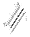
- FIG. 15 is a side view of the two card edge connectors densely arranged with each other in the front-to-back direction of FIG. 14 ;
- FIG. 16 is a perspective view of the card edge connector according to a third embodiment of the invention.
- FIG. 17 is an exploded perspective view of the card edge connector of FIG. 16 ;
- FIG. 18 is a further exploded perspective view of the card edge connector of FIG. 17 ;
- FIG. 19 is a cross-sectional view of the card edge connector of FIG. 16 ;
- FIG. 20 is a side view of the card edge connector according to a fourth embodiment of the invention.
- a card edge connector 100 includes an insulative housing 1 , a plurality of terminals 2 , two insulative fixing blocks 3 , an insulative cover 4 and a board lock 6 .
- the insulative housing 1 includes a pair of side walls 11 extending along a longitudinal direction, a mounting face 12 , a pair of towers 13 located at two opposite ends of the housing 1 and extending in a vertical direction perpendicular to the longitudinal direction.
- a central slot 14 is formed between the pair of side walls in the transverse direction perpendicular to both the longitudinal direction and the vertical direction.
- the housing 1 is obliquely mounted upon a printed circuit board with an acute angle formed between an exterior surface of the lower side wall and the mounting face 12 .
- the housing 1 essentially extends in a plane, which is defined by the longitudinal direction and the vertical direction, is perpendicular to the transverse direction while being oblique to the mounting face 12 .
- the tower 13 forms a receiving space 130 in which an ejector 5 is pivotally mounted.
- the tower 13 includes a lower/first part 131 and an upper/second part 132 .
- a width A of upper part 132 in the transverse direction is smaller than the width B of the lower part 131 .
- a pair of recesses (not labled) in the upper part 132 compared with the lower part 131 .
- the connector 100 is used to connect a module 800 to the printed circuit board 900 .
- the width A is defined between the exterior surface 133 of the upper part 132 and the exterior surface 134 of the upper part 132 .
- the housing 1 forms a front face 152 and the rear face 151 with a plurality of passageways 153 therebetween.
- the housing 1 further forms an upward face 111 and a downward face 112 .
- the housing further includes a key 161 to divide the central slot 14 , and a divider 162 corresponding the to key 161 .
- the terminals 2 are disposed in the passageways 153 by two sides of the central slot 14 .
- Each terminal 2 includes a base 21 retained to the corresponding side wall 11 , a contacting section 22 extending from one side of the base 21 into the central slot 14 , a mounting section 23 extending from the other side of the base 21 out of the housing 1 , and an extension 24 between the base 21 and the mounting section 23 .
- the upper row terminal 2 has a retention post (not labeled) beside the contacting section 22 while the lower row terminal 2 has the base 21 with barbs thereon for retention.
- the fixing block 3 is located between the tower 13 and the divider 162 and includes four rows of through holes 31 to receive the corresponding mounting section 23 of the terminals 2 .
- the cover 4 is mounted upon the housing 1 and the fixing blocks 3 to cover the extensions 24 .
- the cover 4 includes a hook 41 for securing to the housing 1 , a plurality of ribs 42 , a plurality of slots 43 for receiving the corresponding extensions 24 .
- the cover 4 has the same dimension with the housing 1 along the longitudinal direction so as to form at two longitudinal ends a pair of upward faces 44 with corresponding recesses thereof for accommodating a lower part 131 of the tower 13 of a front neighboring connector 100 when two neighboring connectors 100 are densely arranged with each other along a front-to-back direction on the printed circuit board.
- the ejector 5 includes a main body 51 , a kicker 52 extending from the lower portion of the main body 51 and into the central slot 14 , a handler 53 extending from the upper portion of the main body 51 , and a locker 56 extending from the upper portion of the main body 51 opposite to the handler 53 .
- the ejector 5 further includes a pair of pivotal shafts 54 for allowing the ejector 5 to be rotated in the receiving space 130 , and a pair of engagement blocks 56 for retaining to the corresponding tower 13 when the ejector 5 is located in the locking position.
- a board lock 6 is used for securing to the printed circuit board.
- the ejector 5 ′, the fixing blocks 3 ′ and board lock 6 ′ and terminals 2 are same with those in the first embodiment.
- the insulative housing 1 and the cover 4 ′ are different from those in the first embodiment wherein the cover 4 ′ is shortened along the longitudinal direction to be comply with only the side wall 11 ′ but leaving the cutouts 45 ′ in front of the corresponding tower 13 ′ in comparison with the recesses 44 in the cover 4 .
- the cover 4 includes a hook 46 ′ to be engaged within the corresponding hole 17 ′ in the housing 1 ′.
- the mounting sections 23 ′′ of the terminals 2 ′′ are mounted to the printed circuit board in a surface mounting manner rather than a through hole manner.
- the cover 4 ′′ further performs the tail retention function without the corresponding fixing blocks.
- the upper part 132 only has the downward recess for accommodating the bottom region of the lower part of the rear connector 100 when the two connectors 100 are densely arranged with each other in the front-to-back direction while the upward recess of the first embodiment no longer exists for increasing the strength of the tower 13 .
- the feature of the invention is to provide a recessed upper part of the tower so as to have the bottom region of the lower part of the tower of the rear card edge connector received within the recess of the upper part of the tower of the front card edge connector without interference when the front card edge connector and the rear card edge connector are densely arranged with each other in the front-to-back direction which is perpendicular to the longitudinal direction while being oblique to the transverse direction and the vertical direction.
- a recess is formed in a downward face of the upper part of the tower of the front card edge connector to receive an upward face of the bottom region of the lower part of the tower of the rear card edge connector as shown in FIG. 15 .
- Another feature of the invention is to have the upper side wall wider than the lower side wall in the transverse direction so as to have the terminals 2 in the upper side wall has the additional retention post beside the corresponding contacting section 22 in the transverse direction.
Abstract
Description
Claims (13)
Applications Claiming Priority (3)
| Application Number | Priority Date | Filing Date | Title |
|---|---|---|---|
| CN201610804262 | 2016-09-06 | ||
| CN201610804262.2 | 2016-09-06 | ||
| CN201610804262.2A CN107799935B (en) | 2016-09-06 | 2016-09-06 | Bayonet connector and combinations thereof |
Publications (2)
| Publication Number | Publication Date |
|---|---|
| US20180069334A1 US20180069334A1 (en) | 2018-03-08 |
| US10193253B2 true US10193253B2 (en) | 2019-01-29 |
Family
ID=61281373
Family Applications (1)
| Application Number | Title | Priority Date | Filing Date |
|---|---|---|---|
| US15/697,397 Active US10193253B2 (en) | 2016-09-06 | 2017-09-06 | Slanted type card edge connector assembly |
Country Status (3)
| Country | Link |
|---|---|
| US (1) | US10193253B2 (en) |
| CN (1) | CN107799935B (en) |
| TW (1) | TWI728170B (en) |
Cited By (6)
| Publication number | Priority date | Publication date | Assignee | Title |
|---|---|---|---|---|
| US11196198B2 (en) * | 2019-05-03 | 2021-12-07 | Foxconn (Kunshan) Computer Connector Co., Ltd. | Card edge connector with improved contacts |
| US20210408706A1 (en) * | 2019-08-10 | 2021-12-30 | Foxconn (Kunshan) Computer Connector Co., Ltd. | Electrical connector assembly |
| US20220085548A1 (en) * | 2020-09-11 | 2022-03-17 | Amphenol Commercial Products (Chengdu) Co., Ltd. | Robust and reliable high speed electrical connector assembly |
| US20220181809A1 (en) * | 2020-12-03 | 2022-06-09 | Foxconn (Kunshan) Computer Connector Co., Ltd. | Card edge connector |
| US20220216653A1 (en) * | 2020-09-01 | 2022-07-07 | Foxconn (Kunshan) Computer Connector Co., Ltd. | Cable connector with improved metallic shield |
| US20220263260A1 (en) * | 2019-07-19 | 2022-08-18 | Amphenol East Asia Electronic Technology (Shenzhen) Co., Ltd. | High reliability card edge connector with bottom seal |
Families Citing this family (3)
| Publication number | Priority date | Publication date | Assignee | Title |
|---|---|---|---|---|
| CN111064043B (en) * | 2018-10-16 | 2021-02-02 | 莫列斯有限公司 | Card edge connector |
| USD994615S1 (en) * | 2021-04-26 | 2023-08-08 | Yeonho Ms Co., Ltd. | Electrical connector |
| USD994616S1 (en) * | 2021-04-26 | 2023-08-08 | Yeonho Ms Co., Ltd. | Electrical connector |
Citations (24)
| Publication number | Priority date | Publication date | Assignee | Title |
|---|---|---|---|---|
| US4756694A (en) * | 1986-12-19 | 1988-07-12 | Amp Incorporated | Dual row connector for low profile package |
| US5013264A (en) * | 1989-09-25 | 1991-05-07 | Robinson Nugent, Inc. | Edge card connector having preloaded contacts |
| US5511985A (en) * | 1994-06-16 | 1996-04-30 | Burndy Corporation | Angled card edge connector |
| US5915979A (en) * | 1995-10-24 | 1999-06-29 | Berg Technology, Inc. | Electrical connector with stress isolating solder tail |
| US5931701A (en) * | 1996-12-04 | 1999-08-03 | Hon Hai Precision Ind. Co., Ltd. | Electrical connector assembly |
| US5961346A (en) * | 1997-07-30 | 1999-10-05 | Hon Hai Precision Inc. Co., Ltd. | Boardlock for use with slanted card edge connector |
| US5964606A (en) * | 1997-07-30 | 1999-10-12 | Hon Hai Precision Ind. Co., Ltd. | Structure of slanted DIMM connector for dense arrangement |
| US6116917A (en) * | 1998-03-18 | 2000-09-12 | Hon Hai Precision Ind. Co., Ltd. | Connector with floating spacer |
| US6168464B1 (en) * | 1998-01-30 | 2001-01-02 | Hon Hai Precision Ind. Co., Ltd. | Securement arrangement for slanted type card edge connector |
| US6176737B1 (en) * | 1995-02-24 | 2001-01-23 | Hon Hai Precision Ind. Co., Ltd. | Duplex connector assembly for use with plural cards |
| US6176723B1 (en) * | 1996-10-08 | 2001-01-23 | Hirose Electric Co., Ltd. | Electrical connector |
| US6203338B1 (en) * | 1997-05-10 | 2001-03-20 | Hon Hai Precision Ind. Co., Ltd. | Card edge connector assembly with ejectors for linear installation/ejection and the associated printed circuit board for use therewith |
| US6979206B2 (en) * | 2004-01-13 | 2005-12-27 | Hon Hai Precision Ind. Co., Ltd. | Card edge connector |
| US7473140B2 (en) * | 2006-09-05 | 2009-01-06 | Hon Hai Precision Ind. Co., Ltd. | Card edge connector |
| US20090291581A1 (en) * | 2008-05-23 | 2009-11-26 | Hon Hai Precision Industry Co., Ltd. | Electrical connector assembly for miniaturization |
| US7789681B2 (en) * | 2007-07-16 | 2010-09-07 | Hon Hai Precision Ind. Co., Ltd. | Card edge connector with an improved latch |
| CN202076454U (en) | 2011-03-31 | 2011-12-14 | 富士康(昆山)电脑接插件有限公司 | Inclined card edge connector |
| US20130040498A1 (en) * | 2011-08-12 | 2013-02-14 | Lotes Co., Ltd. | Electrical connector |
| US8398422B2 (en) * | 2010-06-08 | 2013-03-19 | Hon Hai Precision Ind. Co., Ltd | Card edge connector |
| US20130084723A1 (en) * | 2011-09-30 | 2013-04-04 | Hon Hai Precision Industry Co., Ltd. | Card edge connector |
| US8449334B2 (en) * | 2011-10-07 | 2013-05-28 | Lotes Co., Ltd. | Card edge connector |
| CN203225430U (en) | 2013-03-20 | 2013-10-02 | 富士康(昆山)电脑接插件有限公司 | An edge connector and a fixing member thereof |
| US8556662B2 (en) * | 2011-12-01 | 2013-10-15 | Proconn Technology Co., Ltd. | Card connector |
| US8747133B2 (en) * | 2011-11-02 | 2014-06-10 | Hon Hai Precision Industry Co., Ltd. | Card edge connector with improved lock mechanism |
Family Cites Families (5)
| Publication number | Priority date | Publication date | Assignee | Title |
|---|---|---|---|---|
| JPH10302863A (en) * | 1997-04-25 | 1998-11-13 | Molex Inc | Board-mounted electric connector |
| US6419503B1 (en) * | 2001-05-04 | 2002-07-16 | Hon Hai Precision Ind. Co., Ltd. | Alignment device for use with connector |
| US6830470B1 (en) * | 2003-06-20 | 2004-12-14 | Intel Corporation | Electrical device connector |
| CN103050820B (en) * | 2012-12-31 | 2016-05-25 | 华为技术有限公司 | A kind of double pin memory bar base connector and server |
| TWM463431U (en) * | 2013-04-03 | 2013-10-11 | Hon Hai Prec Ind Co Ltd | Card edge connector and retainer thereof |
-
2016
- 2016-09-06 CN CN201610804262.2A patent/CN107799935B/en active Active
-
2017
- 2017-08-16 TW TW106127735A patent/TWI728170B/en active
- 2017-09-06 US US15/697,397 patent/US10193253B2/en active Active
Patent Citations (25)
| Publication number | Priority date | Publication date | Assignee | Title |
|---|---|---|---|---|
| US4756694A (en) * | 1986-12-19 | 1988-07-12 | Amp Incorporated | Dual row connector for low profile package |
| US5013264A (en) * | 1989-09-25 | 1991-05-07 | Robinson Nugent, Inc. | Edge card connector having preloaded contacts |
| US5511985A (en) * | 1994-06-16 | 1996-04-30 | Burndy Corporation | Angled card edge connector |
| US6176737B1 (en) * | 1995-02-24 | 2001-01-23 | Hon Hai Precision Ind. Co., Ltd. | Duplex connector assembly for use with plural cards |
| US5915979A (en) * | 1995-10-24 | 1999-06-29 | Berg Technology, Inc. | Electrical connector with stress isolating solder tail |
| US6176723B1 (en) * | 1996-10-08 | 2001-01-23 | Hirose Electric Co., Ltd. | Electrical connector |
| US5931701A (en) * | 1996-12-04 | 1999-08-03 | Hon Hai Precision Ind. Co., Ltd. | Electrical connector assembly |
| US6203338B1 (en) * | 1997-05-10 | 2001-03-20 | Hon Hai Precision Ind. Co., Ltd. | Card edge connector assembly with ejectors for linear installation/ejection and the associated printed circuit board for use therewith |
| US5961346A (en) * | 1997-07-30 | 1999-10-05 | Hon Hai Precision Inc. Co., Ltd. | Boardlock for use with slanted card edge connector |
| US5964606A (en) * | 1997-07-30 | 1999-10-12 | Hon Hai Precision Ind. Co., Ltd. | Structure of slanted DIMM connector for dense arrangement |
| US6168464B1 (en) * | 1998-01-30 | 2001-01-02 | Hon Hai Precision Ind. Co., Ltd. | Securement arrangement for slanted type card edge connector |
| US6116917A (en) * | 1998-03-18 | 2000-09-12 | Hon Hai Precision Ind. Co., Ltd. | Connector with floating spacer |
| US6979206B2 (en) * | 2004-01-13 | 2005-12-27 | Hon Hai Precision Ind. Co., Ltd. | Card edge connector |
| US7473140B2 (en) * | 2006-09-05 | 2009-01-06 | Hon Hai Precision Ind. Co., Ltd. | Card edge connector |
| US7789681B2 (en) * | 2007-07-16 | 2010-09-07 | Hon Hai Precision Ind. Co., Ltd. | Card edge connector with an improved latch |
| US20090291581A1 (en) * | 2008-05-23 | 2009-11-26 | Hon Hai Precision Industry Co., Ltd. | Electrical connector assembly for miniaturization |
| US8398422B2 (en) * | 2010-06-08 | 2013-03-19 | Hon Hai Precision Ind. Co., Ltd | Card edge connector |
| CN202076454U (en) | 2011-03-31 | 2011-12-14 | 富士康(昆山)电脑接插件有限公司 | Inclined card edge connector |
| US20130040498A1 (en) * | 2011-08-12 | 2013-02-14 | Lotes Co., Ltd. | Electrical connector |
| US20130084723A1 (en) * | 2011-09-30 | 2013-04-04 | Hon Hai Precision Industry Co., Ltd. | Card edge connector |
| US8449334B2 (en) * | 2011-10-07 | 2013-05-28 | Lotes Co., Ltd. | Card edge connector |
| US8747133B2 (en) * | 2011-11-02 | 2014-06-10 | Hon Hai Precision Industry Co., Ltd. | Card edge connector with improved lock mechanism |
| US8556662B2 (en) * | 2011-12-01 | 2013-10-15 | Proconn Technology Co., Ltd. | Card connector |
| CN203225430U (en) | 2013-03-20 | 2013-10-02 | 富士康(昆山)电脑接插件有限公司 | An edge connector and a fixing member thereof |
| US9240640B2 (en) * | 2013-03-20 | 2016-01-19 | Hon Hai Precision Industry Co., Ltd. | Card edge connector with improved retainer and retainer thereof |
Cited By (10)
| Publication number | Priority date | Publication date | Assignee | Title |
|---|---|---|---|---|
| US11196198B2 (en) * | 2019-05-03 | 2021-12-07 | Foxconn (Kunshan) Computer Connector Co., Ltd. | Card edge connector with improved contacts |
| US20220263260A1 (en) * | 2019-07-19 | 2022-08-18 | Amphenol East Asia Electronic Technology (Shenzhen) Co., Ltd. | High reliability card edge connector with bottom seal |
| US20210408706A1 (en) * | 2019-08-10 | 2021-12-30 | Foxconn (Kunshan) Computer Connector Co., Ltd. | Electrical connector assembly |
| US11799223B2 (en) * | 2019-08-10 | 2023-10-24 | Foxconn (Kunshan) Computer Connector Co., Ltd. | Electrical connector assembly |
| US20220216653A1 (en) * | 2020-09-01 | 2022-07-07 | Foxconn (Kunshan) Computer Connector Co., Ltd. | Cable connector with improved metallic shield |
| US11831108B2 (en) * | 2020-09-01 | 2023-11-28 | Foxconn (Kunshan) Computer Connector Co., Ltd. | Cable connector with improved metallic shield |
| US20220085548A1 (en) * | 2020-09-11 | 2022-03-17 | Amphenol Commercial Products (Chengdu) Co., Ltd. | Robust and reliable high speed electrical connector assembly |
| US11824305B2 (en) * | 2020-09-11 | 2023-11-21 | Amphenol Commercial Products (Chengdu) Co., Ltd. | Robust and reliable high speed electrical connector assembly |
| US20220181809A1 (en) * | 2020-12-03 | 2022-06-09 | Foxconn (Kunshan) Computer Connector Co., Ltd. | Card edge connector |
| US11817645B2 (en) * | 2020-12-03 | 2023-11-14 | Foxconn (Kunshan) Computer Connector Co., Ltd. | Card edge connector having an insulative housing with recessed portions on outer surfaces thereof |
Also Published As
| Publication number | Publication date |
|---|---|
| CN107799935A (en) | 2018-03-13 |
| US20180069334A1 (en) | 2018-03-08 |
| TW201813206A (en) | 2018-04-01 |
| CN107799935B (en) | 2019-08-30 |
| TWI728170B (en) | 2021-05-21 |
Similar Documents
| Publication | Publication Date | Title |
|---|---|---|
| US10193253B2 (en) | Slanted type card edge connector assembly | |
| US9966679B2 (en) | Electrical connector having contacts with dual contacting beams thereof | |
| US9373905B2 (en) | Electrical card connector compatibly receiving two cards | |
| US10224653B2 (en) | Card edge connector having key equipped with metallic protective cap secured to housing | |
| US8444424B2 (en) | Card edge connector having improved ejector | |
| US9022809B2 (en) | Card edge connector | |
| US8147276B2 (en) | Electrical connector | |
| US8070499B2 (en) | Card edge connector with an improved retainer | |
| US9325090B2 (en) | Card edge connector with a metal member | |
| US7892006B2 (en) | Connector having an improved fastener | |
| US7828560B2 (en) | Card edge connector having an improved spacer | |
| US9172164B2 (en) | Card edge connector with an improved housing | |
| US8308513B2 (en) | Electrical connector | |
| US7677903B1 (en) | Board-to-board connector assembly | |
| US10720730B2 (en) | Card edge connector having metallic member formed integrally with insulative housing | |
| US8398422B2 (en) | Card edge connector | |
| US20120252276A1 (en) | Electrical card connector with contacts having shared soldering tail | |
| US7473140B2 (en) | Card edge connector | |
| US9312650B1 (en) | Plug connector, receptacle connector and electrical connector assembly | |
| US9806461B2 (en) | Card edge connector having improved ejector | |
| US8794985B2 (en) | Card Edge Connector | |
| US9240640B2 (en) | Card edge connector with improved retainer and retainer thereof | |
| US20050153585A1 (en) | Card edge connector | |
| US9627834B2 (en) | Electrical connector with improved fixing structure | |
| US8183155B1 (en) | Lower profile connector assembly |
Legal Events
| Date | Code | Title | Description |
|---|---|---|---|
| AS | Assignment |
Owner name: FOXCONN INTERCONNECT TECHNOLOGY LIMITED, CAYMAN IS Free format text: ASSIGNMENT OF ASSIGNORS INTEREST;ASSIGNORS:LI, ZHUANG-XING;TANG, WEN-JUN;BU, XUE-WU;REEL/FRAME:043511/0268 Effective date: 20170830 |
|
| FEPP | Fee payment procedure |
Free format text: ENTITY STATUS SET TO UNDISCOUNTED (ORIGINAL EVENT CODE: BIG.); ENTITY STATUS OF PATENT OWNER: LARGE ENTITY |
|
| STCF | Information on status: patent grant |
Free format text: PATENTED CASE |
|
| MAFP | Maintenance fee payment |
Free format text: PAYMENT OF MAINTENANCE FEE, 4TH YEAR, LARGE ENTITY (ORIGINAL EVENT CODE: M1551); ENTITY STATUS OF PATENT OWNER: LARGE ENTITY Year of fee payment: 4 |