US1018419A - Wood-distilling apparatus. - Google Patents
Wood-distilling apparatus. Download PDFInfo
- Publication number
- US1018419A US1018419A US47368409A US1909473684A US1018419A US 1018419 A US1018419 A US 1018419A US 47368409 A US47368409 A US 47368409A US 1909473684 A US1909473684 A US 1909473684A US 1018419 A US1018419 A US 1018419A
- Authority
- US
- United States
- Prior art keywords
- still
- stills
- flue
- wood
- pipes
- Prior art date
- Legal status (The legal status is an assumption and is not a legal conclusion. Google has not performed a legal analysis and makes no representation as to the accuracy of the status listed.)
- Expired - Lifetime
Links
- QTBSBXVTEAMEQO-UHFFFAOYSA-N Acetic acid Chemical compound CC(O)=O QTBSBXVTEAMEQO-UHFFFAOYSA-N 0.000 description 18
- OKKJLVBELUTLKV-UHFFFAOYSA-N Methanol Chemical compound OC OKKJLVBELUTLKV-UHFFFAOYSA-N 0.000 description 14
- 238000002485 combustion reaction Methods 0.000 description 10
- 239000007788 liquid Substances 0.000 description 8
- 239000002023 wood Substances 0.000 description 7
- CSCPPACGZOOCGX-UHFFFAOYSA-N Acetone Chemical compound CC(C)=O CSCPPACGZOOCGX-UHFFFAOYSA-N 0.000 description 5
- 238000010438 heat treatment Methods 0.000 description 5
- 238000010276 construction Methods 0.000 description 4
- 238000000197 pyrolysis Methods 0.000 description 4
- 235000008733 Citrus aurantifolia Nutrition 0.000 description 3
- 235000011941 Tilia x europaea Nutrition 0.000 description 3
- 239000002253 acid Substances 0.000 description 3
- 239000007789 gas Substances 0.000 description 3
- 239000004571 lime Substances 0.000 description 3
- 241000196324 Embryophyta Species 0.000 description 2
- XBDQKXXYIPTUBI-UHFFFAOYSA-M Propionate Chemical compound CCC([O-])=O XBDQKXXYIPTUBI-UHFFFAOYSA-M 0.000 description 2
- KXKVLQRXCPHEJC-UHFFFAOYSA-N acetic acid trimethyl ester Natural products COC(C)=O KXKVLQRXCPHEJC-UHFFFAOYSA-N 0.000 description 2
- FPIPGXGPPPQFEQ-OVSJKPMPSA-N all-trans-retinol Chemical compound OC\C=C(/C)\C=C\C=C(/C)\C=C\C1=C(C)CCCC1(C)C FPIPGXGPPPQFEQ-OVSJKPMPSA-N 0.000 description 2
- 238000004821 distillation Methods 0.000 description 2
- 206010022000 influenza Diseases 0.000 description 2
- 238000004519 manufacturing process Methods 0.000 description 2
- 238000000926 separation method Methods 0.000 description 2
- QTBSBXVTEAMEQO-UHFFFAOYSA-M Acetate Chemical compound CC([O-])=O QTBSBXVTEAMEQO-UHFFFAOYSA-M 0.000 description 1
- LFQSCWFLJHTTHZ-UHFFFAOYSA-N Ethanol Chemical compound CCO LFQSCWFLJHTTHZ-UHFFFAOYSA-N 0.000 description 1
- 244000261422 Lysimachia clethroides Species 0.000 description 1
- 240000008881 Oenanthe javanica Species 0.000 description 1
- 235000019169 all-trans-retinol Nutrition 0.000 description 1
- 239000011717 all-trans-retinol Substances 0.000 description 1
- 238000000034 method Methods 0.000 description 1
- 230000003472 neutralizing effect Effects 0.000 description 1
- 239000000126 substance Substances 0.000 description 1
- XLYOFNOQVPJJNP-UHFFFAOYSA-N water Substances O XLYOFNOQVPJJNP-UHFFFAOYSA-N 0.000 description 1
Images


Classifications
-
- C—CHEMISTRY; METALLURGY
- C02—TREATMENT OF WATER, WASTE WATER, SEWAGE, OR SLUDGE
- C02F—TREATMENT OF WATER, WASTE WATER, SEWAGE, OR SLUDGE
- C02F1/00—Treatment of water, waste water, or sewage
- C02F1/02—Treatment of water, waste water, or sewage by heating
- C02F1/04—Treatment of water, waste water, or sewage by heating by distillation or evaporation
-
- B—PERFORMING OPERATIONS; TRANSPORTING
- B01—PHYSICAL OR CHEMICAL PROCESSES OR APPARATUS IN GENERAL
- B01D—SEPARATION
- B01D1/00—Evaporating
- B01D1/30—Accessories for evaporators ; Constructional details thereof
- B01D1/305—Demister (vapour-liquid separation)
Definitions
- Fig. 3 is a secthe otherwise wasted heatfrom a retort.
- furnace such as is used for the dry distillation'of wood in the manufacture of Apyroligneous acid, may be utilized as one means for heatin the stilll lin which said pyroligneous acid after being neutralized is distilled.
- a ⁇ further object is to provide means Awhereby the heated products of combustion from said furnace may-be directed, either into intimate'contact with the walls of the still, or may be more or less directed into the stack without coming in contact with the still walls.
- a further object is to provide means whereby the liquid to be treated may be preheated before it enters the still, and also' to provide means whereby steam may be intro pokerd into the interior of the'still to assist lin heating the liquid therein.
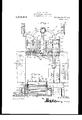
- igure 1 is a ,top plan view of a -woodl
- Fig. 2 is a section tion on the line 3-3 Vof Fig. 1.
- Fig. el isa .section on the line 4 4 ofFig. 1.
- Fig. 5 is an enlarged horizontal section of a portion of the distilling plant shown in Fig. 1.
- Fig. 6 is a erspective view of one of the stills.
- Fig. 7 1s a like view 4o one of the stills, the steam pipes entering the same and passin between the legs of the same being remove
- Correspondingand like parts are' referred to in the following descriptionand indicated 60v in all'theviews ofthe drawings by the same reference characters.
- my invention is not limited to the' production of Wood alcohol.
- the destructive distillation of wood produces inammable gases, a strongly acid idistillate, and a certam quantity of tar.”
- the aqueous distillate contains methyl alcohol, acetic acid, acetone and methyl acetate, the distillate being known as pyroligneous acid.
- the tar and pyroligneous acid are drawn oli' and neutralized with lime, thus separating therefrom the acetic acid.
- A designates retort' furnaces having the usual construction otthpse designed for destructive distillation. From these retort furnaces A the gas, the acid distillate and the tar are carrled to con densers (not illustrated inthe drawing). The tar and pyroligneous acid are allowed to stand and separate in suitable vesseils, ⁇ j which are not illustrated, however, as being ⁇ no part of my invention, and the pyroligneous acid is then neutralized with lime by any suitable apparatus .and is then, by means.
- FIG. 1 One of the stills 2 is illustrated in Figs. ,4, 6 and 7.
- Each still consists of a hollow body or casing, the lower portion of which, is formed with a plurality of downwardly extending legs or compartments 10, the ,legs being spacedor separated from each other by longitudinally extending passages 9 which are open at both ends.
- Figs. 4 and 5 The pipes 3 from the storage tanks 3 enter the wallV 3X and pass, each into a-passage 9 between two adjacent legs of each still.
- Each. ⁇ pipe is formed into a series of coils 3b extending up to the upper end of the passage 9.
- the pipe then extends out from the rear end of the passage and is carried upward over the top of thestill and then downward into the upper portion of the still, as at 3 (see Figt/l)
- This arrangement ofthepipe providesy for preheating the liquid to be distilled Abefore fore not shown in detailg In these condens its entranceinto the body 'of the still.
- Each of the stills 2 is rconnected by apipe or gooseneclri to condensers '5 which may be of any desiredcharacter and which are thereers -the volatile methyl alcohol, together w ith water, is condensedinto crude wood spirit.
- This crude wood spirit may be again dis* tilled, andfor this; purpose the crude wood spirit may be placed inthe tanks 6 from which it will pass bythe pipes 6a into the stills '7, from which it is carried to the condensers 5*.
- the 'stills 7, are precisely similar Vin construction t'o the stills 2, and the pipes 6a each ente'rlone fof the compartments of the corresponding still, are coiled in these compartments and extend up over the compartinentsv as at 6F, precisely as do 4the pipes 3.'
- dampers 15 having the form of gates or shutters and located at the openings of the passages l0. VThese dempers when turned in one direction will prevent the passage of heated air into the spaces between the legs of the flue l2 into convenient ⁇ position for actua-v tion, these handles being connected each to a plurality of dempers.
- damper 17 A In addition to the dampers l5 which control the passage of Vheat between the legsv of the still, I have also provided a three'- way damper 17 Aarranged in the flue 12 at the junction of said flue with the lue 18.
- This damper has the form of two vanes at right angles toeach other and may be rotated in a complete circle and thus turned 'so as to close ott the liue 18, leaving the transverse flue entirely open from end to end, or may be shifted to Aclose oli one end of the transverse flue, leaving the other .end
- goosenecks 4' both of said'sets of stills may be closed soY f thatA theheat may freely pass', along the flue 12 and so directly out through the Hue v18 to the stack.
- Conducting pipes 19 pass from these steam boilers and connect with a transversely extending pipe 20 which as shown is located l above the lue 12. ⁇
- This pipe 20 has 'extending through it the branch pipes 21. -There is one of these branch pipes for each of the 20 compartments or legs of the still.
- the pipes A21 extend downward from the pipe .20 and enter the legs of the still, and within thesel vlegs are each formed a coil extending longiv.tudinally through theinterio'r of the legs, 25 the extremity of the coil being conducted out of the leg and carried back to the boiler by the return pipes 22 and 23, as clearly shown in dotted lines in 4l ⁇ ig.4f and in full 'lines in Fig. '6.
- 1 In order to cut off heat passing out through the flue 11 or to regu-- .late the passage of the heated products' therethrough, 1 provide the damper 25 which, as shown in Fig. 5, ⁇ is located at the junction of. the fiue 11 with the flue 12 and which is operated in any suitable manner.
- a Y still provided in its lower portion with a' seri'esfof'open-'ended passages, said passages dividing the lower portion of the -still into afiserlies ⁇ ofA compartments, afurnace, means for conducting a ⁇ heating medium into thev passages between the 1 comprovi'd'ed in its lowerl portion 4 partments, and a liquid supply pipe lead ⁇ ing linto said still, said supply pipe enter-- ing one of said passages' in the bottom of the first named flue either into the sti the still, being coiledtherein,v and thenfbef ⁇ ing extended into the still, whereby the liquid therein may be, pre-heated.
- a still In apparatus of the character described, a still, a casing surroundingL the still, a furnace,a stack, a flue leading, from the furnace to the stack and communlcating with the casing of the still, me'ans for cuttin olf communication between said iue an the interiorof the casing, and a flue leading from the casing to the stack.
- two batteries of stills each batteryl being surrounded by a casing, a furnace, a transverse flue communicating with the furnace and vextending entirely across the fronts of the still casings, said transverse flue communicating with the casings,means whereby the communication may be cut oi between the transverse flue and thecasings, iues leading from-the rear ends of the still casings to a commondischarge stack, and a middle discharge fluem'extending between the pairs of still dcasings, connected at one end to the middle of the transverse iue and at ythe other connected to said stack, and.
- valves' in the transverse flue whereby the products of combustion from the furnace maybe shut ofi' from. the intermediate Hue orfrom either end 'of the ⁇ transverse flue.
Landscapes
- Chemical & Material Sciences (AREA)
- Life Sciences & Earth Sciences (AREA)
- Hydrology & Water Resources (AREA)
- Engineering & Computer Science (AREA)
- Environmental & Geological Engineering (AREA)
- Water Supply & Treatment (AREA)
- Organic Chemistry (AREA)
- Chemical Kinetics & Catalysis (AREA)
- Fats And Perfumes (AREA)
Description
R. W. HILTON.
WOOD DISTILLING APPARATUS.
2 1 9 l wf.. .2 b. 8 F d 8 lo n e LIU n@ P QM O g Zy 2 N. A J D E u F .N o I T A w L. P D.. A
SSHEBTS--SHBE'I' 1.
' Summa/gr,
ro soul/R R. W. HILTON. WOOD DISTILLING APPARATUS.
APIPLIOATION FILED JAN. z'zX 1909,
Patented Feb. 27, 1912.
3 SHEETS-SHEET 24 guna/nto@ .R. W. HILTON.
WOD DISTILLING APPARATUS.
APyLIoATIoN FILED @11.22, 1909.
Patented Feb. 27, 1912.V
3 SHEETS-SHEET 3.
. i wvwrntofo ROBERT W. HIIJTONfOF SME'I'HPORT, PENNSYLVANIA.
WOOD-DISTILLING APPARATUS.
Spec'ication of Letters iatent.
Patented Feb. 27, 1912.
Application liled January 22, 1909. Serial No. 473,684.
To all whom it may concern.'
Be it known that I, Rom-:RT W. .Hnnom citizen of the United States, res1d1ng at Smethport, in the county o f McKean and Y State of Pennsylvania, have invented certain new andy useful Improvements in lood- Distilling Apparatus, of which the follo-wing is a speciication.
jThis invention relates to distilling appa ratus and more particularly to -a peculiar form of still and to means'designed to secure:
important advantages in the application of heat tothe still, the primary object of the invention being to provide means whereby valcohol distilling pla on the line 2 2 of Fig. 1. Fig. 3 is a secthe otherwise wasted heatfrom a retort.
furnace, such as is used for the dry distillation'of wood in the manufacture of Apyroligneous acid, may be utilized as one means for heatin the stilll lin which said pyroligneous acid after being neutralized is distilled.
' A` further object is to provide means Awhereby the heated products of combustion from said furnace may-be directed, either into intimate'contact with the walls of the still, or may be more or less directed into the stack without coming in contact with the still walls.-
A further object is to provide means whereby the liquid to be treated may be preheated before it enters the still, and also' to provide means whereby steam may be intro duced into the interior of the'still to assist lin heating the liquid therein.
My inventionis shown in the accompanyindrawings wherein.:
igure 1 is a ,top plan view of a -woodl n Fig. 2 is a section tion on the line 3-3 Vof Fig. 1. Fig. elisa .section on the line 4 4 ofFig. 1. Fig. 5 is an enlarged horizontal section of a portion of the distilling plant shown in Fig. 1. Fig. 6 is a erspective view of one of the stills. Fig. 7 1s a like view 4o one of the stills, the steam pipes entering the same and passin between the legs of the same being remove Correspondingand like parts are' referred to in the following descriptionand indicated 60v in all'theviews ofthe drawings by the same reference characters. In order that my invention may be underi stood, it is necessary to refer briefly to the bein borne in mind, however, that my invention is not limited to the' production of Wood alcohol.
The destructive distillation of wood produces inammable gases, a strongly acid idistillate, and a certam quantity of tar." The aqueous distillate contains methyl alcohol, acetic acid, acetone and methyl acetate, the distillate being known as pyroligneous acid. The tar and pyroligneous acid are drawn oli' and neutralized with lime, thus separating therefrom the acetic acid.
By the -usual process, 'the pyroligneous acid with as little tar as possible is drawn off from the crude distillate obtained from the wood retort and is cleared from tar as far as possible by subsidence. To the super-A natant liquor which contains a little tar and the crude acetic acid, alcohol, 'acetone and methyl acetate is added lime for the purpose Aof neutralizing the acetica'cid and convertspirit is distilled o'from the solution containing the impure acetate and the tarry substance. I have therefore not shown'kin the drawings any apparatus for thejcondt-l sation of the vapor from the wood retorts,
nor have I shown any apparatus for the separation of tar, or. for the separation'tgf acetic acid.
In the drawings A designates retort' furnaces having the usual construction otthpse designed for destructive distillation. From these retort furnaces A the gas, the acid distillate and the tar are carrled to con densers (not illustrated inthe drawing). The tar and pyroligneous acid are allowed to stand and separate in suitable vesseils,` j which are not illustrated, however, as being` no part of my invention, and the pyroligneous acid is then neutralized with lime by any suitable apparatus .and is then, by means.
of pipes which it is unnecessary to illustrate, conveyed to storage'tanks 3 from which the liquid is conve ed to the stills 2 b y conducting pipes 3. It is 'in these stills 2.an'd vthe means whereby they are heated and the heat centrelld, that my invention lies- One of the stills 2 is illustrated in Figs. ,4, 6 and 7. Each still consists of a hollow body or casing, the lower portion of which, is formed with a plurality of downwardly extending legs or compartments 10, the ,legs being spacedor separated from each other by longitudinally extending passages 9 which are open at both ends. It Will be understood that these legs or compartments 10 `open into the body of the stills 2, 3, the lower portion'V of the still,- or preferably the lower portions of two conjoined stills, is inclosed within a Wall 2", the rear end of this Wall being spaced from therear end of the still, as
shown in Figs. 4 and 5. The pipes 3 from the storage tanks 3 enter the wallV 3X and pass, each into a-passage 9 between two adjacent legs of each still. Each.` pipe is formed into a series of coils 3b extending up to the upper end of the passage 9. The pipe then extends out from the rear end of the passage and is carried upward over the top of thestill and then downward into the upper portion of the still, as at 3 (see Figt/l) This arrangement ofthepipe providesy for preheating the liquid to be distilled Abefore fore not shown in detailg In these condens its entranceinto the body 'of the still.
Each of the stills 2 is rconnected by apipe or gooseneclri to condensers '5 which may be of any desiredcharacter and which are thereers -the volatile methyl alcohol, together w ith water, is condensedinto crude wood spirit. This crude wood spirit may be again dis* tilled, andfor this; purpose the crude wood spirit may be placed inthe tanks 6 from which it will pass bythe pipes 6a into the stills '7, from which it is carried to the condensers 5*. The 'stills 7, are precisely similar Vin construction t'o the stills 2, and the pipes 6a each ente'rlone fof the compartments of the corresponding still, are coiled in these compartments and extend up over the compartinentsv as at 6F, precisely as do 4the pipes 3.'
"As a1 means for heating the stills, the
products -of 'combustion and heating gases romthe retort furnaces Whiclfwould be otherwise vwasted, are conducted from the re tort urnacesA tov a transverse flue 12 which extends across theA entire front of the batteryjof stills and connects the retort furfof combustib@ from the steam V'boli er furmeyals be' utiliz-,effi for heating the f stills. The heated products of combustion from the retort furnaces and from the steam boiler` furnace are conducted into the Hue 12 and from thence conducted between the legs of the several stills, the heat passing beneath the bottoms of the stills and around the ends and'sides thereof. The products of combustion the-nce pass into .flues- 13 which lead to a stack .1.4i 'from'which the products of com` vbustion are discharged after they have yielded a large portion of their heat. It will be seen that by this arrangement the combined heat of the retort furnaces and of the steam boiler furnace passes beneath the bottoms of the stills, and around the ends and sides thereof and that thus a very large superficial area of still is subjected to this heat, .and that the heat which would be ordinarily Wasted and discharged Without doing its full work, is made to do service in heating the stills for the final distillation. The transverse 'flue 12 is also connected to the stack 14 by means of an' intermediate flue 18. In order to control or regulate. the passage of hot products of combustion through and around the legs of the stills, I provide dampers 15 having the form of gates or shutters and located at the openings of the passages l0. VThese dempers when turned in one direction will prevent the passage of heated air into the spaces between the legs of the flue l2 into convenient` position for actua-v tion, these handles being connected each to a plurality of dempers.
These dempers and operating levers are very simply 'shown in the drawing for the reason that any form of dempers may be used for this purpose, as 'will be understood by those skilled in the art.
In addition to the dampers l5 which control the passage of Vheat between the legsv of the still, I have also provided a three'- way damper 17 Aarranged in the flue 12 at the junction of said flue with the lue 18. This damper has the form of two vanes at right angles toeach other and may be rotated in a complete circle and thus turned 'so as to close ott the liue 18, leaving the transverse flue entirely open from end to end, or may be shifted to Aclose oli one end of the transverse flue, leaving the other .end
of the flue 12 connected to the flue 18, or this damper maybe" so turned that-'both ends of the *flue 12, are in communication with each other and also with the, flue 18.
' .'t'jthe, goosenecks 4' both of said'sets of stills may be closed soY f thatA theheat may freely pass', along the flue 12 and so directly out through the Hue v18 to the stack.
In' addition to the features above described, I have provided means whereby the liquid inthe still is heated by steam'pipes which extend into the compartment-s 10. For this purpose I provide the steam boilers 5 .of an usual ,or ordinary construction. Conducting pipes 19 pass from these steam boilers and connect with a transversely extending pipe 20 which as shown is located l above the lue 12.` This pipe 20 has 'extending through it the branch pipes 21. -There is one of these branch pipes for each of the 20 compartments or legs of the still. The pipes A21 extend downward from the pipe .20 and enter the legs of the still, and within thesel vlegs are each formed a coil extending longiv.tudinally through theinterio'r of the legs, 25 the extremity of the coil being conducted out of the leg and carried back to the boiler by the return pipes 22 and 23, as clearly shown in dotted lines in 4l `ig.4f and in full 'lines in Fig. '6.
It will thus be seen that the still is heated I. v. Q'In the practical'opelation of my inventionl 'ithe ,liquid thejtanks 3 is conducted by the v .ipes `3] into the' coils 3b Whereitfius preeated byheatentering the casing-Qtfrom 45.jtheilue-12. Alfter. beingy preheated theiiiquid inthe'pipe's 3 a'n'd3"A is conducted upl and .dischargedinto the upper end of the main body/,of the still-2. [Here itv is heated by the j- '.gsteam pipes y 21 which pass through the legs,
andby'the heat o f the'pi'oducts of combustion pipes passin from the retort furnaces 'andthe-'boiler urnace between the legs, T The vapor from the steam passes'oll lthrough and is carried to the con- 5 denserslx L .i v hot products of combustion fronrthe retort furnaces Aare carriedinto the trans- "verse, ilue 12.v From ,this flue they-may be @directed-either between the legs of the still and through the interior of. the casing 2` and thence'by way of the flue 13 to the stack,`
or by shutting olf thedampers 15 the products of combustion may be carried to the,
`Hue 18 and vpass directly outward tothe stack. Byl operating the damper 17 it is not'only by the passage of theheat products The steam itself'does not` possible to cut olf either pair of the stills and `take the heat entirely from one of the retort furnaces and passit'around one of the. pairs of stills and not around the other, or the flue 18may beentirely cut oand every Vparticle of the heat passing from the retort furnaces, or thesteam furnaces may be car- A.ried into the casing 2.* through and around the legs of the still. In order to cut off heat passing out through the flue 11 or to regu-- .late the passage of the heated products' therethrough, 1 provide the damper 25 which, as shown in Fig. 5,`is located at the junction of. the fiue 11 with the flue 12 and which is operated in any suitable manner.
It'isto be understood that -my invention' is not` limited to .any particular number of stills or to otherimmaterial features disclosed in the drawings, or to lany particular size or proportion of `arts, and that various changes might be ma e in the details of construction and the arrangement of these parts without departing from the spirit of the inlvention. s.
-While I have described'my improved still as being used in connection with a plant for Athe destructive distillation of Wood, I wish it understood that the improved still andthe means for heatin the/same may be used /forthe distillation 0% any product.
Having thus described the invention, what I c laimis 1. In napparatus of thel character de-i scribed, a still provided in its lowerj p'ortion with a plurality of'transversely' ex-A tending passages,.s`aid passages dividingl the lower portion ofthestilll in to aseries of dep'endmg compartmenta'f-steam pipes enteringthe several compartments eX- f1 i tending through the same, andmeans for' 195.
carrying" heat'in'dependently of: the stea-'m pipes. into the passages betweenv said .com-4 partments.
2. In apparatus scribed, 'a' stlll with a series o transversely extending passages, said vpassages, dividing the lower portionof thestill into a series of `depending "of characterf'de# compartments, steam' pi es entering thesecompartments and coile therein and then" passing out of the compartments, .a furnace,andjmeans for conducting the prodyuctsfof'scombustion from vthe furnace intov thepassag'es between the compartments beneath the'still.` v
3. .Iny apparatus of the character decri-bed, a Y still. provided in its lower portion with a' seri'esfof'open-'ended passages, said passages dividing the lower portion of the -still into afiserlies` ofA compartments, afurnace, means for conducting a `heating medium into thev passages between the 1 comprovi'd'ed in its lowerl portion 4 partments, and a liquid supply pipe lead` ing linto said still, said supply pipe enter-- ing one of said passages' in the bottom of the first named flue either into the sti the still, being coiledtherein,v and thenfbef` ing extended into the still, whereby the liquid therein may be, pre-heated. y
4. In apparatus of the character described, a still, a casing surroundingL the still, a furnace,a stack, a flue leading, from the furnace to the stack and communlcating with the casing of the still, me'ans for cuttin olf communication between said iue an the interiorof the casing, and a flue leading from the casing to the stack.
5. In apparatus of the character described, a plurality of stills, casings inclosing the stills, a furnace, a Hue extending entirely across the fronts of the still casings and communicating with the urnace a stack with which said flue is connected, flues leading from the rear ends of the still casings to said stack, and means for diverting the products of combustion passing into p l cas-j ings or into the stack. y
6. In apparatus of the character dev scribed, two batteries of stills, each batteryl being surrounded by a casing, a furnace, a transverse flue communicating with the furnace and vextending entirely across the fronts of the still casings, said transverse flue communicating with the casings,means whereby the communication may be cut oi between the transverse flue and thecasings, iues leading from-the rear ends of the still casings to a commondischarge stack, and a middle discharge fluem'extending between the pairs of still dcasings, connected at one end to the middle of the transverse iue and at ythe other connected to said stack, and.
valves' in the transverse flue whereby the products of combustion from the furnace maybe shut ofi' from. the intermediate Hue orfrom either end 'of the `transverse flue.
In testimony whereof I aftiix-my signature in presence'of two witnesses.-
ROBERT w. HILTON. [ala] Witnesses: *i
J. CLAYTON BAcnUs, F. H. HUNGIvlLLE.
Copies of, this patent mayv be obtained for v-e dents each, by addressingV the Commissioner of Patents,
' yWashington, D. C. i
Priority Applications (1)
| Application Number | Priority Date | Filing Date | Title |
|---|---|---|---|
| US47368409A US1018419A (en) | 1909-01-22 | 1909-01-22 | Wood-distilling apparatus. |
Applications Claiming Priority (1)
| Application Number | Priority Date | Filing Date | Title |
|---|---|---|---|
| US47368409A US1018419A (en) | 1909-01-22 | 1909-01-22 | Wood-distilling apparatus. |
Publications (1)
| Publication Number | Publication Date |
|---|---|
| US1018419A true US1018419A (en) | 1912-02-27 |
Family
ID=3086721
Family Applications (1)
| Application Number | Title | Priority Date | Filing Date |
|---|---|---|---|
| US47368409A Expired - Lifetime US1018419A (en) | 1909-01-22 | 1909-01-22 | Wood-distilling apparatus. |
Country Status (1)
| Country | Link |
|---|---|
| US (1) | US1018419A (en) |
-
1909
- 1909-01-22 US US47368409A patent/US1018419A/en not_active Expired - Lifetime
Similar Documents
| Publication | Publication Date | Title |
|---|---|---|
| US1018419A (en) | Wood-distilling apparatus. | |
| US1886621A (en) | Cracking still and process | |
| US1945581A (en) | Oil refining | |
| US737067A (en) | Mechanism for the reduction of pyroligneous acids. | |
| US1058850A (en) | Steam-generator. | |
| US507230A (en) | laird | |
| US525552A (en) | Feed-water heater | |
| US1508136A (en) | Economizer | |
| US1753432A (en) | Art of cracking hydrocarbons | |
| US281946A (en) | Sectional steam-generator | |
| US1901730A (en) | Boiler | |
| US1714963A (en) | Process of producing gasoline from solid material | |
| US384725A (en) | Apparatus for distilling fatty acids | |
| US635647A (en) | Kiln for burning fire-brick, &c. | |
| US1547993A (en) | Pressure still | |
| US525551A (en) | Feed-water heater | |
| US1658819A (en) | Steam generator | |
| US1473402A (en) | Process of refining oil | |
| US1287922A (en) | Feed-water heater. | |
| US401276A (en) | Processing apparatus | |
| US1202823A (en) | Process of reducing crude petroleum. | |
| US766889A (en) | Water-heater. | |
| US465077A (en) | And james ii | |
| US1513384A (en) | System and apparatus for refining oil | |
| US314368A (en) | Appaeatus foe the distillation of htdeocaebons |