US1018171A - Leather-scarfing machine. - Google Patents
Leather-scarfing machine. Download PDFInfo
- Publication number
- US1018171A US1018171A US57075310A US1910570753A US1018171A US 1018171 A US1018171 A US 1018171A US 57075310 A US57075310 A US 57075310A US 1910570753 A US1910570753 A US 1910570753A US 1018171 A US1018171 A US 1018171A
- Authority
- US
- United States
- Prior art keywords
- leather
- roll
- knife
- movement
- cam
- Prior art date
- Legal status (The legal status is an assumption and is not a legal conclusion. Google has not performed a legal analysis and makes no representation as to the accuracy of the status listed.)
- Expired - Lifetime
Links
- 239000010985 leather Substances 0.000 description 41
- 239000011435 rock Substances 0.000 description 9
- 238000010276 construction Methods 0.000 description 3
- 210000003746 feather Anatomy 0.000 description 2
- 230000002459 sustained effect Effects 0.000 description 2
- 230000015572 biosynthetic process Effects 0.000 description 1
- 238000012840 feeding operation Methods 0.000 description 1
- 230000001105 regulatory effect Effects 0.000 description 1
Images

Classifications
-
- C—CHEMISTRY; METALLURGY
- C14—SKINS; HIDES; PELTS; LEATHER
- C14B—MECHANICAL TREATMENT OR PROCESSING OF SKINS, HIDES OR LEATHER IN GENERAL; PELT-SHEARING MACHINES; INTESTINE-SPLITTING MACHINES
- C14B1/00—Manufacture of leather; Machines or devices therefor
- C14B1/02—Fleshing, unhairing, samming, stretching-out, setting-out, shaving, splitting, or skiving skins, hides, or leather
- C14B1/14—Fleshing, unhairing, samming, stretching-out, setting-out, shaving, splitting, or skiving skins, hides, or leather using tools cutting the skin in a plane substantially parallel to its surface
Definitions
- This invention relates to leather-scarfing machines of that type wherein a stationary knife is used and the scarfing operation is performed by moving the leather transversely of the cutting edge of the knife at the same time that it is moved longitudinally.
- One object of our invention is to provide a machine of this type which will cut the scarf so that the edge thereof will be comparatively thick instead of tapering to a knife edge, and sothat at the point where the scarf begins the leather will be cut to form a gouge or shoulder, all as will be more fully hereinafter described and claimed.
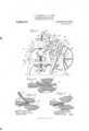
- Figure 1 is a side view of the machine embodying the invention
- Figs. 2, 3 and 4 are views showing the manner in which the scarf is made
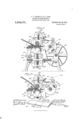
- Fig. 5 is a top plan view of the machine
- Fig. 6 is an edge view
- Fig. 7 is a side view of the cam for giving transverse movement to the feed rolls
- Fig. S is a view showing the manner in which the two pieces of leather scarfed on our machine may be spliced together
- Fig. 9 is a section on the line m-m, Fig. 5
- Fig. 10 is a section similar to Fig. 9 showing the parts in diiferent position
- Fig. 11 is a section on the line g/-g/, Fig. 6
- Fig. 12 is an enlarged view of two scarfed ends of leather applied to each other as they would be in making a joint.
- the scariing of the leather is accomplished by a knife 3 which is stationary and the leather to be scarfed is fed forward against the knife by means of two feed rolls 4, 5.
- the knife is shown as supported by a holder 6 which is adjustably carried by the frame 7 of the machine.
- This holder is received between the two side pieces 8 of the frame and is held in position by two screws 9 that pass through the side pieces into the sides of the holder.
- Said holder is adapted to be adjusted into different angular positions so as to vary the angular position of the cutting edge of the knife, and for this purpose said holder is provided with the arm 10 having the curved slot 11 which is concentric with the screws 9 and through which enters a clamping screw 12 secured inthe side of the frame. By loosening the clamping screw the holder may be turned about the bolts 9, as will be obvious, thus changing the angular position of the knife.
- the knife is slotted as usual and is clamped to the holder by clamping screws 14, this construction providing for adjustment of the knife toward and from the feeding rolls.
- the roll 5 is in the nature of a presser-roll, and the roll 4 is positively actuated for feeding the leather 15 forward.
- the surface of the roll 4 may be roughened if desired for facilitating the feeding operation.
- Said oscillating roll 4 isjournaled in two boxes or bearings 16 that are slidably mounted in slots 17 formed in the sides of the frame, and this roll is yieldingly supported by springs 19 which encircle guide-pins 2O depending from the boxes and which bear on the bushings 21 that are screw-threaded into the base of the frame.
- the guide-pins 20 extend down through the bushings and are guided thereby, and each guide-pin carries' at its lower end a headed screw 22 which passes through a bracket 23, the head 24 of the screw acting to'limit the upward movement of the guide-pins 2O and boxes 16 by its engagement with said bracket.
- the roll 5 is sustained in two boxes 25 that are also mounted in the slot 17, and we will preferably employ springs 26 between the boxes, which springs operate normally to elevate the roll 5.
- the roll 4 may be oscillated in any suitable way, although we have herein shown for this purpose an arm 27 fast on the en d raten-tea Feb. 2o, i912.
- each box 25 has extending therefrom a projection preferably in the form of a screw 37, and these projections 87 are acted on by rolls 88 carried by arms 38 rigid with a rock shaft 40.
- the shaft 40 has extending therefrom another arm 4i carrying a roll at its end which is adapted to be engaged by a.
- cam member 42 mounted on the shaft 88, said cam member being constructed and timed to rock the shaft 40 thereby to depress the upper roll during the forward feeding movement of the roll 4.
- the roll 5 is normally elevated from the roll 4 by the springs 2G suriiciently to permit the piece of leather 15 to be scarfed to be inserted between the rolls, as seen in Figs. 2 and 9, an adjustable gage 45 being provided to properly position the leather.
- the machine starts to operate the first movement is to depress the roll 5 ⁇ onto the leather l5 and then to force hoth rolls and the leather downwardly to bring the leather hard against the edge of the knife, as shown in Fig. 2.
- the roll 4 begins its forward feeding movement and during such movement the cam 42 continues the rocking movement of the shaft 40 and the consequent downward movement of the rolls transversely to the cutting edge of the knife, thereby causing the knife to cut diagonally through the leather 15.
- the leather will be cut, as shown in Fig. 8, that is, the knife will first cut a sort of gouge 48 in the work and thereafter said knife will cut straight through the work diduced.
- the cam 42 for giving this lateral movement to the rolls 4 and 5 is especially made so as to permit the scarf to be of different lengths and so as to make more or less of a gouge 48 at the beginning of the scarf, as desired.
- the cam 42 with the adjustable section 50 which is arranged so that the eccentricity thereof can be varied, as well 'as the abruptness of the rise thereof.
- this cam section 50 is pivoted at one end upon the eccentric portion 5l of a pin 52 that is mounted in a boss 58 formed on the cam member 42, said pin having the thumb-piece 54 by which it may be turned.
- this pin 51 will throw the end 55 of the cam section 50 radially or toward and from the axis of the cam 42.'
- the other end of the cam section 50 rests on the end of the adjusting screw 5G which is screw-threaded into the body of the cam 42 so that by manipulating said screw 56 the end 57 of the cam section may be thrown toward or from the center.
- the length of the scarf depends upon the eccentricity of the surface of the cam section 50 and this depends upon the adj ust-ment of the screw 5G.
- the main portion of the cam member 42 is concentric and the movement of the roll 5 against the leather and that of the leather against the knife blade before the roll 4 begins its movement is accomplished by the end 55 of the cam section and by adjusting the pin 52 the amount of the initial movement of the rolls transversely of the knife can be regulated and thereby the depth of the gouge 48.
- We will preferably provide the slot 90 and lever 29 with the curved or concentric portion 91 so that the roll 4 will remain at rest while the roll 5 is being brought against the leather and the leather against the knife blade and so that the forward feeding movementof the roll 4 will not occur until after the leather is firmly pressed against the cutting edge of the knife.
- a leather-Scarfing machine the combination with a knife, of a feeding roll movable toward the knife in a direction transverse to the direction of feed, a rocking member to give transverse movement to the roll, a shaft for operating the feed roll, al cam on said shaft for rocking the member to give the feeding roll its transverse movement, and means for operating the shaft.
- a. knife of feeding rolls mounted to move bodily transversely to the direction of feeding movement, an actuator for giving the rolls such transverse movement, a cam having an adjust-able section to engage and operate said actuator, and means to adjust the leading end of said cam section radially.
- a leather-scarfing machine the combination with a knife, of feeding rolls mounted to move bodily transversely to the direction of feeding movement, an actuator for giving the rolls such transverse movement, a cam having a pivotedcam section to engage and operate said actuator, means to swing said cam section about its pivot to vary the eccentricity thereof, and means to adjust the pivot of the cam section radially.
- a leather-scarfing machine the combination with a knife, of a feed roll to feed leather toward the knife, said roll being mounted for movement in a direct-ion transverse to that of the feeding movement, feedroll-rotating mechanism, means operating automatically in timed relation with vsaid feed-roll-rotating mechanism to move the feed roll relative to the knife in a direction transverse to the feeding movement of the leather so as to bring the leather firmly against the knife prior to the commencement of the feeding movement, said means operating to continue such transverse movement while the feed roll is operating, and means to vary the amount which the feed roll moves transversely while the leather is being fed forward.
- a leatherscaring machine the combination with a knife, of a feed roll, sliding boxes in which said roll is mounted, projections extending from said boxes, a rock shaft, arms on the rock shaft engaging said projections, a shaft connected to the feed roll for operating ⁇ the latter, and a cam on said shaft cooperating to give the rock shaft an initial turning movement before the feed roll begins its feeding movement and to continue the turning movement of the rock shaft While the feed roll is rotating.
- a leather-Scarlino: ⁇ machine the combination with a knife, of feed rolls mounted to move bodily transversely to the direction of feeding movement, an actuator for giving the rolls such transverse movement, and a cam having' an adjustable seetion to engage and operate said actuator.
- a leather-scarfing ⁇ machine the combination with a knife, of feed rolls mounted to move bodily transversely to the direction of feeding movement, an actuator for giving the rolls such transverse movement, a shaft, connections between said shaft and feed rolls by which the latter are operated from the former, and a Cam on said shaft havingv an adjustable section to engage and operate the actuator.
Landscapes
- Engineering & Computer Science (AREA)
- Manufacturing & Machinery (AREA)
- Mechanical Engineering (AREA)
- Chemical & Material Sciences (AREA)
- Organic Chemistry (AREA)
- Treatment And Processing Of Natural Fur Or Leather (AREA)
Description
J. F. DONNE L H. LYON.
LEATHER. SGA Gr MACHINE. PPPPPPPPPPPPPPPPPPPPPPPPP 0.
1,018,171. PatenteafFeb. 20, 1912.
. 3 EEEEEEEEEEEE 1.
J. F. DONNBLLY & H. LYON.
LEATHER SGARFING MACHINE.
APPLICATION PILPD JULY?, 1910.
1,018,171 y .Patented Feb.2o,1912.
l SSHEBTS-SHEET 2.
.. .lum
J. F. DONNELLY & H. LYON.
LEATHER SGARPING MACHINE.
'APPLIOATION FILED JULY 7, 1910.
1,018,171 Patented Feb. 20, 1912.
3 SHEETS-SHEET 3.
NETE@ STATES PATENT FFCE.
JOHN F. DONNELLY AND HAR-RY LYON, OF BROCKTON, MASSACHUSETTS; SAID LYON ASSIGNOR T0 SAID DONNELLY.
LEATHER-SCARFNG MACHINE.
Specification of Letters Patent.
Application filed July 7, 1910. Serial No. 576,753.
To all whom it' ymay concern:
Be it known that we, JOHN F. DONNELLY and HARRY LYON, citizens of the United States, residing at Brockton, county of Plymouth, State of Massachusetts, have invented an Improvement in Leather-Scariing Machines, of which the following description, in connection with the accompanying drawing, is a specification, like characters on the drawing representing like parts.
This invention relates to leather-scarfing machines of that type wherein a stationary knife is used and the scarfing operation is performed by moving the leather transversely of the cutting edge of the knife at the same time that it is moved longitudinally.
One object of our invention is to provide a machine of this type which will cut the scarf so that the edge thereof will be comparatively thick instead of tapering to a knife edge, and sothat at the point where the scarf begins the leather will be cut to form a gouge or shoulder, all as will be more fully hereinafter described and claimed.
In the drawings wherein we have illustrated the preferred embodiment of our invention, Figure 1 is a side view of the machine embodying the invention; Figs. 2, 3 and 4 are views showing the manner in which the scarf is made; Fig. 5 is a top plan view of the machine; Fig. 6 is an edge view and Fig. 7 is a side view of the cam for giving transverse movement to the feed rolls; Fig. S is a view showing the manner in which the two pieces of leather scarfed on our machine may be spliced together; Fig. 9 is a section on the line m-m, Fig. 5; Fig. 10 is a section similar to Fig. 9 showing the parts in diiferent position; Fig. 11 is a section on the line g/-g/, Fig. 6; Fig. 12 is an enlarged view of two scarfed ends of leather applied to each other as they would be in making a joint.
The scariing of the leather is accomplished by a knife 3 which is stationary and the leather to be scarfed is fed forward against the knife by means of two feed rolls 4, 5. The knife is shown as supported by a holder 6 which is adjustably carried by the frame 7 of the machine. This holder is received between the two side pieces 8 of the frame and is held in position by two screws 9 that pass through the side pieces into the sides of the holder. Said holder is adapted to be adjusted into different angular positions so as to vary the angular position of the cutting edge of the knife, and for this purpose said holder is provided with the arm 10 having the curved slot 11 which is concentric with the screws 9 and through which enters a clamping screw 12 secured inthe side of the frame. By loosening the clamping screw the holder may be turned about the bolts 9, as will be obvious, thus changing the angular position of the knife.
The knife is slotted as usual and is clamped to the holder by clamping screws 14, this construction providing for adjustment of the knife toward and from the feeding rolls. The roll 5 is in the nature of a presser-roll, and the roll 4 is positively actuated for feeding the leather 15 forward. The surface of the roll 4 may be roughened if desired for facilitating the feeding operation. We have shown the roll 4 as an oscillating member, rather than a rotary member, but it would be within our invention to have the roll 4 make a complete rotation rather than to merely oscillate. Said oscillating roll 4 isjournaled in two boxes or bearings 16 that are slidably mounted in slots 17 formed in the sides of the frame, and this roll is yieldingly supported by springs 19 which encircle guide-pins 2O depending from the boxes and which bear on the bushings 21 that are screw-threaded into the base of the frame. The guide-pins 20 extend down through the bushings and are guided thereby, and each guide-pin carries' at its lower end a headed screw 22 which passes through a bracket 23, the head 24 of the screw acting to'limit the upward movement of the guide-pins 2O and boxes 16 by its engagement with said bracket. An adjustment of the bushings 21 will eEect an adjustment of the tension of the springs 19, and by adjusting the screws 22 in the ends of the pins the normal position of the roll 4 may be varied. The roll 5 is sustained in two boxes 25 that are also mounted in the slot 17, and we will preferably employ springs 26 between the boxes, which springs operate normally to elevate the roll 5.
The roll 4 may be oscillated in any suitable way, although we have herein shown for this purpose an arm 27 fast on the en d raten-tea Feb. 2o, i912.
of the shaft of the roll and connected by a link 28 with a lever 29 that is pivoted to the frame at 30 and slotted at 90. The lever 29 is actuated by a crank pin or roll 8l which is received in the slot 90 and is rigid with a sha-ft This shaft may be driven in any suitable way and we hare herein shown a gear 32 fast on the shaft and meshing with and driven from a pinion 84 on a driving shaft 85 which has the driving pulley 36 thereon. lli/lith this construction it will be observed that at each rotation of the gear 32 the feed roll 4 will oscillate forwardly and then backwardly to its normal posit-ion again. le will preferably provide some suitable clutch mechanism (not shown) between the pulley 8G and the shaft 35 for bringing the machine to rest after the gear 32 has made each complete revolution.
As stated above, the scarfing operation is performed by moving the feed rolls 4 and 5 transversely of the cutting edge of the knife 8 during their feeding movement, and in the present embodiment of our invention we provide for. this transverse movement of the feed rolls by the following mechanism: Each box 25 has extending therefrom a projection preferably in the form of a screw 37, and these projections 87 are acted on by rolls 88 carried by arms 38 rigid with a rock shaft 40. The shaft 40 has extending therefrom another arm 4i carrying a roll at its end which is adapted to be engaged by a.
cam member 42 mounted on the shaft 88, said cam member being constructed and timed to rock the shaft 40 thereby to depress the upper roll during the forward feeding movement of the roll 4.
lll/Then the machine is at rest the roll 5 is normally elevated from the roll 4 by the springs 2G suriiciently to permit the piece of leather 15 to be scarfed to be inserted between the rolls, as seen in Figs. 2 and 9, an adjustable gage 45 being provided to properly position the leather. lhen the machine starts to operate the first movement is to depress the roll 5 `onto the leather l5 and then to force hoth rolls and the leather downwardly to bring the leather hard against the edge of the knife, as shown in Fig. 2. At this time the roll 4 begins its forward feeding movement and during such movement the cam 42 continues the rocking movement of the shaft 40 and the consequent downward movement of the rolls transversely to the cutting edge of the knife, thereby causing the knife to cut diagonally through the leather 15. By bringing the roll 5 firmly onto the leather and the leather firmly onto the edge of the knife before the forward feeding movement of the roll 4 begins, the leather will be cut, as shown in Fig. 8, that is, the knife will first cut a sort of gouge 48 in the work and thereafter said knife will cut straight through the work diduced.
agonally, this being due to the fact that the leather is pressed hard against the knife before the roll 4 begins to turn. Moreover, by this means the line where the knife enters the work will be perfectly square and a square cut can be produced.
lWe prefer to scarf the leather so that the end of the scarf will have a blunt or thick edge 49, as shown in Fig. 3, rather than a knife edge, and this may be accomplished by properly positioning the gage 45 and by so timing the transverse move peut of the rolls that the knife will emerge from the strip of leather at the end, as seen in Fig. 3, rather than at the side. A piece of leather scarfed in this way has a thickened end 49 at one end of the scarf and a shoulder or gouge 48 at the other end. rllhe advantage of scarfing leather in this way is that a much better joint can be made -where the two searfed ends are sewed together as, for instance, in the formation of a belt, for upon referring to Figs. 8 and 12, it will be seen that when the two scarfed ends are brought into juxtaposition the thickened edge 49 on one end will fit into the gouge 48 on the other end and a perfectly smooth joint can be pro- 1V here the leather is scarfed to a feather edge the thin or feather edge is very likely to become broken or torn after the belt has worn some, but with the thickened edge 49 this does not happen, and hy making the gouge 48 the leather can be scarfed with the thickened edge and a splice can be made which is perfectly smooth and without any portions that are thicker than the body of the belt. The cam 42 for giving this lateral movement to the rolls 4 and 5 is especially made so as to permit the scarf to be of different lengths and so as to make more or less of a gouge 48 at the beginning of the scarf, as desired. As herein shown we have provided the cam 42 with the adjustable section 50 which is arranged so that the eccentricity thereof can be varied, as well 'as the abruptness of the rise thereof. As herein shown this cam section 50 is pivoted at one end upon the eccentric portion 5l of a pin 52 that is mounted in a boss 58 formed on the cam member 42, said pin having the thumb-piece 54 by which it may be turned. The turning of this pin 51 will throw the end 55 of the cam section 50 radially or toward and from the axis of the cam 42.' The other end of the cam section 50 rests on the end of the adjusting screw 5G which is screw-threaded into the body of the cam 42 so that by manipulating said screw 56 the end 57 of the cam section may be thrown toward or from the center. The length of the scarf depends upon the eccentricity of the surface of the cam section 50 and this depends upon the adj ust-ment of the screw 5G. The main portion of the cam member 42 is concentric and the movement of the roll 5 against the leather and that of the leather against the knife blade before the roll 4 begins its movement is accomplished by the end 55 of the cam section and by adjusting the pin 52 the amount of the initial movement of the rolls transversely of the knife can be regulated and thereby the depth of the gouge 48. We will preferably provide the slot 90 and lever 29 with the curved or concentric portion 91 so that the roll 4 will remain at rest while the roll 5 is being brought against the leather and the leather against the knife blade and so that the forward feeding movementof the roll 4 will not occur until after the leather is firmly pressed against the cutting edge of the knife.
While we have described one embodiment of our invention we do not wish to be limited thereto as various changes may be made -in the construction without departing from the scope and spirit of the invention.
Having fully described our invention, what we claim as new and desire to secure by Letters Patent is 1. In a leather-scarng machine, the combination with a knife, of feeding means to feed leather toward the knife, means operating automatically in timed relation with said feeding means to produce a relative movement between the feeding means and the knife in a direction transverse to the feeding movement of the leather before the feeding means begins its movement thereby to bring the leather firmly against the knife edge and after the feeding means has commenced to move the leather toward the knife to continue to produce such relative movement whereby the knife will enter the leather abruptly and then cut diagonally across the leather.
2. In a leather-Scarfing machine, the combination with a knife, of a feeding roll movable toward the knife in a direction transverse to the direction of feed, a rocking member to give transverse movement to the roll, a shaft for operating the feed roll, al cam on said shaft for rocking the member to give the feeding roll its transverse movement, and means for operating the shaft.
3. In a leather-scarfing machine, the combination with a knife, of feeding rolls mounted to move bodily transversely to the direction of feeding movement, an actuator for giving the rolls such transverse movement, a cam having an adjustable section to engage and operate said actuator, and means to adjust either end of said cam section radially.
4. In a leather-scarfing machine, the combination with al knife, of feeding rolls mounted to move bodily transversely to the direction of feeding movement, an actuator for giving the rolls such transverse movement, a cam having a pivoted cam section to engage and operate said actuator, and means to swing said cam section about its pivot to vary the eccentricity thereof.
5. In a leather-scarfing machine, the combination with a. knife, of feeding rolls mounted to move bodily transversely to the direction of feeding movement, an actuator for giving the rolls such transverse movement, a cam having an adjust-able section to engage and operate said actuator, and means to adjust the leading end of said cam section radially.
6. In a leather-scarfing machine, the combination with a knife, of feeding rolls mounted to move bodily transversely to the direction of feeding movement, an actuator for giving the rolls such transverse movement, a cam having a pivotedcam section to engage and operate said actuator, means to swing said cam section about its pivot to vary the eccentricity thereof, and means to adjust the pivot of the cam section radially.
7. In a leather-scariing machine, the com- .bination with a frame, of a horizontallyarranged knife sustained thereby, an oscillating feed roll, a presser roll cooperating with the feed roll, a rotary member having a crank pin, and a lever connected to the oscillating roll and pivoted eccentrically of said rotary member, said lever having a slot in which the crank pin works.
8. In a leather-scarfing machine, the combination with a knife, of a feed roll to feed leather toward the knife, said roll being mounted for movement in a direct-ion transverse to that of the feeding movement, feedroll-rotating mechanism, means operating automatically in timed relation with vsaid feed-roll-rotating mechanism to move the feed roll relative to the knife in a direction transverse to the feeding movement of the leather so as to bring the leather firmly against the knife prior to the commencement of the feeding movement, said means operating to continue such transverse movement while the feed roll is operating, and means to vary the amount which the feed roll moves transversely while the leather is being fed forward.
9. In a leather-scarfing machine, the combination with a knife, of a feed roll, sliding boxes in which said roll is mounted, projections extending from said boxes, a rock shaft, arms on t-he rock shaft engaging said projections, a shaft connected to the feed roll for operating the latter, and a cam on said shaft for operating the rock shaft thereby to give transverse movement t-o the feed roll. Y
10. In a leatherscaring machine, the combination with a knife, of a feed roll, sliding boxes in which said roll is mounted, projections extending from said boxes, a rock shaft, arms on the rock shaft engaging said projections, a shaft connected to the feed roll for operating` the latter, and a cam on said shaft cooperating to give the rock shaft an initial turning movement before the feed roll begins its feeding movement and to continue the turning movement of the rock shaft While the feed roll is rotating. l1. In a leather-Scarlino:` machine, the combination with a knife, of feed rolls mounted to move bodily transversely to the direction of feeding movement, an actuator for giving the rolls such transverse movement, and a cam having' an adjustable seetion to engage and operate said actuator.
l2. In a leather-scarfing` machine, the combination with a knife, of feed rolls mounted to move bodily transversely to the direction of feeding movement, an actuator for giving the rolls such transverse movement, a shaft, connections between said shaft and feed rolls by which the latter are operated from the former, and a Cam on said shaft havingv an adjustable section to engage and operate the actuator.
In testimony whereof, We have signed our names to this specification, in the presence of tivo subscribing Witnesses.
JOHN F. DONNELLY. HARRY LYON.
Vitnesses:
LOUIS C. SMITH, THOMAS J. DRUMMOND.
Copies of this patent may be obtained for five cents each, by addressing the Commissioner of Patents, Washington, D. C.
Priority Applications (1)
| Application Number | Priority Date | Filing Date | Title |
|---|---|---|---|
| US57075310A US1018171A (en) | 1910-07-07 | 1910-07-07 | Leather-scarfing machine. |
Applications Claiming Priority (1)
| Application Number | Priority Date | Filing Date | Title |
|---|---|---|---|
| US57075310A US1018171A (en) | 1910-07-07 | 1910-07-07 | Leather-scarfing machine. |
Publications (1)
| Publication Number | Publication Date |
|---|---|
| US1018171A true US1018171A (en) | 1912-02-20 |
Family
ID=3086473
Family Applications (1)
| Application Number | Title | Priority Date | Filing Date |
|---|---|---|---|
| US57075310A Expired - Lifetime US1018171A (en) | 1910-07-07 | 1910-07-07 | Leather-scarfing machine. |
Country Status (1)
| Country | Link |
|---|---|
| US (1) | US1018171A (en) |
-
1910
- 1910-07-07 US US57075310A patent/US1018171A/en not_active Expired - Lifetime
Similar Documents
| Publication | Publication Date | Title |
|---|---|---|
| US1018171A (en) | Leather-scarfing machine. | |
| US524501A (en) | Gore-cutting machine | |
| US412573A (en) | Wald brothers | |
| US693099A (en) | Wrapping-machine. | |
| US467316A (en) | Island | |
| US755696A (en) | Cutting-machine. | |
| US763991A (en) | Continuous cigarette-machine. | |
| US1017279A (en) | Machine for making cigarette-mouthpieces. | |
| US680927A (en) | Leather-working machine. | |
| US742163A (en) | Machine for covering straps. | |
| US1200066A (en) | Skiving-machine. | |
| US578385A (en) | Machine for manufacturing nails | |
| US565832A (en) | Machine for making book-covers | |
| US298714A (en) | Chaeles vogel | |
| US463982A (en) | Rough-rounding and channeling machine | |
| US602980A (en) | Sole-channeling and flap-turning machine | |
| US489225A (en) | Machine for splitting the ends of cane | |
| US1807996A (en) | Trimming machine | |
| US374317A (en) | penfield | |
| US1182298A (en) | Wood-shaping machine. | |
| US72505A (en) | Jo si ah kirbt | |
| US556679A (en) | Machine for making glue joints | |
| US1224918A (en) | Splitting-machine. | |
| US897142A (en) | Cutting-machine. | |
| US586308A (en) | Skiving-machine |