US10179404B2 - Stocking tool - Google Patents
Stocking tool Download PDFInfo
- Publication number
- US10179404B2 US10179404B2 US15/841,400 US201715841400A US10179404B2 US 10179404 B2 US10179404 B2 US 10179404B2 US 201715841400 A US201715841400 A US 201715841400A US 10179404 B2 US10179404 B2 US 10179404B2
- Authority
- US
- United States
- Prior art keywords
- rigid side
- adjustable rigid
- side member
- handle
- shelf
- Prior art date
- Legal status (The legal status is an assumption and is not a legal conclusion. Google has not performed a legal analysis and makes no representation as to the accuracy of the status listed.)
- Active
Links
- 230000003213 activating effect Effects 0.000 claims abstract description 16
- 238000013316 zoning Methods 0.000 claims description 63
- 238000004513 sizing Methods 0.000 claims description 25
- 238000000034 method Methods 0.000 description 14
- 239000000463 material Substances 0.000 description 9
- 230000008901 benefit Effects 0.000 description 4
- XEEYBQQBJWHFJM-UHFFFAOYSA-N Iron Chemical compound [Fe] XEEYBQQBJWHFJM-UHFFFAOYSA-N 0.000 description 2
- -1 Polyethylene Polymers 0.000 description 2
- HCHKCACWOHOZIP-UHFFFAOYSA-N Zinc Chemical compound [Zn] HCHKCACWOHOZIP-UHFFFAOYSA-N 0.000 description 2
- 238000007743 anodising Methods 0.000 description 2
- 238000010586 diagram Methods 0.000 description 2
- 230000002452 interceptive effect Effects 0.000 description 2
- 238000005259 measurement Methods 0.000 description 2
- 238000007747 plating Methods 0.000 description 2
- 239000011701 zinc Substances 0.000 description 2
- 229910052725 zinc Inorganic materials 0.000 description 2
- KXGFMDJXCMQABM-UHFFFAOYSA-N 2-methoxy-6-methylphenol Chemical compound [CH]OC1=CC=CC([CH])=C1O KXGFMDJXCMQABM-UHFFFAOYSA-N 0.000 description 1
- 229910000838 Al alloy Inorganic materials 0.000 description 1
- 229910000851 Alloy steel Inorganic materials 0.000 description 1
- 229920000049 Carbon (fiber) Polymers 0.000 description 1
- 229910000975 Carbon steel Inorganic materials 0.000 description 1
- RYGMFSIKBFXOCR-UHFFFAOYSA-N Copper Chemical compound [Cu] RYGMFSIKBFXOCR-UHFFFAOYSA-N 0.000 description 1
- 229910000881 Cu alloy Inorganic materials 0.000 description 1
- 239000004593 Epoxy Substances 0.000 description 1
- FYYHWMGAXLPEAU-UHFFFAOYSA-N Magnesium Chemical compound [Mg] FYYHWMGAXLPEAU-UHFFFAOYSA-N 0.000 description 1
- 229910000861 Mg alloy Inorganic materials 0.000 description 1
- 229930182556 Polyacetal Natural products 0.000 description 1
- 239000004952 Polyamide Substances 0.000 description 1
- 239000004698 Polyethylene Substances 0.000 description 1
- 239000004642 Polyimide Substances 0.000 description 1
- 229910000831 Steel Inorganic materials 0.000 description 1
- 229910001069 Ti alloy Inorganic materials 0.000 description 1
- RTAQQCXQSZGOHL-UHFFFAOYSA-N Titanium Chemical compound [Ti] RTAQQCXQSZGOHL-UHFFFAOYSA-N 0.000 description 1
- 229910001315 Tool steel Inorganic materials 0.000 description 1
- 229920000122 acrylonitrile butadiene styrene Polymers 0.000 description 1
- 239000000853 adhesive Substances 0.000 description 1
- 230000001070 adhesive effect Effects 0.000 description 1
- 229910045601 alloy Inorganic materials 0.000 description 1
- 239000000956 alloy Substances 0.000 description 1
- 229910052782 aluminium Inorganic materials 0.000 description 1
- XAGFODPZIPBFFR-UHFFFAOYSA-N aluminium Chemical compound [Al] XAGFODPZIPBFFR-UHFFFAOYSA-N 0.000 description 1
- 229920006231 aramid fiber Polymers 0.000 description 1
- 238000005452 bending Methods 0.000 description 1
- 238000000071 blow moulding Methods 0.000 description 1
- 239000004917 carbon fiber Substances 0.000 description 1
- 239000010962 carbon steel Substances 0.000 description 1
- 238000005266 casting Methods 0.000 description 1
- 239000011248 coating agent Substances 0.000 description 1
- 238000000576 coating method Methods 0.000 description 1
- 238000005097 cold rolling Methods 0.000 description 1
- 239000002131 composite material Substances 0.000 description 1
- 239000010949 copper Substances 0.000 description 1
- 229910052802 copper Inorganic materials 0.000 description 1
- 238000005520 cutting process Methods 0.000 description 1
- 238000005553 drilling Methods 0.000 description 1
- 229920001971 elastomer Polymers 0.000 description 1
- 238000001125 extrusion Methods 0.000 description 1
- 239000011152 fibreglass Substances 0.000 description 1
- 229920002313 fluoropolymer Polymers 0.000 description 1
- 239000004811 fluoropolymer Substances 0.000 description 1
- 238000005242 forging Methods 0.000 description 1
- 239000011521 glass Substances 0.000 description 1
- 238000000227 grinding Methods 0.000 description 1
- 238000001746 injection moulding Methods 0.000 description 1
- 229910052742 iron Inorganic materials 0.000 description 1
- 239000011777 magnesium Substances 0.000 description 1
- 229910052749 magnesium Inorganic materials 0.000 description 1
- 238000004519 manufacturing process Methods 0.000 description 1
- 229910052751 metal Inorganic materials 0.000 description 1
- 239000002184 metal Substances 0.000 description 1
- 150000002739 metals Chemical class 0.000 description 1
- VNWKTOKETHGBQD-UHFFFAOYSA-N methane Chemical compound C VNWKTOKETHGBQD-UHFFFAOYSA-N 0.000 description 1
- 238000003801 milling Methods 0.000 description 1
- 238000010422 painting Methods 0.000 description 1
- 229920001568 phenolic resin Polymers 0.000 description 1
- 239000005011 phenolic resin Substances 0.000 description 1
- 238000005498 polishing Methods 0.000 description 1
- 229920002492 poly(sulfone) Polymers 0.000 description 1
- 229920002647 polyamide Polymers 0.000 description 1
- 229920000515 polycarbonate Polymers 0.000 description 1
- 239000004417 polycarbonate Substances 0.000 description 1
- 229920000573 polyethylene Polymers 0.000 description 1
- 229920001721 polyimide Polymers 0.000 description 1
- 229920000642 polymer Polymers 0.000 description 1
- 229920006324 polyoxymethylene Polymers 0.000 description 1
- 229920001296 polysiloxane Polymers 0.000 description 1
- 229920002635 polyurethane Polymers 0.000 description 1
- 239000004814 polyurethane Substances 0.000 description 1
- 239000000843 powder Substances 0.000 description 1
- 238000004080 punching Methods 0.000 description 1
- 229920005989 resin Polymers 0.000 description 1
- 239000011347 resin Substances 0.000 description 1
- 239000005060 rubber Substances 0.000 description 1
- 238000005488 sandblasting Methods 0.000 description 1
- 238000005476 soldering Methods 0.000 description 1
- 239000010935 stainless steel Substances 0.000 description 1
- 229910001220 stainless steel Inorganic materials 0.000 description 1
- 239000010959 steel Substances 0.000 description 1
- 229920001169 thermoplastic Polymers 0.000 description 1
- 229920001187 thermosetting polymer Polymers 0.000 description 1
- 239000004416 thermosoftening plastic Substances 0.000 description 1
- 229910052719 titanium Inorganic materials 0.000 description 1
- 239000010936 titanium Substances 0.000 description 1
- 238000001721 transfer moulding Methods 0.000 description 1
- 238000007666 vacuum forming Methods 0.000 description 1
- 238000003466 welding Methods 0.000 description 1
Images


Classifications
-
- B—PERFORMING OPERATIONS; TRANSPORTING
- B25—HAND TOOLS; PORTABLE POWER-DRIVEN TOOLS; MANIPULATORS
- B25J—MANIPULATORS; CHAMBERS PROVIDED WITH MANIPULATION DEVICES
- B25J1/00—Manipulators positioned in space by hand
- B25J1/04—Manipulators positioned in space by hand rigid, e.g. shelf-reachers
-
- A—HUMAN NECESSITIES
- A47—FURNITURE; DOMESTIC ARTICLES OR APPLIANCES; COFFEE MILLS; SPICE MILLS; SUCTION CLEANERS IN GENERAL
- A47F—SPECIAL FURNITURE, FITTINGS, OR ACCESSORIES FOR SHOPS, STOREHOUSES, BARS, RESTAURANTS OR THE LIKE; PAYING COUNTERS
- A47F13/00—Shop or like accessories
- A47F13/08—Hand implements, e.g. grocers' scoops, ladles, paper-bag holders
Definitions
- the invention relates generally to stocking shelves, and more specifically, to a stocking tool for stocking shelves.
- a stocking tool comprising a first adjustable rigid side member; a second adjustable rigid side member; and a handle coupled to ends of the first adjustable rigid side member and the second adjustable rigid side member, wherein: the first adjustable rigid side member and the second adjustable rigid side member move toward and away from each other to adjust a width defined between the first and second adjustable rigid side members; the handle is moveable between a locked position with the handle activating a locking device and an unlocked position with the handle deactivating the locking device; and the width defined between the first and second adjustable rigid side members receives product on a shelf and the first and second adjustable rigid side members align product on the shelf.
- a method of using stocking tool comprising: placing a stocking tool on a shelf at a desired location for a product to be stocked; moving a handle of the stocking tool from an unlocked position to a locked position to lock the stocking tool in place on the shelf; adjusting a width defined between first and second adjustable rigid side members, wherein the width corresponds to a size and amount of the product to be stocked on the shelf; placing the product to be stocked with the tool within the width defined between the first and second adjustable rigid side members; moving the handle of the stocking tool from the locked position to the unlocked position; and removing the stocking tool from the shelf leaving the product on the shelf.
- a stocking system comprising a shelf; and a stocking tool comprising: a first adjustable rigid side member; a second adjustable rigid side member; and a handle coupled to ends of the first adjustable rigid side member and the second adjustable rigid side member, wherein: the first adjustable rigid side member and the second adjustable rigid side member move toward and away from each other to adjust a width defined between the first and second adjustable rigid side members; the handle is moveable between a locked position with the handle activating a locking device and an unlocked position with the handle deactivating the locking device; and the width defined between the first and second adjustable rigid side members receives product on the shelf and the first and second adjustable rigid side members align the received product on the shelf.
- a zoning tool comprising a first adjustable rigid side member; a second adjustable rigid side member, wherein the first adjustable rigid side member and the second adjustable rigid side member move toward and away from each other to adjust a width defined between the first and second adjustable rigid side members to set a zone width; a handle operatively coupled to the first adjustable rigid side member and the second adjustable rigid side member, wherein the handle is moveable between a locked position with the handle activating a locking device and an unlocked position with the handle deactivating the locking device; a moveable door rotatable between an inoperable position and an operable position, wherein the moveable door is linearly moveable along the shelf; and product within the zoning tool, wherein the product is moved to the front of the shelf in response to moving the moveable door linearly along the shelf.
- a method of using zoning tool comprising: placing a zoning tool on a shelf at a desired location for zoning; moving a handle of the zoning tool from an unlocked position to a locked position to lock the zoning tool in place on the shelf; adjusting a width defined between first and second adjustable rigid side members, wherein the width corresponds to a size and amount of product to be zoned on the shelf; locating the product to be zoned with the zoning tool within the width defined between the first and second adjustable rigid side members; rotating a moveable door between an inoperable position and an operable position; moving the moveable door linearly along the shelf; zoning product within the zoning tool in response to moving the moveable door linearly along the shelf; moving the handle of the zoning tool from the locked position to the unlocked position; and removing the zoning tool from the shelf leaving the product on the shelf within the desired zone without interfering with existing zones on the shelf.
- a zoning system comprising: a shelf; and a zoning tool comprising a first adjustable rigid side member; a second adjustable rigid side member, wherein the first adjustable rigid side member and the second adjustable rigid side member move toward and away from each other to adjust a width defined between the first and second adjustable rigid side members to set a zone width; a handle operatively coupled to the first adjustable rigid side member and the second adjustable rigid side member, wherein the handle is moveable between a locked position with the handle activating a locking device and an unlocked position with the handle deactivating the locking device; a moveable door rotatable between an inoperable position and an operable position, wherein the moveable door is linearly moveable along the shelf; and product within the zoning tool, wherein the product is moved to the front of the shelf in response to moving the moveable door linearly along the shelf.
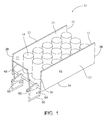
- FIG. 1 is a first perspective view of a stocking tool, in accordance with some embodiments.
- FIG. 2 is a second perspective view of a stocking tool, in accordance with some embodiments.
- FIG. 3 is a top view of a stocking tool, in accordance with some embodiments.
- FIG. 4 is a side view of a stocking tool on a shelf, in accordance with some embodiments.
- FIG. 5 is a flow diagram illustrating a method using a stocking tool, in accordance with some embodiments.
- FIG. 6 is a first perspective view of a zoning tool, in accordance with some embodiments.
- FIG. 7 is a second perspective view of the zoning tool of FIG. 6 .
- FIG. 8 is a top view of a zoning tool, in accordance with some embodiments.
- FIG. 9 is a side view of a zoning tool on a shelf, in accordance with some embodiments.
- FIG. 10A is a perspective view of a zoning tool with a moveable door in an open position, in accordance with some embodiments.
- FIG. 10B is a perspective view of a zoning tool with a moveable door in a closed position, in accordance with some embodiments.
- FIG. 11 is a side view of a zoning tool with a moveable door in a closed position and zoning product within the zoning tool, in accordance with some embodiments.
- FIG. 12 is a flow diagram illustrating a method using a zoning tool, in accordance with some embodiments.
- Stocking of shelves is an important aspect of operating a retail store, a grocery store, a warehouse and other business that require the stocking of shelves.
- the time dedicated to the stocking of shelves is valuable considering the number of persons employed by a company to do so. Further, improper stocking of shelves can result in an inefficient use of time for others as they need to move product find product or the like. Further still, shelves accessible to customers benefit from having products properly stocked and aligned on the shelves to more easily find, identify, and select desired products, including more easily identifying if a product is out of stock.
- the present inventive concepts operate to allow for easy and proper stocking of shelves with product in desired locations, occupying a predetermined or desired amount of space on the shelves, and properly aligning the product on the shelves. Further, the present inventive concepts include a tool that can be used to stock with the above benefits and then the tool may be removed for further use of stocking a different product.
- FIGS. 1-4 depict a stocking tool 10 according to embodiments of the present inventive concept.
- the stocking tool 10 may include a first adjustable rigid side member 20 , a second adjustable rigid side member 30 and a handle 40 .
- the stocking tool 10 may also include a sizing device 50 and a locking device 60 . Each of these components may be assembled to form the stocking tool 10 , in accordance with embodiments.
- the first adjustable rigid size member 20 may include a top edge 22 , a bottom edge 24 , a front edge 26 and a rear edge 28 .
- the first adjustable rigid side member 20 also includes an inner surface 21 and an outer surface 23 .
- the second adjustable rigid size member 30 may include a top edge 32 , a bottom edge 34 , a front edge 36 and a rear edge 38 .
- the second adjustable rigid side member also includes an inner surface 31 and an outer surface 33 .
- the first adjustable rigid side member 20 and the second adjustable rigid side member 30 may be operatively coupled together wherein the inner surface 21 of the first adjustable rigid side member 20 is facing the inner surface 31 of the second adjustable rigid side member 30 .
- first and second adjustable rigid side members 20 and 30 are oriented such that the top edge 22 , the bottom edge 24 , the front edge 26 and the rear edge 28 of the first adjustable rigid side member 20 are respectively aligned and substantially parallel with the top edge 32 , the bottom edge 34 , the front edge 36 and the rear edge 38 of the second adjustable rigid side member 30 .
- the bottom edge 24 of first adjustable rigid side member 20 and the bottom edge 34 of the second adjustable rigid side member 30 rest on the shelf 70 .
- the first adjustable rigid side member 20 operatively coupled to second adjustable rigid side member 30 means that the first adjustable rigid side member 20 and the second adjustable rigid side member 30 are moveable toward and away from each other to adjust a width 12 defined between the inner surface 21 of the first adjustable rigid side member 20 and the inner surface 31 of the second adjustable rigid side member 30 .
- One way that the first adjustable rigid side member 20 is operatively coupled to the second adjustable rigid side member 30 is with the sizing device 50 .
- the sizing device 50 may be coupled between the inner surface 21 and the inner surface 31 .
- the sizing device 50 may be telescoping rods to linearly adjust the width 12 between the first adjustable rigid side member 20 and the second adjustable rigid side member 30 .
- the sizing device 50 may be located such that it does not interfere with a shelf that the stocking tool 10 will be used with for stocking product 14 .
- the width 12 receives product 14 within the width between the first and second adjustable rigid side members 20 and 30 and rests on the shelf 70 and the first and second adjustable rigid side members 20 and 30 align the product within the stocking tool 10 .
- the sizing device 50 may also include a locking mechanism 52 .
- the locking mechanism 52 operated to lock the sizing device at a predetermined size to establish the width 12 between the first and second adjustable rigid side members 20 and 30 .
- the locking mechanism 52 may be a rotatable screw lock to hold the telescoping rods in a fixed position, thereby locking the width 12 at a desired measurement.
- the width 12 defined between the first and second adjustable rigid side members is maintained through the entire length and height of the first and second adjustable rigid side members 20 and 30 .
- the first and second adjustable rigid side members 20 and 30 may include a length 16 .
- the length 16 may be adjustable in order to account for different shelf depths.
- the length 16 may be adjustable in different ways.
- the first and second adjustable rigid side members 20 and 30 may each include two plates that slide next to each other to adjust the length 16
- the first and second adjustable rigid side members 20 and 30 may each include a plate nested within the original side member, wherein the nested plate may slide out of and into the original side member to adjust the length 16 of the first and second adjustable rigid side members 20 and 30 .
- the handle 40 is operatively coupled to the first adjustable rigid side member 20 and the second adjustable rigid side member 30 .
- the handle 40 is moveable between a locked position with the handle 40 activating the locking device 60 and an unlocked position with the handle 40 deactivating the locking device 60 .
- the handle 40 is rotatable.
- the handle 40 being moveable between the locked position and the unlocked position comprises the handle 40 being rotatable between the locked position with the handle 40 activating the locking device 60 to engage with the shelf 70 and the unlocked position with the handle 40 deactivating the locking device 60 to disengage from the shelf 70 .
- the locking device includes a cam 62 and a locking member 64 , wherein the handle 40 rotates about the cam axis and moves the locking member 64 to engage or disengage the shelf 70 .
- a stocking system may include a shelf 70 and a stocking tool 10 as described above. The system allows for stocking of the shelf 70 with product 10 and to locate product 14 within a defined area on the shelf 70 .
- FIG. 5 depicts a method 80 for using a stocking tool according to embodiments.
- the method 80 may include placing a stocking tool on a shelf at a desired location for a product to be stocked (Step 81 ); moving a handle of the stocking tool from an unlocked position to a locked position to lock the stocking tool in place on the shelf (Step 82 ); adjusting a width defined between first and second adjustable rigid side members, wherein the width corresponds to a size and amount of the product to be stocked on the shelf (Step 83 ); placing the product to be stocked with the tool within the width defined between the first and second adjustable rigid side members (Step 84 ); moving the handle of the stocking tool from the locked position to the unlocked position (Step 85 ); and removing the stocking tool from the shelf leaving the product on the shelf (Step 86 ).
- the method 80 may further include retaining the first and second adjustable rigid side members with a selected width defined between the first and second adjustable rigid side members. Retaining the first and second adjustable rigid side members with the selected width defined between the first and second adjustable rigid side members may comprise operating a sizing device.
- Step 84 of placing the product to be stocked with the tool may comprise placing the product on the shelf within the width defined between the first and second adjustable rigid side members.
- Step 82 of moving the handle to of the stocking tool from the unlocked position to the locked position comprises rotating the handle from a position disengaged with the shelf to a position engaged with the shelf.
- Step 85 of moving the handle to of the stocking tool from the locked position to the unlocked position comprises rotating the handle from the position engaged with the shelf to the position disengaged with the shelf.
- the method 80 may also include adjusting a length of each of the first and second adjustable rigid side members to substantially equal to a depth of the shelf.
- FIGS. 6-9 depict a zoning tool 100 according to embodiments of the present inventive concept.
- the zoning tool 100 may include a first adjustable rigid side member 120 , a second adjustable rigid side member 130 and a handle 140 .
- the zoning tool 100 may also include a sizing device 150 , a locking device 160 , and a moveable door 180 .
- Each of these components may be assembled to form the zoning tool 100 , in accordance with embodiments.
- Many of these components, such as the first adjustable rigid side member 120 , second adjustable rigid side member 130 , handle 140 , sizing device 150 , and locking device 160 may be similar to or the same as comparable components of FIGS. 1-4 , and therefore, details of these components are not repeated for brevity.
- the first adjustable rigid size member 120 may include a top edge 122 , a bottom edge 124 , a front edge 126 and a rear edge 128 .
- the first adjustable rigid side member 120 also includes an inner surface 121 and an outer surface 123 .
- the second adjustable rigid size member 130 may include a top edge 132 , a bottom edge 134 , a front edge 136 and a rear edge 138 .
- the second adjustable rigid side member also includes an inner surface 131 and an outer surface 133 .
- the first adjustable rigid side member 120 and the second adjustable rigid side member 130 may be operatively coupled together wherein the inner surface 121 of the first adjustable rigid side member 120 is facing the inner surface 131 of the second adjustable rigid side member 130 .
- first and second adjustable rigid side members 120 and 130 are oriented such that the top edge 122 , the bottom edge 124 , the front edge 126 and the rear edge 128 of the first adjustable rigid side member 120 are respectively aligned and substantially parallel with the top edge 132 , the bottom edge 134 , the front edge 136 and the rear edge 138 of the second adjustable rigid side member 130 .
- the bottom edge 124 of first adjustable rigid side member 120 and the bottom edge 134 of the second adjustable rigid side member 130 rest on a shelf 170 (see FIG. 9 ).
- the first adjustable rigid side member 120 operatively coupled to second adjustable rigid side member 130 means that the first adjustable rigid side member 120 and the second adjustable rigid side member 130 are moveable toward and away from each other to adjust a width 112 defined between the inner surface 121 of the first adjustable rigid side member 120 and the inner surface 131 of the second adjustable rigid side member 130 .
- One way that the first adjustable rigid side member 120 is operatively coupled to the second adjustable rigid side member 130 is with the sizing device 150 .
- the sizing device 150 may be coupled between the inner surface 121 and the inner surface 131 .
- the sizing device 150 may be telescoping rods to linearly adjust the width 112 between the first adjustable rigid side member 120 and the second adjustable rigid side member 130 .
- the sizing device 150 may be located such that it does not interfere with a shelf that the zoning tool 100 will be used with for stocking product 114 .
- the width 112 receives product 114 within the width between the first and second adjustable rigid side members 120 and 130 and rests on the shelf 170 and the first and second adjustable rigid side members 120 and 130 align the product within the zoning tool 100 .
- the sizing device 150 may also include a locking mechanism 152 .
- the locking mechanism 152 operated to lock the sizing device at a predetermined size to establish the width 112 between the first and second adjustable rigid side members 120 and 130 .
- the locking mechanism 152 may be a rotatable screw lock to hold the telescoping rods in a fixed position, thereby locking the width 112 at a desired measurement.
- the width 112 defined between the first and second adjustable rigid side members is maintained through the entire length and height of the first and second adjustable rigid side members 120 and 130 .
- the first and second adjustable rigid side members 120 and 130 may include a length 116 .
- the length 116 may be adjustable in order to account for different shelf depths.
- the length 116 may be adjustable in different ways.
- the first and second adjustable rigid side members 120 and 130 may each include two plates that slide next to each other to adjust the length 116
- the first and second adjustable rigid side members 120 and 130 may each include a plate nested within the original side member, wherein the nested plate may slide out of and into the original side member to adjust the length 116 of the first and second adjustable rigid side members 120 and 130 .
- the handle 140 is operatively coupled to the first adjustable rigid side member 120 and the second adjustable rigid side member 130 .
- the handle 140 is moveable between a locked position with the handle 140 activating the locking device 160 and an unlocked position with the handle 140 deactivating the locking device 160 .
- the handle 140 is rotatable.
- the handle 140 being moveable between the locked position and the unlocked position comprises the handle 140 being rotatable between the locked position with the handle 140 activating the locking device 160 to engage with the shelf 170 and the unlocked position with the handle 140 deactivating the locking device 160 to disengage from the shelf 170 .
- the locking device includes a cam 162 and a locking member 164 , wherein the handle 140 rotates about the cam axis and moves the locking member 164 to engage or disengage the shelf 170 .
- the moveable door 180 may include a first door member 181 and a second door member 182 , wherein the first door member 181 is slidably coupled to second door member 182 . This allows the moveable door 180 to adjust in width in response to adjustment of the width 12 of the zoning tool 100 .
- the moveable door is hinged on a top side, wherein the top side of the moveable door is coupled adjacent the top edge 128 of the first adjustable rigid side member 120 and adjacent the top edge 138 of the second adjustable rigid side member 130 .
- a bottom side of the moveable door 180 may be coupled on bottom corners to bottom rigid cables 184 extending operably through the first and second adjustable rigid side members 120 and 130 .
- the cables 184 extend through front edges 126 and 136 of the respective first and second adjustable rigid side members 120 and 130 . Pulling on bottom rigid cables 184 operate to rotate the moveable door into a closed position and ready to zone product within the zoning tool 10 .
- the bottom rigid cables may be pulled in response to operating the locking device 60 , wherein rotation of the handle 40 turns a gear 186 operatively engages the cables 184 to pull the cables 184 that pull from the bottom of the door 180 to move it to the closed position.
- the top side of the moveable door 180 may be operatively coupled adjacent the top edge 128 of the first adjustable rigid side member 120 and adjacent the top edge 138 of the second adjustable rigid side member 130 with a spring that biases the door 180 toward the opened position.
- the door 180 is maintained in the same position with respect to the first and second adjustable rigid side members 120 and 130 , wherein using handles 188 to pull first and second adjustable rigid side members 120 and 130 forward allows the door 180 in the closed position to move the product forward.
- a lock pin operates to keep the door 180 down on the gear 186 attached to the first and second adjustable rigid side members 120 and 130 .
- the the gear 186 is paired again, the cables 184 are released and the spring moves door 180 into the opened position.
- the zoning tool 10 may include a stop 154 coupled to the front edge 126 of the first adjustable rigid side member 120 and the front edge 136 of the second adjustable rigid side member 130 .
- the product within the zoning tool 100 is clamped between the stop 154 and moveable door 180 in response to moving the moveable door 180 linearly along the shelf as a result of the first adjustable rigid side member 120 and the second adjustable rigid side member 120 being pulled with handles 188 .
- the handle 140 operates as the stop 154 .
- a zoning system may include a shelf 170 and a zoning tool 100 as described above. The system allows for zoning of product on the shelf 170 within a defined area on the shelf 170 .
- FIG. 12 depicts a method 190 for using a zoning tool according to embodiments.
- the method 190 may include placing a zoning tool on a shelf at a desired location for zoning (Step 191 ); moving a handle of the zoning tool from an unlocked position to a locked position to lock the zoning tool in place on the shelf (Step 192 ); adjusting a width defined between first and second adjustable rigid side members, wherein the width corresponds to a size and amount of product to be zoned on the shelf (Step 193 ); locating the product to be zoned with the zoning tool within the width defined between the first and second adjustable rigid side members (Step 194 ); rotating a moveable door between an inoperable position and an operable position (Step 195 ); moving the moveable door linearly along the shelf (Step 196 ); zoning product within the zoning tool in response to moving the moveable door linearly along the shelf (Step 197 ); moving the handle of the
- the method 190 may further include retaining the first and second adjustable rigid side members apart a selected width defined between the first and second adjustable rigid side members. Retaining the first and second adjustable rigid side members with the selected width defined between the first and second adjustable rigid side members comprises operating a sizing device.
- Step 194 of locating product to be zoned within the tool comprises placing zoning tool over the product on the shelf to place product within the width defined between the first and second adjustable rigid side members.
- Step 192 of moving the handle to of the zoning tool between the unlocked position and the locked position comprises rotating the handle between a position deactivating a locking device to a position disengaged with the shelf and a position activating the locking device to a position engaged with the shelf.
- Step 197 of zoning product within the zoning tool comprises clamping product within the zoning tool between a stop of the zoning tool and the moveable door in response to moving the moveable door linearally along the shelf.
- the method 190 may also include adjusting a length of each of the first and second adjustable rigid side members to substantially equal to a depth of the shelf.
- the components defining any stocking tool may be formed of any of many different types of materials or combinations thereof that can readily be formed into shaped objects provided that the components selected are consistent with the intended operation of a stocking tool.
- the components may be formed of: rubbers (synthetic and/or natural) and/or other like materials; glasses (such as fiberglass) carbon-fiber, aramid-fiber, any combination thereof, and/or other like materials; polymers such as thermoplastics (such as ABS, Fluoropolymers, Polyacetal, Polyamide; Polycarbonate, Polyethylene, Polysulfone, and/or the like), thermosets (such as Epoxy, Phenolic Resin, Polyimide, Polyurethane, Silicone, and/or the like), any combination thereof, and/or other like materials; composites and/or other like materials; metals, such as zinc, magnesium, titanium, copper, iron, steel, carbon steel, alloy steel, tool steel, stainless steel, aluminum, any combination thereof, and/or other like
- any stocking tool may be purchased pre-manufactured or manufactured separately and then assembled together.
- any or all of the components may be manufactured simultaneously and integrally joined with one another.
- Manufacture of these components separately or simultaneously may involve extrusion, pultrusion, vacuum forming, injection molding, blow molding, resin transfer molding, casting, forging, cold rolling, milling, drilling, reaming, turning, grinding, stamping, cutting, bending, welding, soldering, hardening, riveting, punching, plating, and/or the like.
- any of the components are manufactured separately, they may then be coupled with one another in any manner, such as with adhesive, a weld, a fastener (e.g.
- Other possible steps might include sand blasting, polishing, powder coating, zinc plating, anodizing, hard anodizing, and/or painting the components for example.
Landscapes
- Engineering & Computer Science (AREA)
- Robotics (AREA)
- Mechanical Engineering (AREA)
- Workshop Equipment, Work Benches, Supports, Or Storage Means (AREA)
Abstract
Description
Claims (17)
Priority Applications (1)
| Application Number | Priority Date | Filing Date | Title |
|---|---|---|---|
| US15/841,400 US10179404B2 (en) | 2016-12-14 | 2017-12-14 | Stocking tool |
Applications Claiming Priority (3)
| Application Number | Priority Date | Filing Date | Title |
|---|---|---|---|
| US201662433979P | 2016-12-14 | 2016-12-14 | |
| US201662433984P | 2016-12-14 | 2016-12-14 | |
| US15/841,400 US10179404B2 (en) | 2016-12-14 | 2017-12-14 | Stocking tool |
Publications (2)
| Publication Number | Publication Date |
|---|---|
| US20180161977A1 US20180161977A1 (en) | 2018-06-14 |
| US10179404B2 true US10179404B2 (en) | 2019-01-15 |
Family
ID=62488170
Family Applications (1)
| Application Number | Title | Priority Date | Filing Date |
|---|---|---|---|
| US15/841,400 Active US10179404B2 (en) | 2016-12-14 | 2017-12-14 | Stocking tool |
Country Status (1)
| Country | Link |
|---|---|
| US (1) | US10179404B2 (en) |
Citations (16)
| Publication number | Priority date | Publication date | Assignee | Title |
|---|---|---|---|---|
| US747376A (en) * | 1903-06-11 | 1903-12-22 | Peter Christman | Store-goods lifter. |
| US2762647A (en) * | 1954-12-09 | 1956-09-11 | Ruth L Guest | Article grasping device |
| US4962957A (en) * | 1989-10-17 | 1990-10-16 | Arthur Traber | Pickup tool with positional locking device |
| US5469976A (en) | 1993-04-30 | 1995-11-28 | Burchell; James R. | Shelf allocation and management system |
| US5803276A (en) * | 1997-05-27 | 1998-09-08 | Vogler; Michael N. | Adjustable shelf divider |
| US6502875B1 (en) | 2001-07-25 | 2003-01-07 | Carol Berry | Device for adjusting position of shelved merchandise |
| US6719151B2 (en) | 2001-05-16 | 2004-04-13 | James Garth Close | System and method for product display, arrangement and rotation |
| US7458473B1 (en) * | 2005-12-06 | 2008-12-02 | New Dimensions Research Corporation | Display shelf |
| US20090261607A1 (en) | 2008-04-17 | 2009-10-22 | Justin Braver | Blocking tool |
| US20100108625A1 (en) * | 2008-11-03 | 2010-05-06 | Meers Ryan C | Merchandising system |
| US7992726B2 (en) | 2007-09-27 | 2011-08-09 | Shelf Advance, Inc. | Space saving manual shelf management system |
| US8727405B2 (en) * | 2011-10-17 | 2014-05-20 | Anthony L. Cameron | Merchandising grapple and method |
| US20150034576A1 (en) | 2013-08-01 | 2015-02-05 | Sap Products Ltd | Shelf Facing Systems |
| US20150208830A1 (en) * | 2014-01-24 | 2015-07-30 | Rtc Industries, Inc. | Product management display system |
| US9398817B2 (en) | 2010-12-29 | 2016-07-26 | Big Skies Limited | Apparatus for facing products |
| US20160213172A1 (en) | 2015-01-23 | 2016-07-28 | William E. Christoffersen | Shelf facing device |
-
2017
- 2017-12-14 US US15/841,400 patent/US10179404B2/en active Active
Patent Citations (16)
| Publication number | Priority date | Publication date | Assignee | Title |
|---|---|---|---|---|
| US747376A (en) * | 1903-06-11 | 1903-12-22 | Peter Christman | Store-goods lifter. |
| US2762647A (en) * | 1954-12-09 | 1956-09-11 | Ruth L Guest | Article grasping device |
| US4962957A (en) * | 1989-10-17 | 1990-10-16 | Arthur Traber | Pickup tool with positional locking device |
| US5469976A (en) | 1993-04-30 | 1995-11-28 | Burchell; James R. | Shelf allocation and management system |
| US5803276A (en) * | 1997-05-27 | 1998-09-08 | Vogler; Michael N. | Adjustable shelf divider |
| US6719151B2 (en) | 2001-05-16 | 2004-04-13 | James Garth Close | System and method for product display, arrangement and rotation |
| US6502875B1 (en) | 2001-07-25 | 2003-01-07 | Carol Berry | Device for adjusting position of shelved merchandise |
| US7458473B1 (en) * | 2005-12-06 | 2008-12-02 | New Dimensions Research Corporation | Display shelf |
| US7992726B2 (en) | 2007-09-27 | 2011-08-09 | Shelf Advance, Inc. | Space saving manual shelf management system |
| US20090261607A1 (en) | 2008-04-17 | 2009-10-22 | Justin Braver | Blocking tool |
| US20100108625A1 (en) * | 2008-11-03 | 2010-05-06 | Meers Ryan C | Merchandising system |
| US9398817B2 (en) | 2010-12-29 | 2016-07-26 | Big Skies Limited | Apparatus for facing products |
| US8727405B2 (en) * | 2011-10-17 | 2014-05-20 | Anthony L. Cameron | Merchandising grapple and method |
| US20150034576A1 (en) | 2013-08-01 | 2015-02-05 | Sap Products Ltd | Shelf Facing Systems |
| US20150208830A1 (en) * | 2014-01-24 | 2015-07-30 | Rtc Industries, Inc. | Product management display system |
| US20160213172A1 (en) | 2015-01-23 | 2016-07-28 | William E. Christoffersen | Shelf facing device |
Also Published As
| Publication number | Publication date |
|---|---|
| US20180161977A1 (en) | 2018-06-14 |
Similar Documents
| Publication | Publication Date | Title |
|---|---|---|
| US8069995B2 (en) | Adjustable tool holder | |
| EP3501757B1 (en) | Organizer with locking mechanism | |
| US9725209B1 (en) | Stackable tool box assembly | |
| US9010257B2 (en) | Locking insert mechanism and receiver to secure personal weapons, valuables and other items | |
| US8286807B2 (en) | Slidable tool holder | |
| US9457828B1 (en) | Utility cart | |
| US10001347B2 (en) | Ballistic resistant vehicle window insert | |
| DE102017125121B4 (en) | Storage device | |
| US7281338B2 (en) | Slide mounting tools, kits and systems containing same and methods related thereto | |
| EP3488733B1 (en) | Slide rail assembly and rail kit thereof | |
| EP2428332A2 (en) | Rolling container assembly with adjustable storage units | |
| US11344938B2 (en) | Paintless dent removal tool, system and method | |
| US10179404B2 (en) | Stocking tool | |
| US11827182B2 (en) | Modular tool bag | |
| US20130087982A1 (en) | Toolbox assembly | |
| EP3807167B1 (en) | Group lock box with recessed door to create a slim profile | |
| BRPI0621356A2 (en) | machine tool cartridge | |
| US9394724B2 (en) | Locking device for mounting and securing an article | |
| CN107334296A (en) | Cupboard sub-assembly with releasable support feet | |
| US10766121B2 (en) | System and method for mounting carpenter levels | |
| US20230221625A1 (en) | Attachment system for coupling a mobile computing device to optics | |
| US9307819B1 (en) | Dual opening system for a bag | |
| US9567161B2 (en) | Fastening device and system | |
| US12044058B2 (en) | System, apparatus, and method for storing material | |
| US20070144986A1 (en) | Adjustable Holder and Organizer |
Legal Events
| Date | Code | Title | Description |
|---|---|---|---|
| FEPP | Fee payment procedure |
Free format text: ENTITY STATUS SET TO UNDISCOUNTED (ORIGINAL EVENT CODE: BIG.); ENTITY STATUS OF PATENT OWNER: LARGE ENTITY |
|
| AS | Assignment |
Owner name: WAL-MART STORES, INC., ARKANSAS Free format text: ASSIGNMENT OF ASSIGNORS INTEREST;ASSIGNORS:JONES, MATTHEW ALLEN;VASGAARD, AARON JAMES;JONES, NICHOLAUS ADAM;REEL/FRAME:045100/0443 Effective date: 20161215 |
|
| AS | Assignment |
Owner name: WALMART APOLLO, LLC, ARKANSAS Free format text: ASSIGNMENT OF ASSIGNORS INTEREST;ASSIGNOR:WAL-MART STORES, INC.;REEL/FRAME:046436/0264 Effective date: 20180226 |
|
| STCF | Information on status: patent grant |
Free format text: PATENTED CASE |
|
| MAFP | Maintenance fee payment |
Free format text: PAYMENT OF MAINTENANCE FEE, 4TH YEAR, LARGE ENTITY (ORIGINAL EVENT CODE: M1551); ENTITY STATUS OF PATENT OWNER: LARGE ENTITY Year of fee payment: 4 |