US1017705A - Knitting-machine. - Google Patents
Knitting-machine. Download PDFInfo
- Publication number
- US1017705A US1017705A US57727010A US1910577270A US1017705A US 1017705 A US1017705 A US 1017705A US 57727010 A US57727010 A US 57727010A US 1910577270 A US1910577270 A US 1910577270A US 1017705 A US1017705 A US 1017705A
- Authority
- US
- United States
- Prior art keywords
- cam
- pattern
- knitting
- cylinder
- needles
- Prior art date
- Legal status (The legal status is an assumption and is not a legal conclusion. Google has not performed a legal analysis and makes no representation as to the accuracy of the status listed.)
- Expired - Lifetime
Links
Images



Classifications
-
- D—TEXTILES; PAPER
- D04—BRAIDING; LACE-MAKING; KNITTING; TRIMMINGS; NON-WOVEN FABRICS
- D04B—KNITTING
- D04B9/00—Circular knitting machines with independently-movable needles
- D04B9/42—Circular knitting machines with independently-movable needles specially adapted for producing goods of particular configuration
- D04B9/46—Circular knitting machines with independently-movable needles specially adapted for producing goods of particular configuration stockings, or portions thereof
Definitions
- My invention relates to improvements in l circular knitting machines for knitting stockings orsocks, and has for its object-the structuralsimplification of such machines, so as to render the, mechanism for carry n outthe several functions thereof certain an positive in their operation, and to minimize the liability .of the arious parts to beco ne out of'ord'er, i
- object of the invention resides in thenovel, arrangement and cooperation 0 OfJHGChaIHSIH for knitting the ,pattern and. stripe in a sock, SVlllCll'lS automatic in operationand which may be handily adjusted to vary thepattern and stripe. W'ith these. and otherob ect s 1n View, the
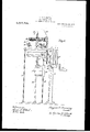
- Figure l is a side View of the com- .PlQtQQIntlCllillG;
- Fig. 2 is a frontview thereof;
- Fig. .3 is a side'view' on an enlarged "-seale-ot the cam and needle cylinders when viewed froni' the right hand side. of the 11121 chine with the gain cylinder in position "shown infFig. 2;
- Fig. 4: is 'a plan or topview of the 'iiiachine Fig.
- FIG. 5 is a detail View ofthe pattern cam actuating mechanism; Fig, ,6 a cross sectional 'yiew of the cani cylinder shou ing the. stitch cam. and ad'- Justine" block for the same; Fig]? is a, side View. of the stitch cam adjustinglilo ck; Fig.
- FIG. 8 is a cross sectional view of the can cylin-J der shou ing the elevating cam for long.
- heeledl iieedles and means for throwing sanie into and .out of operative posit-ion;
- the bed 'plate for the purpose of holding the machine more secure and against vibration, may be fastened to "ahvorkfbeneh 4, .85
- .drive pi' l1ey, 'ivhi'ch carries a 'crank'ha rdle 11, inaylie c'-o ifiiiected.ivith-any convenient chineby power; and abelt shifter 12 serves forthrowinggtlie.inachin-into and oiifl'of support a weight'or'weightsllhand is slidalily inountedfjor ⁇ '*ertical iihoveinent upon a gu de rod, 15; Yarod 16, which is hooked I at oneend' being secured :to the i 1': per .end
- the ifashionin needles are c numbere consecutively ,.in-' t e order '60- which they are thrown outof action,'upon reciprocation of the cam cylinder,
- the ma- I ,chine' is not power-driven during the fashioning-Qf'the' heeLandtoe, the operator reciprocating'the cam, cylinder by means of t 5 crank handle 11.
- cam 20 is dis-' P d s e nt h -wm 5 1 ndl l, t p:
- the tension dGXlCG comprises the lower arm 26, which is pivoted tothe cam cylinder 27, and an upper arm 28, which ispivoted at 29, the pivotal points of the two arms being-slightly out of vertical alinement, for a purpose presently explained.
- the tension device assumes either one or the other position shown in full and dotted lines, according as the rocker cam is rocked fromone position to the other, and yieldingly holds the said cam against movement. In either position the free ends of the arms are over center, and the rocker cam is rocked against the action of the tension device.
- the mode of operation in forming the heel is as follows
- the operator by means of the crank handle, causes the cam cylinder to be reciprocated, by giving the cylinder only .a partial'rotation in either direction.
- the heel of needle marked cause same to' tilt into position shown by dotted lines, and in so doing elevate the needle out of range of the knitting earns 17 and 18, the remaining needles of the series automatically raised, one more needle comes into operation after each movement, until allof the needles are again within the influence of the knitting cams, and-the grad ual widening of the web is accomplished and the heel'compl'eted.
- the cylinder is now rotated and the tubular knitting continued This completed, the-same mode of operation in thelptoe.
- the stay pin 63 engages the aperture 64 in the bed plate.
- the ratchet wheel has grooves 65 formed in its upper side and arranged at 5 tern.
- the yarn used for thepattern is also right angles to each .other, and in these used for knitting a stripe lengthwise of the grooves the leg, members of arch shaped sock.
- the tripping dogs 66 are adapted to slide.
- the cross stripes will be hereincross members of the dogs are notched on after referred to as the pattern, and the the upper and lower side respectively, as
- the yarnBQ is .within the path traveled by the friction for the body of the sock, and the pattern and roller 47, as the cam cylinder rotates," thle' st-ripeyarn' 33, is conducted from the spool roller will contact with the beveled portion 34, through the tubular guide rod 35, to the and ride over the same, thus-elevatmgthe yarnicarrier 36.
- the bar 40 20 bring the pattern cam 37 into operative poand the pattern cam connected therewith,
- a patping operation arrives, that the end of atern wheel is used which comprises a ratchet tripping dog engages a shift block 76, and 55 wheel 60, suitably mounted upon a plate'ol, shifts the" same against the tension ofthe-12 s1)I'ing75,.into position for en'gagenientbyt; the friction roller, as shown by "dotted: linesin Fig. 4.
- the stay pin 63 is passed movement of the pattern wheel, the same 12 through corresponding apertures in the plate is shifted out of operative position bythe;
- short and long heeled needles are actuated by the proper cams for continuous tubular knitting, but the long heeled needles" are actuated, so as to take the stripe yarnyonly by projecting the striper earn 80 into the cam cyllnder a sufficient distance so as to be en-' gaged thereby, butnot s'u'llicient'distance so as to engage the short heeled needles, as
- the striper cam is mounted to shift through an opening in the cam cylinder, and carries a pin 81, which extends through an aperture in the archblock 82, with an expansion coil spring 83 encircling the same, and its ends bearing against the cam and the arclr-block' R0 tatably mounted upon theend of said' pin is an adjust ng knob 84, which has an inner face of step formation, and the arch-block is provided with a lug 85, so that by pulling outwardly on the knob and giving the same a half turn, the broadest part thereof will engage the lug, and thus hold" the str-iper' cam out of operative position.
- Said stitch cam is secured to a'block .87, which is arranged to slide in the slot 88in the cam cylinder, and secured to said block by a pivot screw 89 is an ads justing head 90, having a notch 91 adapted to engage either of the pin steps 92, according as the head is in its raisedor lowered position.
- a wire spring 93 coiled at one end around the pivot 89, and extending aiound the handle 94,'serves to hold the head in engagement with the pin stops.
- the stitch cam is also shi ted into operative position when stitching the pat- 3111,, ,
- the ⁇ pattern and stripe yarn guide 36 is located directly over the striper cam, and over the upper end of the pattern cam when in an elevated position. It will be observed that, as every sixth needle, for example, has
- a pattern cani operating mechanism comprising a rotatlve wheel, radial grooves formed in the upper side thereof, archshaped trip dogsprossing each other and H161! leg niembersl engaging said grooves, and means for shifting the trlp dogs upon rotation of the wheel.
- a pattern, cam operating mechanism comprising a rotative pattern wheel, trip dogs mounted on said pattern' wheel and only, a stitch cam 86 is lowered to-feffect a" downward stroke of the needles and comslidable radially of theaxis thereof, and means cooperating with the pattern whee'l for alternately shifting the tripdogs toward and 'awayifrom the periphery of said wheel.
- the pattern earn a pattern wheel having radially shiftable trip members wheel a alternately/ah into and out of the path
- the pattern 5 In a pattern mechanism for knitting machines, the combination of the cam cylinder, a pattern cam arranged to slide thereon, a swingin arm pivoted on the cam (kylinder and having its swinging end connected with the pattern cam, a shifting bar havmg a part thereof extending beneath. said swinging arm tor actuating the latter, a
Landscapes
- Engineering & Computer Science (AREA)
- Textile Engineering (AREA)
- Knitting Machines (AREA)
- Knitting Of Fabric (AREA)
Description
A. G. TIMMING.
KNITTING MACHINE.
APPLICATION FILED AUG.15,1910.
....... I, N W
W; Z m WM 1 my? 1,017,705. Patented Feb. 20, 1912. v 'T SHEETS--SHEET .2
iygg I gasz 6. 727mm 0 mesges,
A. U. TIMMING. KNITTING MACHINE. APPLICATION IILED AUG. 15, 1910.
A. G. TIMMING,
KNITTING MACHINE. 7 APPLICATION FILED AUG-.15, 1910. 1,017,705, Patented Feh.20,1912.
7 SHEETS-SHEET 3 flu uaf CD. vrz. /jy 9w? amci,
A. O."TIMMING.
KNITTING MACHINE. APPLIOATION FILED AUG. 15, 1910.
Patented Feb, 20, 1912.
7 siIEETs-smm" 4.
A. 0 TIMMING.
- KNITTING MAOH ALP. I APPLICATION FILED Mans, 1919 1,017,705. Patented Feb;20,1912.
7 SHEETSSHEET 5.
A, O. TIEFJL'BMEJG.
KNITTING MAOBLTNP' D AUGLl APPLICATION FILE Patented @331. 20, 1912.
LMIEIUFXKWEBD 7 SHEETS-SHEET 6.
' A. TIM'MING.
KNITTING MACHINE.
APPLICATION FILED A.UG.15.193O.v
Pafiented Feb. 20, 1912.
I eA/dm .UNITED sTA'rEs PATENT OFFICE,
AUGUST 0. rnvimine, or SOUTH 3mm, INDIANA, ASSIGNOR .TO MISHAWAKA woomiiw MANUFACTURING oo., or MISHAWAKA, IENDIANA, A 0022034521011 or INDIANA.
To all whom 'it may conc etn: I
Be it known that I, Aticiis'i G. Tii iumo, a citizen of the United States, residing at South Bend, in the county of St. J osephand i State of Indiana, have invented certain new and useful Improvements in Knitting-Mm.
chines, of which the following is a specifica- I tion.
My invention relates to improvements in l circular knitting machines for knitting stockings orsocks, and has for its object-the structuralsimplification of such machines, so as to render the, mechanism for carry n outthe several functions thereof certain an positive in their operation, and to minimize the liability .of the arious parts to beco ne out of'ord'er, i
' A-further. object of the invention resides in thenovel, arrangement and cooperation 0 OfJHGChaIHSIH for knitting the ,pattern and. stripe in a sock, SVlllCll'lS automatic in operationand which may be handily adjusted to vary thepattern and stripe. W'ith these. and otherob ect s 1n View, the
invent-ion consists in certain novel features of construction, as hereinafter described and pointed out in the claims.
In the dr awings employed for illustratingj thenpreferred embodiinent of the inven- 3 tionz Figure l isa side View of the com- .PlQtQQIntlCllillG; Fig. 2 is a frontview thereof; .;Fig. .3 is a side'view' on an enlarged "-seale-ot the cam and needle cylinders when viewed froni' the right hand side. of the 11121 chine with the gain cylinder in position "shown infFig. 2; Fig. 4: is 'a plan or topview of the 'iiiachine Fig. 5 is a detail View ofthe pattern cam actuating mechanism; Fig, ,6 a cross sectional 'yiew of the cani cylinder shou ing the. stitch cam. and ad'- Justine" block for the same; Fig]? is a, side View. of the stitch cam adjustinglilo ck; Fig.
8 is a cross sectional view of the can cylin-J der shou ing the elevating cam for long.
heeledl iieedles, and means for throwing sanie into and .out of operative posit-ion;
ture of the, canrw cylindei" deuelopedbnfla lane; showing" the relative position of the 0 earns, and indicating by dot-and-dashlines the ijjat fli f cam cylinder, showing the rocker canij'for '55 automatically. and consecutivelythrowing Specification of Letters Patent.
a plane, ofthe canrpylinder, showing the.
9 isv a side view of the internal str c followed by the. needle heels for: plaiii-ti'ibular knitting; Fig. i0 is a' frag- 1 nientary View, dei'eloptid on a plane, of the Patented ream, 1912,
Application filed August 15, 1910. 'Serial No. 577,270. 7
stitching the pattern; Fig; 12 is a; 'perspec tive riewfot the pattern wheeland shifting dogs mounted thereon; Fig. 13i's a cross sectional i iewof the pattern wheel taken'on a line ofFig. 12; Fig.14 is a diagrami'n'atic 'view in which the series of small circles represent the-needles, the black solid c1relesrepresenting --'leng .i heeled andthe plain circles short heeled needles. -Fig. '15
is a detail sectional view of the shifting actuating mechanism.
Forthe purpose of clearness,-'the various steps in the operation of theinachine will icinber forming a 'par't' ofth'e pattern cam be described-inf detail and in the order' in .Which' the 'k'nit-ting'of a sock proceeds from the start to t-he'finishn The' machine embodies the -bd plate 1, I
which is supported by the standard 2, and the rod or leg 23in any. suitable manner. The bed 'plate, for the purpose of holding the machine more secure and against vibration, may be fastened to "ahvorkfbeneh 4, .85
as shown. Suitably j ni'rnaled in abea'ring 5, supported by the standard, is a'rotata'ble shaft 6, upon one end of which is mounted a loose pulley.:T-,'.and' a-drive'pulley 8-; and on its 'oppositefendis n'i'ountedav bevel gear. wheel -9," the teeth of= which mesh with; a. bevel toothed flange (not *shown) [on the lower end of the elm cylinder '10. The
.drive pi' l1ey, 'ivhi'ch carries a 'crank'ha rdle 11, inaylie c'-o ifiiiected.ivith-any convenient chineby power; and abelt shifter 12 serves forthrowinggtlie.inachin-into and oiifl'of support a weight'or'weightsllhand is slidalily inountedfjor \'*ertical iihoveinent upon a gu de rod, 15; Yarod 16, which is hooked I at oneend' being secured :to the i 1': per .end
of the frainefand its hooked 'end'a ap'te'gl to 'enga ge the n eb during" the knitting opera-Q ticn" and drawi'tlie-sgimjtailt, forthe purei .ipose ivell understood in the 'artfi fi p i sy thus far de'stiribed are iill of --.'w'ell l c nottn constructionend operation, and U0 tion during th I 40; need1esthrp4wp'ou v of. action are indicated continuous tubular lmittingQ The dot-anddash line in Fi 9, re resents the vertical Increments of t e nee le' 'heels as actuated by the cams and camgroovesin continuous tubular knitting, the needles being mounted in a stationary needle cylinder 19 The rock-cam 120,.jfor the present purpose, re mains stationary, and thus serves conjunction with' the cam 18, to depress the needles to.,efiect the stitch movement, and
2b the cam '17"elevating the needles. Thus for continuous tubular knitting the needles pass over the dropper camj21, are elevated by the cam 17 andlowered to efiect the stitch bythe cams 20 and 18, the dropper cam 22 be- 25 ing' raised bythe needles as the heels thereof passout of the cam groove, after which the needles remain in a stationary position until again actuatediin the aforesaid manner. Supposing now that the desired length of so tubular fabric fer the leg portion of the sock has been completed, an the nextlstep isvto form the heel. In forming the tubular 'fabric all'of the needles are brought into action, but. in fashioning the heel one-half so of the needles are,i'while still retaining their a stitch, raised by hand so that their heels will beabove and free ,fro n ,tlrej infiuenoe of the knitting cams, ing,, e'ntirely out of acas ionlng'oiieration. The
l-withi'n the ket A ;\in"Fi I: 14. The needlesemployedddmaking. the? eel, and which will. hereinafter be re erred to as the fashioning needles, usually consist of about one third of thetotal nuinlzier, which are equally (,i'd-iVidQd. and disposed at opposite sides of the needle .cylinder, as represented -by brackets IBj nFi 14 The ifashionin needles are c numbere consecutively ,.in-' t e order '60- which they are thrown outof action,'upon reciprocation of the cam cylinder, The ma- I ,chine'is not power-driven during the fashioning-Qf'the' heeLandtoe, the operator reciprocating'the cam, cylinder by means of t 5 crank handle 11. For the purpose of throw- ;ing the fashioning needles automatically out of'action one also. timefin order to na'rrowthe vfiat web to the extent ofone needle, at'each movement ofg-the"chmf cylinder-fas the same 59 is reci rocated', theglrockei: cam 20 is dis-' P d s e nt h -wm 5 1 ndl l, t p:
per edge, having an arc formation and; ex-
t s flawhlh engage. the notched lgmr-endsof the-last mentioned cams as the 1 same is. rocked from one the other.
- The mode of operation in forming the heel is as follows The operator, by means of the crank handle, causes the cam cylinder to be reciprocated, by giving the cylinder only .a partial'rotation in either direction. Assumin the first movement to be to the left, or 1n the direction of the arrow as shown in Fig. 10, the heel of needle marked cause same to' tilt into position shown by dotted lines, and in so doing elevate the needle out of range of the knitting earns 17 and 18, the remaining needles of the series automatically raised, one more needle comes into operation after each movement, until allof the needles are again within the influence of the knitting cams, and-the grad ual widening of the web is accomplished and the heel'compl'eted. The cylinder is now rotated and the tubular knitting continued This completed, the-same mode of operation in thelptoe.
1 g now described the mechanism and mod 5' f operation for knitting a plain sock,-
I w l nxt proceedto described the mechathe upper end of the lower arm is a plunger Na. 1 will contact with the rocker cam, and,
being deflected by said cams to make the tocompl'ete' the foot portion of the sock.-
for forming the heelis carried out for form? his hand, so that while one needle is' always nism andmode of operationfor knitting a pat-tern or cross stripe around the sock, .a double yarn feedbeing used, one for the body. ofthe sock and the other for the pat The slot 44 permits the shifting member to have an endwise movement ,Mnd a coil spring 49, one end pf which .is 'connected to the arm'40 and its opposite end to the which latter is pivoted at (12' to the bed plate of the machine, so that the pattern wheel may be'swu ng to one. side and out of operariv position,when plain knitting only is.
when moved to an inoperative-position the stay pin 63 engages the aperture 64 in the bed plate. The ratchet wheelhas grooves 65 formed in its upper side and arranged at 5 tern. The yarn used for thepattern is also right angles to each .other, and in these used for knitting a stripe lengthwise of the grooves the leg, members of arch shaped sock. For the purpose of simplifying the tripping dogs 66 are adapted to slide. The description, the cross stripes will be hereincross members of the dogs are notched on after referred to as the pattern, and the the upper and lower side respectively, as
1o lengthwise stripes simply as the stripe indicated at 67' in Fig. 12, so as to bring the The patternis formed. by bringing all of .upper sides of the dogs on a level with each the needles into action at the proper time, other. Each dog is beveled at its ends, as for example, every sixth revolution of the at 68, so that as each dog is shiftedat the cam cylinder, depending upon the space deproper time and one of their ends brought l5 siredhetween the patterns. The yarnBQ is .within the path traveled by the friction for the body of the sock, and the pattern and roller 47, as the cam cylinder rotates," thle' st-ripeyarn' 33, is conducted from the spool roller will contact with the beveled portion 34, through the tubular guide rod 35, to the and ride over the same, thus-elevatmgthe yarnicarrier 36. In order to automatically shifting member 42, and with it the bar 40 20 bring the pattern cam 37 into operative poand the pattern cam connected therewith,
sit-ion at, the proper intervals, which cam is thus bringing all of theneedles into operaarranged tosl-ide and partly projects into a tion with respect to the pattern yarn. Upon.
slanting slot 38 in the cam cylinder, the elevation of the shifting member 42, the same is pivotally connected by means of a end of the catch lever 50 engages the under 25 pivot screw 39, with the lower end of a edge thereof and holds the same elevated swinging arm 40, which in turn is pivoted until the cam cylinder has made a complete to the'cylinder at 41, the pivot member passrevolution and the pattern is stitched .ening through an elongated aperture in the t-irely around the sock, when the trippin-52; 7
V arm, so as to permit the arm to have both a on the catch lever engages the trip -.finger 3o pivotal and: longitudinal movement. The 69, and releases the attern cam-actuating ,5 arm rests upon an 'L-shaped shifting memmechanism, which thereupon assumes itsj ber 42, one arm of which has a. slot- 44, normal. position. If,jas above stated, through which a pivot screw 45 asses, and intended to stitch a pattern in the sock every its 'laterally extending arm 46 me a tricsixth revolution of the cam cylinder, a cam 55 tion roller 47 mounted on the end thereof. 70, carried by said cylinder, is arranged to,
contact with the end of a ratchet dog ftl,
which rocks on 'a pivot 72, and carries a spring actuated pawl 73 on its opposite end to engage the ratchet wheel, the ratchet dog to camcylinden tends to draw the arm down being returned to normal position aftereach 0 and' 'withit the-shifting member, when the movement by the spring 74. Upon. eaQhlatter is .not locked against movement. revolution .of the cylinder the cam/70; rocks Mounted upon the pivot screw 45, is athe ratchet. dog sufliciently -to move .thespring actuated catch lever '50, the end 51 ratchet wheel to the extent of two teeth and, 45 of'which normally rests upon the beveled the sixth movement brings the end ofone. of
upper face of-the-shifting member, and its the trip dogs 66 into the path'traveled by opposite. end carries a laterally extending the friction roller'. As the pattern wheel trip pin Before describing the operais revolved in a step by step motion, the ends 1 tionof the above mechanism for throwing of the trip dogs Contact with a plate spring 50 the pattern camjin'to and, out of operative 75, which shifts the dogs out of the path position, it isadvisable first to describe the travel of the friction roller, audit is only.-
'mcans for actuating said mechanism at the when the predetermined time for. the tripdesired intervals. F or this purpose a patping operation arrives, that the end of atern wheel is used which comprises a ratchet tripping dog engages a shift block 76, and 55 wheel 60, suitably mounted upon a plate'ol, shifts the" same against the tension ofthe-12 s1)I'ing75,.into position for en'gagenientbyt; the friction roller, as shown by "dotted: linesin Fig. 4. As the end ofthetrippingdog n passes the shifting block upon the n'extcfi 60 being done. [The stay pin 63, is passed movement of the pattern wheel, the same 12 through corresponding apertures in the plate is shifted out of operative position bythe;
' an operative or inoperative position. The pattern wheel and cooperating mechanlsm are shown in operative position in Fig. 4, and
61 and the bed plate, to retain same in either plate spring before the camcylinder again completes'a revolution. -A-'detent i l-pres;
vents reverse motion of the ]')attr n .\vliccl,
and a friction block 7 8,preferahly of leather,
is held infi contact with the-upper surface of I the pattern wheel toprevent lost motion.
The means and mode of operation for stitching a pattern will be readily'understood from the foregoing description, and I will'next proceed to describethe means a and mode of operation for stitching a stripe lengthwiseof the sock. For this purpose reference is to'be had to Figs. 8 "and 14, the
simply changing the relative positions of the Both the long and short heeled needles. short and long heeled needles" are actuated by the proper cams for continuous tubular knitting, but the long heeled needles" are actuated, so as to take the stripe yarnyonly by projecting the striper earn 80 into the cam cyllnder a sufficient distance so as to be en-' gaged thereby, butnot s'u'llicient'distance so as to engage the short heeled needles, as
plainly shown in Fig. 8. The striper cam is mounted to shift through an opening in the cam cylinder, and carries a pin 81, which extends through an aperture in the archblock 82, with an expansion coil spring 83 encircling the same, and its ends bearing against the cam and the arclr-block' R0 tatably mounted upon theend of said' pin is an adjust ng knob 84, which has an inner face of step formation, and the arch-block is provided with a lug 85, so that by pulling outwardly on the knob and giving the same a half turn, the broadest part thereof will engage the lug, and thus hold" the str-iper' cam out of operative position. Another half turn will permit the protuberance on the knob to pass beside the lug and thecam to be shifted into operative position. \Vhe'n" the striper cam is in use, the function of which is to elevatethe long 'heeled needles plete the stitch. Said stitch cam is secured to a'block .87, which is arranged to slide in the slot 88in the cam cylinder, and secured to said block by a pivot screw 89 is an ads justing head 90, having a notch 91 adapted to engage either of the pin steps 92, according as the head is in its raisedor lowered position.' A wire spring 93 coiled at one end around the pivot 89, and extending aiound the handle 94,'serves to hold the head in engagement with the pin stops. By simply giving the adjusting heada slight turn so as to disengage same from the pin stop, the
same may be raised or lowered and the stitch caln shifted into operative or ino erative position. The stitch cam is also shi ted into operative position when stitching the pat- 3111,, ,The {pattern and stripe yarn guide 36 is located directly over the striper cam, and over the upper end of the pattern cam when in an elevated position. It will be observed that, as every sixth needle, for example, has
a long heel, '"tl ey alone will be elevated'to' engage the shape yarn; which, being of a different color than the body yarn, will. stitch a stripe lengthwise of the sock, the
is bewhich cooperates with said cams, are all maintained out of operative position; the pattern wheel, which controls the actionof the pattern ca1n,being-shifted into operative position only when it is desired to form a.-
pattern or cross stripe, and the striper cam when it is desired to form astripe lengthwise of the sock;
Having thus'de'scribed my invention, what is claimed l. A pattern calnoperating mechanism,
comprising a rqtative wheel, grooves formed in the upper side thereof, trip dogs arrangedto slide in said "grooves, a shift block for contacting with the ends of the trip dogs to "shift the same in one direction, and means for shifting the trip, dogs in the opposite direction, I I
2. A pattern cani operating mechanism, comprising a rotatlve wheel, radial grooves formed in the upper side thereof, archshaped trip dogsprossing each other and H161! leg niembersl engaging said grooves, and means for shifting the trlp dogs upon rotation of the wheel.
A pattern, cam operating mechanism comprising a rotative pattern wheel, trip dogs mounted on said pattern' wheel and only, a stitch cam 86 is lowered to-feffect a" downward stroke of the needles and comslidable radially of theaxis thereof, and means cooperating with the pattern whee'l for alternately shifting the tripdogs toward and 'awayifrom the periphery of said wheel.
' 4. In a" pattern mechanism for knitting niachinea the combination with the cam cylinder and pattern. cam, actuating mecha;
nism for ,the pattern earn, a pattern wheel having radially shiftable trip members wheel a alternately/ah into and out of the path,
mp members i he actuating mechanism.
the pattern 5. In a pattern mechanism for knitting machines, the combination of the cam cylinder, a pattern cam arranged to slide thereon, a swingin arm pivoted on the cam (kylinder and having its swinging end connected with the pattern cam, a shifting bar havmg a part thereof extending beneath. said swinging arm tor actuating the latter, a
trigger mounted adjacent said shifting bar cylinder and having its swinging 01'l(l (3()11 nected with said pattern cam, alshi fting bar having a longitudinal slot and a lateral extension extending beneath said swinging arm for actuating the latter, a pivot member on the cam cylinder extending through the slot in the shifting bar, a rigger mount- .ed on said pivot member adj aeentthe shifting arm and adapted for locking engagem nt with the lateral extension of the shifta mg bar when 111 an elevated pos1t1on, means" fortripping saidv trigger, and mechanism for actuating the shifting bar at predetermined periods.
In testimony whereof I aflix my signature,
two Witnesses. AUGUST C. TIMMING. lVitnesses CHARLES G. HAGERTY GEORGE W. Slums.
in presence of
Priority Applications (1)
| Application Number | Priority Date | Filing Date | Title |
|---|---|---|---|
| US57727010A US1017705A (en) | 1910-08-15 | 1910-08-15 | Knitting-machine. |
Applications Claiming Priority (1)
| Application Number | Priority Date | Filing Date | Title |
|---|---|---|---|
| US57727010A US1017705A (en) | 1910-08-15 | 1910-08-15 | Knitting-machine. |
Publications (1)
| Publication Number | Publication Date |
|---|---|
| US1017705A true US1017705A (en) | 1912-02-20 |
Family
ID=3086007
Family Applications (1)
| Application Number | Title | Priority Date | Filing Date |
|---|---|---|---|
| US57727010A Expired - Lifetime US1017705A (en) | 1910-08-15 | 1910-08-15 | Knitting-machine. |
Country Status (1)
| Country | Link |
|---|---|
| US (1) | US1017705A (en) |
Cited By (1)
| Publication number | Priority date | Publication date | Assignee | Title |
|---|---|---|---|---|
| US2743595A (en) * | 1955-02-02 | 1956-05-01 | Jacquard Knitting Machine Comp | Cam means for knitting machines |
-
1910
- 1910-08-15 US US57727010A patent/US1017705A/en not_active Expired - Lifetime
Cited By (1)
| Publication number | Priority date | Publication date | Assignee | Title |
|---|---|---|---|---|
| US2743595A (en) * | 1955-02-02 | 1956-05-01 | Jacquard Knitting Machine Comp | Cam means for knitting machines |
Similar Documents
| Publication | Publication Date | Title |
|---|---|---|
| US1017705A (en) | Knitting-machine. | |
| US3469422A (en) | Knitting machine size changer | |
| US1782007A (en) | Knitting machine | |
| US1929125A (en) | Knitting machine attachment | |
| US629503A (en) | Knitting-machine. | |
| US486767A (en) | clarke | |
| US188441A (en) | Improvement in knitting-machines | |
| US2143198A (en) | Knitting machine and method of knitting | |
| US480043A (en) | sedmihradsky | |
| US497118A (en) | Half to joseph clifford moore | |
| US488575A (en) | Knitting-machine | |
| US3395593A (en) | Mechanism for selecting patterns in an automatic pattern stitch sewing machine | |
| US678883A (en) | Knitting-machine. | |
| US537802A (en) | Island | |
| US391832A (en) | Chaeles james | |
| US333102A (en) | Knitting-machine | |
| US250505A (en) | Knitting-machine | |
| US324796A (en) | Knitting-machine | |
| US471220A (en) | Circular-knitting machine | |
| US1710027A (en) | Knitting machine | |
| US309761A (en) | byfield | |
| US596299A (en) | Knitting-machine | |
| US55420A (en) | Improvement in knitting-machines | |
| US220924A (en) | Improvement in knitting-machines | |
| US932578A (en) | Knitting-machine. |