US1017527A - Electric-line switch. - Google Patents
Electric-line switch. Download PDFInfo
- Publication number
- US1017527A US1017527A US53086009A US1909530860A US1017527A US 1017527 A US1017527 A US 1017527A US 53086009 A US53086009 A US 53086009A US 1909530860 A US1909530860 A US 1909530860A US 1017527 A US1017527 A US 1017527A
- Authority
- US
- United States
- Prior art keywords
- members
- arm
- contacts
- frame
- electric
- Prior art date
- Legal status (The legal status is an assumption and is not a legal conclusion. Google has not performed a legal analysis and makes no representation as to the accuracy of the status listed.)
- Expired - Lifetime
Links
- 239000012212 insulator Substances 0.000 description 8
- 238000010276 construction Methods 0.000 description 5
- 239000000543 intermediate Substances 0.000 description 5
- 230000000994 depressogenic effect Effects 0.000 description 4
- 230000000630 rising effect Effects 0.000 description 4
- 239000004020 conductor Substances 0.000 description 3
- 239000000463 material Substances 0.000 description 3
- 230000008878 coupling Effects 0.000 description 2
- 238000010168 coupling process Methods 0.000 description 2
- 238000005859 coupling reaction Methods 0.000 description 2
- 239000011810 insulating material Substances 0.000 description 2
- RYGMFSIKBFXOCR-UHFFFAOYSA-N Copper Chemical class [Cu] RYGMFSIKBFXOCR-UHFFFAOYSA-N 0.000 description 1
- 230000004048 modification Effects 0.000 description 1
- 238000012986 modification Methods 0.000 description 1
Images


Classifications
-
- H—ELECTRICITY
- H01—ELECTRIC ELEMENTS
- H01H—ELECTRIC SWITCHES; RELAYS; SELECTORS; EMERGENCY PROTECTIVE DEVICES
- H01H31/00—Air-break switches for high tension without arc-extinguishing or arc-preventing means
- H01H31/26—Air-break switches for high tension without arc-extinguishing or arc-preventing means with movable contact that remains electrically connected to one line in open position of switch
- H01H31/28—Air-break switches for high tension without arc-extinguishing or arc-preventing means with movable contact that remains electrically connected to one line in open position of switch with angularly-movable contact
Definitions
- the arm members 36 are depressed at one point as shown at 41 and pivotally connected to the arm at this depressed point is a clamp device formed of reversely curving bands 42-4t3 fitting in annular channels in insulating devices 45 supported upon upright members one of which is represented at 46.
- Each of the band members 42 is rovided with an u wardly directed stan ard 47 while each 0? the band members 43 is provided with a similar standard 48, the standards extending upon opposite sides of the dc ressed portion 4:]. of the arm 36 and secure thereto by a transverse bolt 49L
- the vertical members 46 are pivotally coupled to the arms 36 and insulated therefrom.
- the improved device may be applied at any desired point in the circuit and is simple in construction, ca be inexpensively manufactured and app ied, and adapted without material structural changes to line wires of different kinds and to line wires employed for different purposes.
- two of the intermediate transverse members are members are the insulator devices 18-49 with the arms 36 coupled thereto in the same manner as shown in Figs. 1 and 2.
- the terminal transverse members 11-12 are provided respectively with the insulator members 14- 15 and 16-17 and each provided with s ring contacts 25-26 and 30-31, the only lfierence bein that the contacts are both directed upwar y instead of one upwardly and one downwardly as shown in the sin le structure.
- the frame 10 in the rloul lc structure is likewise provided with a central intermediate transverse member 61 carrying insulator members 6263, and each of the insulator members is provided respectively with cncirclin clamp members 64-65 constituting com uctors and.
- the improved device is simple in construction, can be applied without material structural changes to line wires of various forms and to line wires employed for various purposes.
Landscapes
- Connections Arranged To Contact A Plurality Of Conductors (AREA)
Description
P. FISHER.
ELECTRIC LINE SWITCH.
APPLIHATION FILED D1201, 1009.
Patented Feb. 13, 1912.
BSHBETB-SHEET 1 Qwuwwboz fill/2' 129/161" P. FISHER.
ELECTRIC LINE swma. APPLICATION FILED DEO.1,1909.
Patented Feb. 13, 1912.
3 SHEETS-SHEET 3 WiHII.
FRANK FISHER, F REARDAN, WASHINGTON.
ELECTRIC-LINE SWITCH.
Specification of Letters Patent.
Patented Feb. 13. 1912.
Application filed December 1, 1909. Serial No. 530,860.
To all whom it may concern:
Be it known that I, FRANK Fisnun, a citizen of the United States, residing at Beardan, in the county of Lincoln, State of Washington, have invented certain new and useful Improvements in Electric-Line Switches; and I do hereby declare the following to be a full, clear, and exact description of the invention, such "as will enable others skilled in the art to which it appertains to make and use the same.
.This invention relates to improvements in electric switches which may be employed in connectionwith various electrical appliances such as trolley lines, conductor wires whereby electrical power is transmitted from place to place, and the like, and has for one of its objects to simplify and improve the construction and increase the efliciency and utility of devices of this character.
Another object of the invention is to provide a simply constructed device which may be arranged at any convenient point, and which may be applied to single or double lines without material structural changes in the parts and applicable more particularly to high tension circuits.
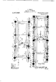
With these and other objects in view, the invention consists in certain nrwel features of construction as hereinafter shown and described and then specifically pointed out in the claims; and, in the drawings illustrative of the preferred embodiment of the invention, Figure 1 is a side elevation of the improved device arranged in connection with a single line. Fig. 2 is a plan view of the parts shown in Fig. 1. Fig. 3 is a side elevation of the improved device arranged in connection with a double line. Fig. 4 is a plan view of the parts shown in Fig. 3.
The improved device may be located at any convenient point, and is generally supported upon a suitable frame work, and this rame work may be of any required size or of any suitable construction, but. for the purpose of illustration :1 conventional supportmg frame is represented at 10, and includes a plurality of transverse supporting members 11-42 located at the ends of the frame and an intermediate transverse member 13. Rising from the end member 11 are two supports or standards 1j415, while similar supports or standards 16-17 and 18-19 are supported respectively upon the transverse members 12 and 13. The members are constructed of suitable insulating material and upturned at their opposite ends and tact members 3839, as shown.
each is provided with an encircling bearing channel near its upper end to support suitable clamping devices, and as the clamping devices which are carried by the members 1et-15 are precisely alike, like reference characters are employed for both. The clamping devices above noted comprise reycrsely curving bands 20- 21 bearing with- 1n the-channels of the members l4- and coupled at their terminals by ti'ansverse bolts E22-23, the main line wires, represented at 24 being coupled by the bolt 22 between the members and 21 at one end, while spring contact plates 2526 are coupled thereto by bolts 23, the plates 25-26 being directed upwardly, as shown. Similar clamping devices are carried by the members 1617 and each consists of curved clamp members 2728 supporting the line wires 24 by then; atone end by a bolt 29 and supporting downwardly directed spring contacts 30-3l by clamp bolts 32 at their op,-
posite ends, as shown. The members 18-19 are also provided with clamping devices comprising curved plates 3334 and connected togethtr at one end by a bolt 35 and pivotally supportlng an arm 36 by a bolt 37. The arm 36 is preferably formed of two portions placed side by side, and between the arm portions at one end is secured a contact plate 38'adaptcd to engage between the spring contacts 2526, and with a similar contact plate 39 secured between the arm portions at the opposite end and operating between the contact plates 303l. A conductor wire 40 is connected at its ends to each of the con- By this arrangement it will be obvious that when the arm 36 is so arranged that the contact members 3839 are in electrical connection with the contacts 2526 and EEO-31 the current will be continuous between the two portions of the line wires 24s If, however, the arm 36 be tilted upon its pivot 37 the circuit will be broken by disengaging the plates 3839 from the spring contacts, and one feature of the improved device is the means whereby this movement of the arm 36 is accomplished and this mechanism will now be described.
The arm members 36 are depressed at one point as shown at 41 and pivotally connected to the arm at this depressed point is a clamp device formed of reversely curving bands 42-4t3 fitting in annular channels in insulating devices 45 supported upon upright members one of which is represented at 46. Each of the band members 42 is rovided with an u wardly directed stan ard 47 while each 0? the band members 43 is provided with a similar standard 48, the standards extending upon opposite sides of the dc ressed portion 4:]. of the arm 36 and secure thereto by a transverse bolt 49L By this means the vertical members 46 are pivotally coupled to the arms 36 and insulated therefrom. Rising from the lower portion of the frame work 1.0 are two standards 50-5], and pivoted at 52--53 to these standards is a yoke member 54 with a lever arm .35 extending centrally from the-yoke frame. By this means it will be obvious that the vertical movement of the lever 55 will produce corresponding vertical movement of the upright members 46 and thus actuate the arms 36. Rising from the frame work 10 adjacent to the lever arm 55 is a curved guide member 56 having transverse apertures 5758, while the lever arm 55 is provided with a transverse aperture adapted to alternately register with the apertures 57-58. The a erture 57 is so located that the aperture 0 the lever arm will register therewith when the arm 36 is in its operative position, or with the contacts 38-39 in" engagement with their respective contacts, as shown in Fi 1, and if it is desired to lock the arm in its closed position, a bolt or other suitable locking devicewnay be insorted through the registering apertures. The other aperture 58 will be so located that it will register with the aperture in the lever arm when the latter is in its depressed position, and hold the arm 36 with its contact members disconnected from the spring contacts, and the lever arm may be locked in 0 en position if preferred by a locking mem er passing through the aperture 58.
The improved device may be applied at any desired point in the circuit and is simple in construction, ca be inexpensively manufactured and app ied, and adapted without material structural changes to line wires of different kinds and to line wires employed for different purposes.
In 3 and ei the improved apparatus arranged for use in connection ovith LWO or more lines, and is substantially the same except that two of the arms are; employed arranged end to end and. a single operating means arranged to simultaneously actuate both arms. As many of the parts employed in the modified or double structure are the same as those em plcyed in the single structure illustrated in Figs. 1 and 2, like reference characters are employed for like parts in each.
In the double or mo lified structure two of the intermediate transverse members are members are the insulator devices 18-49 with the arms 36 coupled thereto in the same manner as shown in Figs. 1 and 2. The terminal transverse members 11-12 are provided respectively with the insulator members 14- 15 and 16-17 and each provided with s ring contacts 25-26 and 30-31, the only lfierence bein that the contacts are both directed upwar y instead of one upwardly and one downwardly as shown in the sin le structure. The frame 10 in the rloul lc structure is likewise provided with a central intermediate transverse member 61 carrying insulator members 6263, and each of the insulator members is provided respectively with cncirclin clamp members 64-65 constituting com uctors and. carrying spring cont-acts 66--67 at two opposite, sides. The arms 36 are provided at their outer ends with the contact plates 3839 in the same Figs. 1 and 2, and at theirinner'ends the arms 36 are provided with contacts 69- 70 engaging respectively with the spring contacts 66--67. The aims 36 are provided with the depressed portions 41 as in the structures shown in Figs. I'and 2 and pivoted at 37 to the insulator menibers 19. in the same manner as in the structureshown in Figs.1and2,as shown. Located beneath the transverse members 61 and likewise beneath the insulator members 655-63 are two other insulator members one of which is shown at 71 and provided with a clamp device 72 and including a longitudinally extending bar 73, the bar being coupled at its ends by links to the lever arms 36,- one pair of the links being representedat 7 i-75. willbe understood that each pair of the arms 36 is provided with one of the.insulatcr members 71, the bars 73 and a 'pair of the links 74-75, but one pair only of the links and bars are shown. The insulator members 71 are each connected to a vertical mem her, one of=which is shown at 7 6,andtheitwo vertical members are coupled by a transversely extending yoke frame 77, and rising from the frame work 10 are spaced standards 7 8--7 9 pivoted at -81 to the yoke frame. The yoke frame is provided with an intermediate lever arm 82 by means of which the yoke frame is actuated and the members 76, 71, 73 and 74-75 actuated to operate the arms 36, as will be obvious. The lever arm 82 operates through a curved guide member 83 having spaced transverse apertures S t -85 which register with a corresponding apercn'iployed and indicated by the characters 59 60, and connected to these transverse nor as the similar mechanism illustrated in Figs. 1 and 2.
ture in the lever arm 82 to receive a locking It will be noted that the pivots 37 are located nearer to the contacts 31-32 than to the contacts 252(3 in Figs. 1 and 2 and nearer to the contacts 2526 than to the contacts (ESL-7O in the modification shown in Figs. 3 and 4, so that the arms 36 will be released from their respective contacts at an earlier period at one end than at the other, so that the are will be broken first on one side. In the modified or double pole structure illustrated in Fig. 3 the links Ti -T5 may be provided with guides 8(i87 if found necessary.
The improved device is simple in construction, can be applied without material structural changes to line wires of various forms and to line wires employed for various purposes.
What is claimed is I 1. Inadevice of the class described, a supporting frame, a plurality of standards of insulating material spaced apart and arranged in pairs, said pairs being located at the terminals of the frame and at interme diate points thereon, clamp devices carried by said terminal standards, line wires coupled to said terminal clamp devices at one end, electric contacts carried by said terminal clamp devices at. the opposite ends, two arms pivoted at opposite sides of said frame and in alinement with said terminal standards, electric contacts carried by said arms and engaging respectively with the contacts of said standards, a lever arm mounted in said frame, a segment carried by said frame and over which said lever arm operates, connecting means between said lever arm and said contact carrying arm, and means for coupling said lever to said segment.
2. In a device of the class described, a supporting frame, line wires connected to said frame and each provided with an electric contact, an arm mounted to swing upon said frame and provided with electric contacts at its ends adapted to be engaged with and disengaged from the contacts of said line wires, a conductor element between the contacts of said swinging arm, a standard carried by said frame, a lever arm swinging from said standard, a segment carried by said frame and over which said lever arm operates, connecting means between said lever arm and said swinging contact carrying arm, and means for coupling said lever arm to said segment.
In testimony whereof, I aifix my signature, in presence of two witnesses.
FRANK FISHER.
\Vitnesses:
C. H. Fmnow, Josnrn GUTH.
Priority Applications (1)
| Application Number | Priority Date | Filing Date | Title |
|---|---|---|---|
| US53086009A US1017527A (en) | 1909-12-01 | 1909-12-01 | Electric-line switch. |
Applications Claiming Priority (1)
| Application Number | Priority Date | Filing Date | Title |
|---|---|---|---|
| US53086009A US1017527A (en) | 1909-12-01 | 1909-12-01 | Electric-line switch. |
Publications (1)
| Publication Number | Publication Date |
|---|---|
| US1017527A true US1017527A (en) | 1912-02-13 |
Family
ID=3085829
Family Applications (1)
| Application Number | Title | Priority Date | Filing Date |
|---|---|---|---|
| US53086009A Expired - Lifetime US1017527A (en) | 1909-12-01 | 1909-12-01 | Electric-line switch. |
Country Status (1)
| Country | Link |
|---|---|
| US (1) | US1017527A (en) |
-
1909
- 1909-12-01 US US53086009A patent/US1017527A/en not_active Expired - Lifetime
Similar Documents
| Publication | Publication Date | Title |
|---|---|---|
| US819360A (en) | Electrical switch. | |
| US1017527A (en) | Electric-line switch. | |
| US964536A (en) | Electric switch. | |
| US500423A (en) | Double-pole switch | |
| US925994A (en) | Oil-switch. | |
| US1748752A (en) | Electric switch | |
| US502300A (en) | Electric-pole changer | |
| US1319307A (en) | Planoqrapm co | |
| US2174236A (en) | Multiple-blade disconnecting switch | |
| US3164694A (en) | Double break high voltage disconnect switch | |
| US499646A (en) | Switch | |
| US1685934A (en) | Circuit breaker | |
| US239723A (en) | Telegraph-key | |
| US1949164A (en) | High tension switch | |
| US110970A (en) | Improvement in mechanisms for opening and closing telegraphic station-circuits | |
| US2065165A (en) | High tension disconnecting switch | |
| US446623A (en) | Electric switch | |
| US525936A (en) | Electric switch | |
| US480475A (en) | Telegraph-key | |
| US1094693A (en) | Oil-switch. | |
| US524383A (en) | Bus-bar switch for central stations | |
| US2431147A (en) | Switch construction | |
| US1404609A (en) | Transmission switch | |
| US732253A (en) | Circuit-breaker. | |
| US1005402A (en) | Electric switch. |