US10174697B2 - Fuel supply device for LPDI engine and start control method of LPDI engine having the fuel supply device - Google Patents
Fuel supply device for LPDI engine and start control method of LPDI engine having the fuel supply device Download PDFInfo
- Publication number
- US10174697B2 US10174697B2 US15/610,257 US201715610257A US10174697B2 US 10174697 B2 US10174697 B2 US 10174697B2 US 201715610257 A US201715610257 A US 201715610257A US 10174697 B2 US10174697 B2 US 10174697B2
- Authority
- US
- United States
- Prior art keywords
- pressure
- fuel
- line
- low pressure
- engine
- Prior art date
- Legal status (The legal status is an assumption and is not a legal conclusion. Google has not performed a legal analysis and makes no representation as to the accuracy of the status listed.)
- Active
Links
Images


Classifications
-
- F—MECHANICAL ENGINEERING; LIGHTING; HEATING; WEAPONS; BLASTING
- F02—COMBUSTION ENGINES; HOT-GAS OR COMBUSTION-PRODUCT ENGINE PLANTS
- F02M—SUPPLYING COMBUSTION ENGINES IN GENERAL WITH COMBUSTIBLE MIXTURES OR CONSTITUENTS THEREOF
- F02M21/00—Apparatus for supplying engines with non-liquid fuels, e.g. gaseous fuels stored in liquid form
- F02M21/02—Apparatus for supplying engines with non-liquid fuels, e.g. gaseous fuels stored in liquid form for gaseous fuels
- F02M21/0203—Apparatus for supplying engines with non-liquid fuels, e.g. gaseous fuels stored in liquid form for gaseous fuels characterised by the type of gaseous fuel
- F02M21/0209—Hydrocarbon fuels, e.g. methane or acetylene
- F02M21/0212—Hydrocarbon fuels, e.g. methane or acetylene comprising at least 3 C-Atoms, e.g. liquefied petroleum gas [LPG], propane or butane
-
- F—MECHANICAL ENGINEERING; LIGHTING; HEATING; WEAPONS; BLASTING
- F02—COMBUSTION ENGINES; HOT-GAS OR COMBUSTION-PRODUCT ENGINE PLANTS
- F02D—CONTROLLING COMBUSTION ENGINES
- F02D41/00—Electrical control of supply of combustible mixture or its constituents
- F02D41/02—Circuit arrangements for generating control signals
- F02D41/04—Introducing corrections for particular operating conditions
- F02D41/06—Introducing corrections for particular operating conditions for engine starting or warming up
- F02D41/062—Introducing corrections for particular operating conditions for engine starting or warming up for starting
-
- F—MECHANICAL ENGINEERING; LIGHTING; HEATING; WEAPONS; BLASTING
- F02—COMBUSTION ENGINES; HOT-GAS OR COMBUSTION-PRODUCT ENGINE PLANTS
- F02D—CONTROLLING COMBUSTION ENGINES
- F02D19/00—Controlling engines characterised by their use of non-liquid fuels, pluralities of fuels, or non-fuel substances added to the combustible mixtures
- F02D19/02—Controlling engines characterised by their use of non-liquid fuels, pluralities of fuels, or non-fuel substances added to the combustible mixtures peculiar to engines working with gaseous fuels
- F02D19/021—Control of components of the fuel supply system
-
- F—MECHANICAL ENGINEERING; LIGHTING; HEATING; WEAPONS; BLASTING
- F02—COMBUSTION ENGINES; HOT-GAS OR COMBUSTION-PRODUCT ENGINE PLANTS
- F02D—CONTROLLING COMBUSTION ENGINES
- F02D41/00—Electrical control of supply of combustible mixture or its constituents
- F02D41/0025—Controlling engines characterised by use of non-liquid fuels, pluralities of fuels, or non-fuel substances added to the combustible mixtures
- F02D41/0027—Controlling engines characterised by use of non-liquid fuels, pluralities of fuels, or non-fuel substances added to the combustible mixtures the fuel being gaseous
-
- F—MECHANICAL ENGINEERING; LIGHTING; HEATING; WEAPONS; BLASTING
- F02—COMBUSTION ENGINES; HOT-GAS OR COMBUSTION-PRODUCT ENGINE PLANTS
- F02D—CONTROLLING COMBUSTION ENGINES
- F02D41/00—Electrical control of supply of combustible mixture or its constituents
- F02D41/30—Controlling fuel injection
- F02D41/3082—Control of electrical fuel pumps
-
- F—MECHANICAL ENGINEERING; LIGHTING; HEATING; WEAPONS; BLASTING
- F02—COMBUSTION ENGINES; HOT-GAS OR COMBUSTION-PRODUCT ENGINE PLANTS
- F02D—CONTROLLING COMBUSTION ENGINES
- F02D41/00—Electrical control of supply of combustible mixture or its constituents
- F02D41/30—Controlling fuel injection
- F02D41/38—Controlling fuel injection of the high pressure type
- F02D41/3809—Common rail control systems
- F02D41/3836—Controlling the fuel pressure
- F02D41/3845—Controlling the fuel pressure by controlling the flow into the common rail, e.g. the amount of fuel pumped
- F02D41/3854—Controlling the fuel pressure by controlling the flow into the common rail, e.g. the amount of fuel pumped with elements in the low pressure part, e.g. low pressure pump
-
- F—MECHANICAL ENGINEERING; LIGHTING; HEATING; WEAPONS; BLASTING
- F02—COMBUSTION ENGINES; HOT-GAS OR COMBUSTION-PRODUCT ENGINE PLANTS
- F02M—SUPPLYING COMBUSTION ENGINES IN GENERAL WITH COMBUSTIBLE MIXTURES OR CONSTITUENTS THEREOF
- F02M21/00—Apparatus for supplying engines with non-liquid fuels, e.g. gaseous fuels stored in liquid form
- F02M21/02—Apparatus for supplying engines with non-liquid fuels, e.g. gaseous fuels stored in liquid form for gaseous fuels
- F02M21/0218—Details on the gaseous fuel supply system, e.g. tanks, valves, pipes, pumps, rails, injectors or mixers
- F02M21/0221—Fuel storage reservoirs, e.g. cryogenic tanks
-
- F—MECHANICAL ENGINEERING; LIGHTING; HEATING; WEAPONS; BLASTING
- F02—COMBUSTION ENGINES; HOT-GAS OR COMBUSTION-PRODUCT ENGINE PLANTS
- F02M—SUPPLYING COMBUSTION ENGINES IN GENERAL WITH COMBUSTIBLE MIXTURES OR CONSTITUENTS THEREOF
- F02M21/00—Apparatus for supplying engines with non-liquid fuels, e.g. gaseous fuels stored in liquid form
- F02M21/02—Apparatus for supplying engines with non-liquid fuels, e.g. gaseous fuels stored in liquid form for gaseous fuels
- F02M21/0218—Details on the gaseous fuel supply system, e.g. tanks, valves, pipes, pumps, rails, injectors or mixers
- F02M21/023—Valves; Pressure or flow regulators in the fuel supply or return system
- F02M21/0239—Pressure or flow regulators therefor
-
- F—MECHANICAL ENGINEERING; LIGHTING; HEATING; WEAPONS; BLASTING
- F02—COMBUSTION ENGINES; HOT-GAS OR COMBUSTION-PRODUCT ENGINE PLANTS
- F02M—SUPPLYING COMBUSTION ENGINES IN GENERAL WITH COMBUSTIBLE MIXTURES OR CONSTITUENTS THEREOF
- F02M21/00—Apparatus for supplying engines with non-liquid fuels, e.g. gaseous fuels stored in liquid form
- F02M21/02—Apparatus for supplying engines with non-liquid fuels, e.g. gaseous fuels stored in liquid form for gaseous fuels
- F02M21/0218—Details on the gaseous fuel supply system, e.g. tanks, valves, pipes, pumps, rails, injectors or mixers
- F02M21/0245—High pressure fuel supply systems; Rails; Pumps; Arrangement of valves
-
- F—MECHANICAL ENGINEERING; LIGHTING; HEATING; WEAPONS; BLASTING
- F02—COMBUSTION ENGINES; HOT-GAS OR COMBUSTION-PRODUCT ENGINE PLANTS
- F02M—SUPPLYING COMBUSTION ENGINES IN GENERAL WITH COMBUSTIBLE MIXTURES OR CONSTITUENTS THEREOF
- F02M37/00—Apparatus or systems for feeding liquid fuel from storage containers to carburettors or fuel-injection apparatus; Arrangements for purifying liquid fuel specially adapted for, or arranged on, internal-combustion engines
- F02M37/0011—Constructional details; Manufacturing or assembly of elements of fuel systems; Materials therefor
- F02M37/0023—Valves in the fuel supply and return system
-
- F—MECHANICAL ENGINEERING; LIGHTING; HEATING; WEAPONS; BLASTING
- F02—COMBUSTION ENGINES; HOT-GAS OR COMBUSTION-PRODUCT ENGINE PLANTS
- F02M—SUPPLYING COMBUSTION ENGINES IN GENERAL WITH COMBUSTIBLE MIXTURES OR CONSTITUENTS THEREOF
- F02M37/00—Apparatus or systems for feeding liquid fuel from storage containers to carburettors or fuel-injection apparatus; Arrangements for purifying liquid fuel specially adapted for, or arranged on, internal-combustion engines
- F02M37/0047—Layout or arrangement of systems for feeding fuel
- F02M37/0052—Details on the fuel return circuit; Arrangement of pressure regulators
-
- F—MECHANICAL ENGINEERING; LIGHTING; HEATING; WEAPONS; BLASTING
- F02—COMBUSTION ENGINES; HOT-GAS OR COMBUSTION-PRODUCT ENGINE PLANTS
- F02D—CONTROLLING COMBUSTION ENGINES
- F02D41/00—Electrical control of supply of combustible mixture or its constituents
- F02D41/30—Controlling fuel injection
- F02D41/38—Controlling fuel injection of the high pressure type
- F02D2041/389—Controlling fuel injection of the high pressure type for injecting directly into the cylinder
-
- F—MECHANICAL ENGINEERING; LIGHTING; HEATING; WEAPONS; BLASTING
- F02—COMBUSTION ENGINES; HOT-GAS OR COMBUSTION-PRODUCT ENGINE PLANTS
- F02D—CONTROLLING COMBUSTION ENGINES
- F02D2200/00—Input parameters for engine control
- F02D2200/02—Input parameters for engine control the parameters being related to the engine
- F02D2200/06—Fuel or fuel supply system parameters
- F02D2200/0602—Fuel pressure
-
- F—MECHANICAL ENGINEERING; LIGHTING; HEATING; WEAPONS; BLASTING
- F02—COMBUSTION ENGINES; HOT-GAS OR COMBUSTION-PRODUCT ENGINE PLANTS
- F02D—CONTROLLING COMBUSTION ENGINES
- F02D2200/00—Input parameters for engine control
- F02D2200/02—Input parameters for engine control the parameters being related to the engine
- F02D2200/06—Fuel or fuel supply system parameters
- F02D2200/0606—Fuel temperature
-
- Y—GENERAL TAGGING OF NEW TECHNOLOGICAL DEVELOPMENTS; GENERAL TAGGING OF CROSS-SECTIONAL TECHNOLOGIES SPANNING OVER SEVERAL SECTIONS OF THE IPC; TECHNICAL SUBJECTS COVERED BY FORMER USPC CROSS-REFERENCE ART COLLECTIONS [XRACs] AND DIGESTS
- Y02—TECHNOLOGIES OR APPLICATIONS FOR MITIGATION OR ADAPTATION AGAINST CLIMATE CHANGE
- Y02T—CLIMATE CHANGE MITIGATION TECHNOLOGIES RELATED TO TRANSPORTATION
- Y02T10/00—Road transport of goods or passengers
- Y02T10/10—Internal combustion engine [ICE] based vehicles
- Y02T10/30—Use of alternative fuels, e.g. biofuels
Definitions
- the present invention generally relates to a fuel supply device for a liquefied petroleum direct injection (LPDI) engine in which liquefied petroleum gas (LPG) is directly injected into a combustion chamber and a start control method of an LPDI engine having the fuel supply device.
- LPDI liquefied petroleum direct injection
- a conventional liquefied petroleum injection (LPI) engine is configured to inject liquefied petroleum gas (LPG) supplied from a fuel tank into an intake port thereof without gasifying LPG through a mixer, so that LPG burns in a combustion chamber.
- LPG liquefied petroleum gas
- an LPDI engine is configured to inject LPG supplied from a fuel tank directly into a combustion chamber instead of into an intake port thereof by compressing LPG to a high pressure.
- the LPDI engine requires a fuel supply technology enabling fuel supplied from the fuel tank to be compressed to a high pressure before being injected directly into the combustion chamber.
- Various aspects of the present invention are directed to providing a fuel supply device for a liquefied petroleum direct injection (LPDI) engine in which liquefied petroleum gas (LPG) is directly injected into a combustion chamber and a start control method of an LPDI engine having the above-described fuel supply device, the fuel supply device being able to prevent a delay in starting due to a phenomenon including vapor locking, and obtain a suitable level of starting ability during the start of the engine.
- LPDI liquefied petroleum direct injection
- a fuel supply device for an LPDI engine may include: a high pressure fuel pump receiving fuel supplied through a supply line from a fuel tank and compressing fuel to a pressure higher than a pressure at which fuel has been supplied; a high pressure fuel rail buffering fuel compressed by the high pressure fuel pump and supplying buffered fuel to a direct injector that injects fuel directly into a combustion chamber; a return line connected to the supply line through the high pressure fuel pump to form a low pressure line, the return line allowing a surplus portion of fuel supplied to the high pressure fuel pump from the fuel tank that has not been supplied to the high pressure fuel rail to return to the fuel tank; and a first valve disposed on the return line to control the flow rate of returning fuel.
- the fuel supply device may further include: a low pressure fuel pump pumping fuel from the fuel tank to feed to the high pressure fuel pump through the supply line; a second valve disposed within the fuel tank to close a supply of fuel from the low pressure fuel pump to the supply line when the engine of a vehicle is turned off; a third valve disposed on the supply line in an engine compartment to close a supply of oil from the supply line to the high pressure fuel pump; and a pressure regulator regulating a pressure of fuel returning between the first valve of the return line and the fuel tank.
- the third valve may include a first temperature sensor measuring a temperature of fuel in the supply line.
- the pressure regulator may include a first pressure sensor measuring a pressure of fuel in the low pressure line.
- the high pressure fuel rail may include a second temperature sensor measuring a temperature of fuel within the high pressure fuel rail and a second pressure sensor measuring a pressure of fuel within the high pressure fuel rail.
- the fuel supply device may further include a controller controlling the first valve by receiving signals from the first temperature sensor, the second temperature sensor, the first pressure sensor, and the second pressure sensor.
- the start control method may include: obtaining a pressure of fuel in the low pressure line and storing the obtained pressure as an initial pressure of the low pressure line in response to an engine start request; determining a high reference start pressure that is a minimum pressure of fuel in the high pressure fuel rail at which an engine is configured to start; determining whether or not a pressure of fuel within the high pressure fuel rail exceeds the high reference start pressure; when the pressure of fuel within the high pressure fuel rail exceeds the high reference start pressure as a result of determining whether or not the pressure of fuel within the high pressure fuel rail exceeds the high reference start pressure, opening the first valve of the return line and operating the low pressure fuel pump; when the process of opening the first valve of the return line and operating the low pressure fuel pump is started, determining whether or not the pressure of fuel in the low pressure line has reached a level sufficient for the engine to start; and starting the engine when the pressure of fuel in the low pressure line has reached a level
- the process of obtaining the pressure of fuel in the low pressure line and storing the obtained pressure may be performed by the controller by determining the pressure of fuel in the low pressure line using the first pressure sensor disposed on the low pressure line.
- the process of determining the high reference start pressure may be performed by the controller using a temperature of fuel measured using the second temperature sensor disposed on the high pressure fuel rail.
- the process of determining whether or not the pressure of fuel within the high pressure fuel rail may exceed the high reference start pressure is performed by the controller.
- the process of opening the first valve of the return line and operating the low pressure fuel pump may be performed by the controller by opening the first valve and controlling the low pressure fuel pump.
- the process of determining whether or not the pressure of fuel in the low pressure line has reached the level sufficient for the engine to start and the process of starting the engine may be performed by the controller.
- the high reference start pressure may be determined by adding a correction value to a minimum start high pressure obtained from the temperature of fuel in the high pressure fuel rail and a map of minimum start high pressures depending on contents of butane of fuel in the high pressure fuel rail, the correction value being set in consideration of an error.
- a period of time in which the low pressure fuel pump is to operate at a maximum speed may be set using a first timer, in consideration of the temperature of cooling water of the engine, and while the process of determining whether or not the pressure of fuel in the low pressure line has reached the level sufficient for the engine to start is not satisfied after the time period set by the first timer has elapsed, the low pressure fuel pump may continue to be operated at the maximum speed.
- the process of starting the engine may be performed.
- the pressure of fuel in the low pressure line may be determined whether or not the pressure of fuel in the low pressure line has reached the level sufficient for the engine to start, based on whether or not the pressure of fuel in the low pressure line is greater than a greater one of a minimum start low pressure obtained from a map of minimum start low pressures depending on temperatures of fuel in the low pressure line and butane contents of fuel in the low pressure line and a pressure obtained by adding a confirming correction pressure to the initial pressure of the initial line stored in the process of obtaining the pressure of fuel in the low pressure line and storing the obtained pressure, the confirming correction pressure allowing a sufficient rise in the pressure of the low pressure line to be determined.
- the start control method may further include: when the pressure of fuel in the high pressure fuel rail does not exceed the high reference start pressure as a result of the process of determining whether or not the pressure of fuel within the high pressure fuel rail exceeds the high reference start pressure, closing the first valve of the return line and operating the low pressure fuel pump; after the process of closing the first valve of the return line and operating the low pressure fuel pump is started, determining whether or not the pressure of fuel in the high pressure fuel rail exceeds the high reference start pressure; when the pressure of fuel in the high pressure fuel rail exceeds the high reference start pressure as a result of the process of determining whether or not the pressure of fuel in the high pressure fuel rail exceeds the high reference start pressure, opening the first valve; and after the process of opening the first valve is started, determining whether or not the pressure of fuel in the low pressure line has reached a level sufficient for the engine to start.
- a time period in which the low pressure fuel pump is to be operated at a maximum speed may be set by a second timer, the maximum speed being set in consideration of a difference between the high reference start pressure and the pressure of fuel in the high pressure fuel rail and the temperature of cooling water of the engine. While the process of determining whether or not the pressure of fuel in the high pressure fuel rail exceeds the high reference start pressure is not satisfied in the period of time set by the second timer, the low pressure fuel pump may continue to be operated at the maximum speed.
- the first valve When the process of determining whether or not the pressure of fuel in the high pressure fuel rail exceeds the high reference start pressure is not satisfied after the time period set by the second timer has elapsed, the first valve may be opened and the process of starting the engine may be performed.
- the process of starting the engine may be performed.
- the pressure of fuel in the low pressure line may be determined whether or not the pressure of fuel in the low pressure line has reached the level sufficient for the engine to start, based on whether or not the pressure of fuel in the low pressure line is greater than a greater one of a minimum start low pressure obtained from a map of minimum start low pressures depending on the temperature of fuel in the low pressure line and butane contents of fuel in the low pressure line and a pressure obtained by adding a confirming correction pressure to the initial pressure of the initial line stored in the process of obtaining the pressure of fuel in the low pressure line and storing the obtained pressure, the confirming correction pressure allowing a sufficient rise in the pressure of the low pressure line to be determined.
- FIG. 1 is a schematic view illustrating a fuel supply device for an LPDI engine according to an exemplary embodiment of the present invention
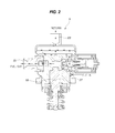
- FIG. 2 is a cross-sectional view illustrating the high pressure fuel pump used in FIG. 1 ;
- FIG. 3 is a flowchart illustrating a start control method of an LPDI engine by a controller according to an exemplary embodiment of the present invention.
- a fuel supply device for a liquefied petroleum direct injection (LPDI) engine may include a high pressure fuel pump 5 receiving fuel supplied through a supply line 3 from a fuel tank 1 and compressing fuel to a pressure higher than a pressure at which fuel has been supplied; a high pressure fuel rail 9 buffering fuel compressed by the high pressure fuel pump 5 and supplying buffered fuel to a direct injector 7 that injects fuel directly into a combustion chamber; a return line 13 connected to the supply line 3 through the high pressure fuel pump 5 to form a low pressure line 11 , the return line 13 allowing a surplus portion of fuel supplied to the high pressure fuel pump 5 from the fuel tank 1 that has not been supplied to the high pressure fuel rail 9 to return to the fuel tank 1 ; and a first valve 15 disposed on the return line 13 to control the flow rate of returning fuel.
- LPDI liquefied petroleum direct injection
- fuel supplied through the supply line 3 is received through an inlet port 17 , is compressed using a plunger 19 that reciprocally moves when the engine operates, is discharged through a high pressure port 21 , and then is supplied to the high pressure fuel rail 9 .
- the surplus portion of fuel is allowed to pass through a return port 23 and then the return line 13 to return to the fuel tank 1 .
- the inlet port 17 an the return port 23 remain substantially communicating with each other, and the supply line 3 and the return line 13 form the low pressure line 11 at the same pressure.
- the pressure of fuel in the low pressure line 11 does not have an effect on control over the pressure of fuel in the high pressure fuel rail 9 , whereby control over the pressure of fuel in the high pressure fuel rail 9 can be more accurately and reliably performed.
- the fuel supply device may further include a low pressure fuel pump 25 pumping fuel from the fuel tank 1 to feed to the high pressure fuel pump 5 through the supply line 3 ; a second valve 27 disposed within the fuel tank 1 to close the supply of fuel from the low pressure fuel pump 25 to the supply line 3 when the engine of a vehicle is turned off; a third valve 29 disposed on the supply line 3 in an engine compartment to close the supply of oil from the supply line 3 to the high pressure fuel pump 5 ; and a pressure regulator 31 regulating the pressure of fuel returning between the first valve 15 of the return line 13 and the fuel tank 1 .
- the third valve 29 has a first temperature sensor 33 measuring the temperature of fuel in the supply line 3
- the pressure regulator 31 has a first pressure sensor 35 measuring the pressure of fuel in the low pressure line 11
- the high pressure fuel rail 9 is provided with a second temperature sensor 37 measuring the temperature of fuel within the high pressure fuel rail 9 and a second pressure sensor 39 measuring the pressure of fuel in the high pressure fuel rail 9 .
- a controller 41 controls the first valve 15 by receiving signals from the first temperature sensor 33 , the second temperature sensor 37 , the first pressure sensor 35 , and the second pressure sensor 39 .
- a start control method of an LPDI engine having the above-described fuel supply device and performed by the controller 41 may include initial pressure storing step S 10 of obtaining the pressure of fuel in the low pressure line 11 and storing the obtained pressure as an initial pressure of the low pressure line 11 in response to an engine start request; reference setting step S 20 of determining a high reference start pressure that is the minimum pressure of fuel within the high pressure fuel rail 9 at which the engine can start; first high reference determination step S 30 of determining whether or not the pressure of fuel within the high pressure fuel rail 9 exceeds the high reference start pressure; first start preparation step S 40 of opening the first valve 15 of the return line 13 and operating the low pressure fuel pump 25 when the pressure of fuel within the high pressure fuel rail 9 exceeds the high reference start pressure as the result of the first high reference determination step S 30 ; first low reference determination step S 50 determining whether or not the pressure of fuel in the low pressure line 11 has reached a level sufficient for the engine to start after the start of the first start
- the pressure of fuel in the high pressure fuel rail 9 is determined whether or not to be at the level sufficient for the engine to start in the first reference determination step S 30 .
- the pressure of fuel in the low pressure line 11 is sufficiently obtained in the first start preparation step S 40 and then is determined whether or not it has reached the level sufficient for the engine to start in the first low reference determination step S 50 before the engine is started.
- the initial pressure storing step S 10 is performed by the controller 41 by determining the pressure of fuel in the low pressure line 11 using the first pressure sensor 35 disposed on the low pressure line 11 .
- the reference setting step S 20 is performed by the controller 41 using the temperature of fuel measured using the second temperature sensor 37 disposed on the high pressure fuel rail 9 .
- the first high reference determination step S 30 is performed by the controller 41 .
- the first start preparation step S 40 is performed by the controller 41 by opening the first valve 15 and controlling the low pressure fuel pump 25 .
- the first low reference determination step S 50 and the start step S 60 are performed by the controller 41 .
- the high reference start pressure is calculated by adding a correction value to a minimum start high pressure obtained from the temperature of fuel in the high pressure fuel rail 9 and a map of minimum start high pressures depending on the contents of butane of fuel in the high pressure fuel rail 9 , the correction value being set in consideration of an error.
- the correction value may be, for example, 1 bar.
- a time period in which the low pressure fuel pump 25 is to operate at a maximum speed is set using a first timer, in consideration of the temperature of cooling water of the engine. While the first low reference determination step S 50 is not satisfied after the elapse of the time period set by the first timer, the low pressure fuel pump 25 continues to be operated at the maximum speed.
- the maximum speed in which the temperature of cooling water of the engine is considered may be determined from a map or a function expression of maximum speeds of the low pressure fuel pump 25 predetermined depending on the temperature of cooling water of the engine.
- the time period set by the first timer may be, for example, 10 seconds.
- the start step S 60 is performed.
- the pressure of fuel in the low pressure line 11 is determined whether or not it has reached the level sufficient for the engine to start, based on whether or not the pressure of fuel in the low pressure line 11 is greater than a greater one of a minimum start low pressure obtained from a map of minimum start low pressures depending on the temperature of fuel in the low pressure line 11 and the contents of butane of fuel in the low pressure line 11 and a pressure obtained by adding a confirming correction pressure to the initial pressure of the initial line 11 stored in the initial pressure storing step S 10 , the confirming correction pressure allowing a sufficient rise in the pressure of the low pressure line 11 to be determined.
- the confirming correction pressure may be 4 bars.
- the start control method of an LPDI engine may further include when the pressure of fuel in the high pressure fuel rail 9 does not exceed the high reference start pressure as the result of the first high reference determination step S 30 , second start preparation step S 70 of closing the first valve 15 of the return line 13 and operating the low pressure fuel pump 25 ; second high reference determination step S 80 of determining whether or not the pressure of fuel in the high pressure fuel rail 9 exceeds the high reference start pressure after the start of the second start preparation step S 70 ; valve opening step S 90 of opening the first valve 15 when the pressure of fuel in the high pressure fuel rail 9 exceeds the high reference start pressure as the result of the second high reference determination step S 80 ; and second low reference determination step S 100 of determining whether or not the pressure of fuel in the low pressure line 11 has reached a level sufficient for the engine to start after the start of the valve opening step S 90 .
- the start step S 100 When the pressure of fuel in the low pressure line 11 is sufficient for the engine to start as the result of the second low reference determination step S 100 , the start step S
- the second start preparation step S 70 is performed to close the first valve 15 to prevent fuel from returning and operate the low pressure fuel pump 25 as an attempt to increase the pressure of fuel in the high pressure fuel rail 9 .
- the attempt succeeds, it is attempted to start the engine through the valve opening step S 90 and the second low reference determination step S 100 .
- the first valve 15 may be in an opened or closed position before the first valve 15 is opened in the first start preparation step S 40 and before the first valve 15 is closed in the second start preparation step S 70 . Regardless of the opened or closed position, the first valve 15 is operated to be opened in the first start preparation step S 40 and is operated to be closed in the second start preparation step S 70 .
- a time period in which the low pressure fuel pump 25 is to be operated at a maximum speed is set by a second timer, the maximum speed being set in consideration of the difference between the high reference start pressure and the pressure of fuel in the high pressure fuel rail 9 and the temperature of cooling water of the engine. While the second high reference determination step S 80 is not satisfied in the time period set by the second timer, the low pressure fuel pump 25 continues to be operated at the maximum speed.
- the maximum speed set in consideration of the difference between the high reference start pressure and the pressure of fuel in the high pressure fuel rail 9 and the temperature of cooling water of the engine is obtained from a map previously constructed through a number of experiments and analyses.
- the time period set by the second timer may be, for example, 10 seconds.
- the start step S 60 is performed.
- the pressure of fuel in the low pressure line 11 is determined whether or not it has reached the level sufficient for the engine to start, based on whether or not the pressure of fuel in the low pressure line 11 is greater than a greater one of a minimum start low pressure obtained from a map of minimum start low pressures depending on the temperature of fuel in the low pressure line 11 and the contents of butane of fuel in the low pressure line 11 and a pressure obtained by adding a confirming correction pressure to the initial pressure of the initial line 11 stored in the initial pressure storing step S 10 , the confirming correction pressure allowing a sufficient rise in the pressure of the low pressure line 11 to be determined.
- the confirming correction pressure may be set to be, for example, 4 bars, as in the first low reference determination step S 50 .
- the start control method attempts to directly start the engine by obtaining a sufficient pressure of fuel in the low pressure line 11 when the pressure of fuel in the high pressure fuel rail 9 is sufficient to start the engine.
- the start control method attempts to start the engine after increasing the pressure of fuel in the high pressure fuel rail 9 using the first valve 15 and the low pressure fuel pump 25 . It is possible to start the engine as rapidly as possible while obtaining reliability in the start of the engine.
Landscapes
- Engineering & Computer Science (AREA)
- Chemical & Material Sciences (AREA)
- Combustion & Propulsion (AREA)
- Mechanical Engineering (AREA)
- General Engineering & Computer Science (AREA)
- Chemical Kinetics & Catalysis (AREA)
- General Chemical & Material Sciences (AREA)
- Oil, Petroleum & Natural Gas (AREA)
- Electrical Control Of Air Or Fuel Supplied To Internal-Combustion Engine (AREA)
- Combined Controls Of Internal Combustion Engines (AREA)
- Fuel-Injection Apparatus (AREA)
Abstract
Description
Claims (10)
Applications Claiming Priority (2)
| Application Number | Priority Date | Filing Date | Title |
|---|---|---|---|
| KR1020160084583A KR101866032B1 (en) | 2016-07-05 | 2016-07-05 | Fuel supply device for lpdi engine and start control method lpdi engine with the fuel supply device |
| KR10-2016-0084583 | 2016-07-05 |
Publications (2)
| Publication Number | Publication Date |
|---|---|
| US20180010537A1 US20180010537A1 (en) | 2018-01-11 |
| US10174697B2 true US10174697B2 (en) | 2019-01-08 |
Family
ID=60676740
Family Applications (1)
| Application Number | Title | Priority Date | Filing Date |
|---|---|---|---|
| US15/610,257 Active US10174697B2 (en) | 2016-07-05 | 2017-05-31 | Fuel supply device for LPDI engine and start control method of LPDI engine having the fuel supply device |
Country Status (4)
| Country | Link |
|---|---|
| US (1) | US10174697B2 (en) |
| JP (1) | JP6910209B2 (en) |
| KR (1) | KR101866032B1 (en) |
| DE (1) | DE102017210630B4 (en) |
Cited By (1)
| Publication number | Priority date | Publication date | Assignee | Title |
|---|---|---|---|---|
| US11149674B2 (en) * | 2018-07-13 | 2021-10-19 | Vitesco Technologies GmbH | Method for diagnosing a digital flow-control valve of a high-pressure fuel injection pump |
Families Citing this family (4)
| Publication number | Priority date | Publication date | Assignee | Title |
|---|---|---|---|---|
| CA2992230C (en) * | 2017-01-20 | 2020-02-18 | Power Solutions International, Inc. | Systems and methods for monitoring a fuel system |
| KR101987458B1 (en) * | 2018-03-21 | 2019-06-12 | (주)모토닉 | High pressure fuel pump and lpdi system |
| KR20200134616A (en) | 2019-05-22 | 2020-12-02 | (주)모토닉 | Piston cooling device of LPDI high-pressure fuel pump |
| EP3741983B1 (en) * | 2019-05-22 | 2023-05-03 | Motonic Corporation | High pressure fuel pump |
Citations (12)
| Publication number | Priority date | Publication date | Assignee | Title |
|---|---|---|---|---|
| JP2003269256A (en) | 2002-03-19 | 2003-09-25 | Chuo Motor Wheel Co Ltd | Liquefied gas fuel feeding system |
| JP2004150333A (en) | 2002-10-30 | 2004-05-27 | Aisan Ind Co Ltd | Fuel supply device of liquefied gas internal combustion engine |
| JP2005139910A (en) | 2003-11-04 | 2005-06-02 | Hino Motors Ltd | Fuel supply system for liquefied gas engine |
| KR100644126B1 (en) | 2005-09-09 | 2006-11-10 | 르노삼성자동차 주식회사 | Vehicle ELP fuel system and control method |
| KR20070027950A (en) | 2005-08-30 | 2007-03-12 | 현대자동차주식회사 | Fuel system control method for emergency fuel cut off in LPI vehicle |
| US20110146600A1 (en) * | 2009-12-18 | 2011-06-23 | Caterpillar Inc. | Method of cooling a high pressure plunger |
| KR20120103834A (en) | 2011-03-11 | 2012-09-20 | (주)모토닉 | Direct injection type liquefied petroleum-gas injection system and control method thereof |
| JP2014066231A (en) | 2012-09-27 | 2014-04-17 | Isuzu Motors Ltd | Supply system for liquefied gas fuel, and supply method for liquefied gas fuel |
| US20140311445A1 (en) * | 2011-06-24 | 2014-10-23 | Indopar B.V. | Method of switching from a liquefied gas fuel to a liquid fuel being provided to a direct injection combustion engine, and direct injection bi-fuel system for such an engine |
| US20150059701A1 (en) * | 2013-08-27 | 2015-03-05 | Kia Motors Corporation | Device for decreasing fuel pulsation of lpg vehicle |
| US20160084172A1 (en) * | 2013-05-30 | 2016-03-24 | Sebastiaan Martinus Emanuel TEN BROEKE | Bi-fuel system and a method for operating such a system |
| US20160160790A1 (en) * | 2014-12-04 | 2016-06-09 | Ford Global Technologies, Llc | Direct injection pump control |
Family Cites Families (6)
| Publication number | Priority date | Publication date | Assignee | Title |
|---|---|---|---|---|
| JP3333407B2 (en) * | 1996-10-17 | 2002-10-15 | 株式会社ユニシアジェックス | Fuel supply system for direct injection gasoline internal combustion engine |
| JP2004346813A (en) * | 2003-05-21 | 2004-12-09 | Toyota Motor Corp | LPG fuel engine and method of operating LPG fuel engine |
| JP2009243286A (en) * | 2008-03-28 | 2009-10-22 | Fuji Heavy Ind Ltd | Engine fuel supply system |
| US9157393B2 (en) * | 2011-02-28 | 2015-10-13 | Ford Global Technologies, Llc | Multi-staged fuel return system |
| KR101261836B1 (en) * | 2011-03-11 | 2013-05-07 | (주)모토닉 | Direct injection type liquefied petroleum-gas injection system and control method theereof |
| US9133783B2 (en) | 2012-03-07 | 2015-09-15 | Ford Global Technologies, Llc | Method and system for estimating fuel system integrity |
-
2016
- 2016-07-05 KR KR1020160084583A patent/KR101866032B1/en active Active
-
2017
- 2017-05-31 US US15/610,257 patent/US10174697B2/en active Active
- 2017-06-01 JP JP2017108978A patent/JP6910209B2/en not_active Expired - Fee Related
- 2017-06-23 DE DE102017210630.1A patent/DE102017210630B4/en not_active Expired - Fee Related
Patent Citations (13)
| Publication number | Priority date | Publication date | Assignee | Title |
|---|---|---|---|---|
| JP2003269256A (en) | 2002-03-19 | 2003-09-25 | Chuo Motor Wheel Co Ltd | Liquefied gas fuel feeding system |
| JP2004150333A (en) | 2002-10-30 | 2004-05-27 | Aisan Ind Co Ltd | Fuel supply device of liquefied gas internal combustion engine |
| JP2005139910A (en) | 2003-11-04 | 2005-06-02 | Hino Motors Ltd | Fuel supply system for liquefied gas engine |
| KR20070027950A (en) | 2005-08-30 | 2007-03-12 | 현대자동차주식회사 | Fuel system control method for emergency fuel cut off in LPI vehicle |
| KR100644126B1 (en) | 2005-09-09 | 2006-11-10 | 르노삼성자동차 주식회사 | Vehicle ELP fuel system and control method |
| US20110146600A1 (en) * | 2009-12-18 | 2011-06-23 | Caterpillar Inc. | Method of cooling a high pressure plunger |
| KR20120103834A (en) | 2011-03-11 | 2012-09-20 | (주)모토닉 | Direct injection type liquefied petroleum-gas injection system and control method thereof |
| US20140311445A1 (en) * | 2011-06-24 | 2014-10-23 | Indopar B.V. | Method of switching from a liquefied gas fuel to a liquid fuel being provided to a direct injection combustion engine, and direct injection bi-fuel system for such an engine |
| JP2014066231A (en) | 2012-09-27 | 2014-04-17 | Isuzu Motors Ltd | Supply system for liquefied gas fuel, and supply method for liquefied gas fuel |
| US20160084172A1 (en) * | 2013-05-30 | 2016-03-24 | Sebastiaan Martinus Emanuel TEN BROEKE | Bi-fuel system and a method for operating such a system |
| US20150059701A1 (en) * | 2013-08-27 | 2015-03-05 | Kia Motors Corporation | Device for decreasing fuel pulsation of lpg vehicle |
| US20160160790A1 (en) * | 2014-12-04 | 2016-06-09 | Ford Global Technologies, Llc | Direct injection pump control |
| US9957935B2 (en) * | 2014-12-04 | 2018-05-01 | Ford Global Technologies, Llc | Direct injection pump control |
Cited By (1)
| Publication number | Priority date | Publication date | Assignee | Title |
|---|---|---|---|---|
| US11149674B2 (en) * | 2018-07-13 | 2021-10-19 | Vitesco Technologies GmbH | Method for diagnosing a digital flow-control valve of a high-pressure fuel injection pump |
Also Published As
| Publication number | Publication date |
|---|---|
| DE102017210630A1 (en) | 2018-01-11 |
| US20180010537A1 (en) | 2018-01-11 |
| JP6910209B2 (en) | 2021-07-28 |
| KR101866032B1 (en) | 2018-06-11 |
| JP2018003834A (en) | 2018-01-11 |
| DE102017210630B4 (en) | 2024-07-04 |
| KR20180005293A (en) | 2018-01-16 |
Similar Documents
| Publication | Publication Date | Title |
|---|---|---|
| US10174697B2 (en) | Fuel supply device for LPDI engine and start control method of LPDI engine having the fuel supply device | |
| US7832375B2 (en) | Addressing fuel pressure uncertainty during startup of a direct injection engine | |
| US7210459B2 (en) | Common-rail fuel injection system | |
| US6615807B2 (en) | Method and apparatus for cooling a fuel injection system | |
| RU2715765C2 (en) | Method (embodiments) and system for fuel system of double injection | |
| JP2009057928A (en) | Fuel injection control device for internal combustion engine | |
| KR20010062340A (en) | Fuel injection system of internal combustion engine | |
| US9995258B2 (en) | Fuel supply device and control method | |
| US9347392B2 (en) | Control system and control method of gasoline direct injection engine | |
| JP2008248725A (en) | Fuel injection control device and fuel injection control system | |
| JP2009180136A (en) | Fuel injection device for internal combustion engine | |
| US20140299103A1 (en) | Fuel injection control device for internal combustion engine | |
| JPH1150899A (en) | Fuel injection control device for accumulator type engine | |
| JP4605038B2 (en) | Fuel injection device | |
| US9829394B2 (en) | Method for determining the fuel temperature | |
| US11035306B2 (en) | Activation response of injectors of an internal combustion engine | |
| JPH11159372A (en) | Injection control system for accumulator type multi-cylinder engine | |
| JP2012202255A (en) | Engine control device | |
| US11162449B2 (en) | Fuel pressure control device for internal combustion engine | |
| JP2014202075A (en) | Fuel injection device | |
| JP2006002698A (en) | Fuel injection device | |
| JP5768351B2 (en) | DME fuel system | |
| JP6819425B2 (en) | Common rail fuel injection system | |
| JP4689695B2 (en) | Fuel injection system | |
| JP7021597B2 (en) | Fuel injection system |
Legal Events
| Date | Code | Title | Description |
|---|---|---|---|
| AS | Assignment |
Owner name: KIA MOTORS CORPORATION, KOREA, REPUBLIC OF Free format text: ASSIGNMENT OF ASSIGNORS INTEREST;ASSIGNORS:SONG, JIN OH;KIM, DO WAN;LIM, JONG SUK;AND OTHERS;SIGNING DATES FROM 20170524 TO 20170525;REEL/FRAME:042549/0423 Owner name: HYUNDAI MOTOR COMPANY, KOREA, REPUBLIC OF Free format text: ASSIGNMENT OF ASSIGNORS INTEREST;ASSIGNORS:SONG, JIN OH;KIM, DO WAN;LIM, JONG SUK;AND OTHERS;SIGNING DATES FROM 20170524 TO 20170525;REEL/FRAME:042549/0423 Owner name: CONTINENTAL AUTOMOTIVE SYSTEMS CORPORATION, KOREA, Free format text: ASSIGNMENT OF ASSIGNORS INTEREST;ASSIGNORS:SONG, JIN OH;KIM, DO WAN;LIM, JONG SUK;AND OTHERS;SIGNING DATES FROM 20170524 TO 20170525;REEL/FRAME:042549/0423 |
|
| AS | Assignment |
Owner name: HYUNDAI MOTOR COMPANY, KOREA, REPUBLIC OF Free format text: ASSIGNMENT OF ASSIGNORS INTEREST;ASSIGNOR:CONTINENTAL AUTOMOTIVE SYSTEMS CORPORATION;REEL/FRAME:043995/0287 Effective date: 20171025 Owner name: KIA MOTORS CORPORATION, KOREA, REPUBLIC OF Free format text: ASSIGNMENT OF ASSIGNORS INTEREST;ASSIGNOR:CONTINENTAL AUTOMOTIVE SYSTEMS CORPORATION;REEL/FRAME:043995/0287 Effective date: 20171025 |
|
| STCF | Information on status: patent grant |
Free format text: PATENTED CASE |
|
| MAFP | Maintenance fee payment |
Free format text: PAYMENT OF MAINTENANCE FEE, 4TH YEAR, LARGE ENTITY (ORIGINAL EVENT CODE: M1551); ENTITY STATUS OF PATENT OWNER: LARGE ENTITY Year of fee payment: 4 |