US1017463A - Sewing-machine. - Google Patents
Sewing-machine. Download PDFInfo
- Publication number
- US1017463A US1017463A US24555905A US1905245559A US1017463A US 1017463 A US1017463 A US 1017463A US 24555905 A US24555905 A US 24555905A US 1905245559 A US1905245559 A US 1905245559A US 1017463 A US1017463 A US 1017463A
- Authority
- US
- United States
- Prior art keywords
- needle
- thread
- fabric
- reel
- driving
- Prior art date
- Legal status (The legal status is an assumption and is not a legal conclusion. Google has not performed a legal analysis and makes no representation as to the accuracy of the status listed.)
- Expired - Lifetime
Links
- 239000004744 fabric Substances 0.000 description 62
- 238000009958 sewing Methods 0.000 description 26
- 238000000034 method Methods 0.000 description 15
- 241000282472 Canis lupus familiaris Species 0.000 description 14
- 230000001276 controlling effect Effects 0.000 description 7
- 238000010276 construction Methods 0.000 description 5
- 230000015572 biosynthetic process Effects 0.000 description 3
- 238000004826 seaming Methods 0.000 description 3
- 206010028347 Muscle twitching Diseases 0.000 description 2
- 230000000694 effects Effects 0.000 description 2
- 239000000463 material Substances 0.000 description 2
- 238000005192 partition Methods 0.000 description 2
- 238000000926 separation method Methods 0.000 description 2
- 241000272470 Circus Species 0.000 description 1
- 238000010009 beating Methods 0.000 description 1
- 210000003414 extremity Anatomy 0.000 description 1
- 210000003141 lower extremity Anatomy 0.000 description 1
- 230000001105 regulatory effect Effects 0.000 description 1
- 230000013707 sensory perception of sound Effects 0.000 description 1
Images
Classifications
-
- D—TEXTILES; PAPER
- D05—SEWING; EMBROIDERING; TUFTING
- D05B—SEWING
- D05B1/00—General types of sewing apparatus or machines without mechanism for lateral movement of the needle or the work or both
- D05B1/02—General types of sewing apparatus or machines without mechanism for lateral movement of the needle or the work or both for making single-thread seams
Definitions
- This invention relates to improvements in sewing machines and relates more particularly to that class of machines in which a circular needle is utilized for the purpose of sewing together the edges of any desired fabric by an over-seaming stitch; and among the particular objects of this improvement are first to provide improved means for controlling the thread in the process of making the stitch through the fabric, also of providing improved tension and takeup devices for drawing tension on the thread at the proper time in the process of making the stitch and also taking up unnecessary slack in this process; also an improved form of thread supply reel; and also providing such a novel form of assembling of the various parts of the machine as will combine the same into compact form and will moreover insure certainty of operation in the various phases of the needle movement in making the desired over-seaming stitch.
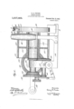
- Figure 1 represents a side elevation of a machine embodying the aforesaid improvements.
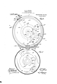
- Fig. 2 represents a cross-section approximately on the line 22 of Fig. 1, looking in the direction of the arrow crossing said line, showing the circu' lar needle, the dogs for operating the same, and'parts of the tension and take-up devices.
- Fig. 3 represents a detail view of the socalled dead plate carrying the cam for operating the needle dogs and also carrying portions of the tension and'take-up devices.
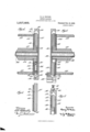
- Fig. 4 represents a fragmentary section taken diagonally through the needle-carrying end of the machine on the line tt of Fig. 2.
- Fig. 5 represents a similar frag- Specification of Letters Patent.
- Fig. 6 represents an enlarged detail fragmentary section of a portion of the dead-plate and of the needle carrying head showing the take up device.
- Fig. 7 represents a fragmentary detail sectional view showing the tension device.
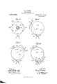
- Figs. 8, 9, and 10 represent diagrammatic views of different stages of the process of stitching.
- Fig. 11 represents a diagrammatic view-of the supply thread passing over the storage reel and through the fabric.
- the two edges of the fabric desired to be sewed are first brought together in any suitable manner such for example as suspending the same over a suitable guide wire, and then the' machine is placed above the edges of the material in proper position to have the needle when operated engage and pass through the fabric, the machine being held in position by hand, and-by rotation of a suitable crank handle the needle is given a rotation in a circular path and passes successively through and through the fabric being automatically fed between the successive stitches so that the machine itself moves along the fabric producing an over-seaming stitch as it moves; and the thread for the needle is provided by a so-called thread reel which is driven at a different speed from the needle so as to permit the formation of the stitch, and by mechanism which will be later described the thread is so controlled as to insure the tightening of the same in the process of making each stitch, and means are also provided for separating the two strands of thread at the stitching point when these two threads are carried through the fabric by the needle so that one of
- the crank handle 10 is mounted upon a shaft turning in suitable hearings in the framework 11 of the machine and carries a beveled gear wheel 12 which meshes with a smaller beveled gear wheel 13, which gear 13 is fast upon the lefthand end of a shaft lat shown in Figs. el and 5, which shaft extends through to the other end of the machine to impart movement to the needle as will be later described.
- Fast to the beveled gear 13 is a gear wheel 15 which meshes with a smaller gear wheel 16 fast upon a shaft 17 which upon its righthand end has fast a larger gear wheel 18, the shaft 17 being mounted to turn in the framework 11 of the machine.
- the gear wheel 18 meshes with another gear wheel 19 which is fast upon the end of a collar 20 shown also in Figs. 4 and 5, this collar surrounding an inner sleeve 21, which sleeve 21 surrounds the aforesaid shaft lat and forms a bearing for the rotation collar 20.
- the collar 20 forms the hub portion of the thread-carrying reel 22, the outer portion of the reel being formed by rods 23 extending between disks 24, rigidity being given to the lugs by means of the spokes
- the purpose of this reel is to carry the supply, of thread for the needle as will be later de scribed.
- a stationary circular head 30 within which revolves the circular needle and the needle driving head as will now be explained.
- the interior portion of the head 30 is formed with a needle groove 31 shown in cross-section in Figs. if and 5, this groove being arranged to receive and hold in place the rotary circular needle 32 as shown in Fig. 2, the needle being caused to rotate in the circular path of this groove, and the means for driving the needle constituting threedogs or plungers 33 which have enlarged inner ends 34- and at the inner end of each of these enlarged ends is an anti-friction roller 35 which rolls around the periphery of a stationary cam 36 (see also Fig. 3).
- These needle dogs are carried in a needle driving head 37 shown in cross-section in Figs.
- this head being fast upon the extremity of the aforesaid shaft 1st so as to receive rotary motion from said shaft.
- the outer ends of the aforesaid dogs are beveled to fit into corresponding notches formed on the inner side of the grooved needle 32 so that the dogs in their rotary movement engage with and carry about its circular groove path the needle 32.
- a stationary guide block 40 having two slots 4-1 formed therein intended to receive the edges of the fabric to be sewed so as to hold the fabric in proper position to permit the point of the needle 32 to pass therethrough, the guide block 40 of course being situated just to one side of the path of the needle so that the needle may pass freely along one end of the guide block and thereby pass through the fabric.
- the lower part of the block 40, between the converging slots 41, is formed with a vertical. slot such as is shown in Fig. 2 which engages the guide wire hitherto referred to upon which the material is hung, so as to support the machine on said guide wire in this manner.
- the driving dog which is in lowermost position at such time should of course be retracted so as not to engage the fabric and this result is accomplished by means of the recess 4-3 formed in the cam 36 as shown both in Figs. 2 and 3 so that the lowermost dog as it arrives in this vertical position is forced upward by its spring tensionto engage in said recess and be retracted from the needle while the other two dogs are the driving power until the retracted dog has been moved far enough to be carried past the recess 43 and it is then forced outward again to engage the needle.
- the center portion of this deadplate comprises the cam 36, the recessed portion 43 being shown in Fig. 5, and the remaining portion of this circular dead-plate extends alongside of the circular end plate 24 of the previously described thread reel 22, and at its outer periphery is formed with a flange 51 extending partially over the outer periphery of the revolving needle driving head 37, and also being formed with another flange 52 which projects over the side plate 24: of the reel.
- this dead plate is to assist in holding and in guiding the thread from the needle back upon the reel in the course of the revolving movement of the needle, as will be later described, and the flange 52 projecting over the end plate of the reel prevents the thread from falling down between the dead-plate and the end of the reel and thus insures the thread being properly conveyed back to the reel.
- a tension plate 55 Seated in a suitable channel in the upper portion of this dead-plate is a tension plate 55 (see Figs. 2 and 3), the inner end of which is beveled to be engaged by a cam flangebti carried upon the adjoining side of the revolving head 37 as shown in Figs. a and 5.
- This cam is such as to cause the inward and outward reciprocation of the plate 55 radially at certain periods for the purpose to be described, and when so forced out-ward, the plate 55 abuts against a shoe 57 pivoted to the outer casing or head 30 at 58 and having at its outer end an adjusting device comprising an arm 59 in one end of which is carried a set screw 60 and the other end of which is springpressed upward by means of a spring 61 so that by adjustment of the set screw against the tension of the spring the shoe 57 can be tilted more or less to cause greater or less pressure between the plate 55 and the shoe 57 when the plate 55 is forced outward.
- the purpose of this tension or stitch tightening device is to grip and hold fast the thread at a certain point in the operation of making the stitch as will be set forth hereinafter. This tension device is also shown in detail in Fig. 7.
- the dead-plate 50 as shown in Fig. 3 has seated in it a take-up slide 62 which is arranged to be projected outwardly from said dead-plate at a certain time and at its lower end has a foot 63 which projects through the periphery of the dead-plate and is arranged to engage the thread at the desired time.
- the take-up slide 62 is held retracted by a spring 64, and is operated to be forced outward to engage the thread by means of a pin 65' (see Figs. 2 and 6) carried upon the adjoining side of the revolving needle driving head 37, so that upon the revolution of the head in the direction shown by the arrow in Fig. 2 the pin 65 will strike the lateral flange 66 at the inner end of the slide 62 and will force the slide outward against its spring tension until the pin has reached such position as to permit the slide to spring backward.
- a so-called thread divider 70 (see Figs. 2, 3 and 5).
- This divider is fast to the lower edge of the dead plate 50 and comprises a tongue which is situated on the opposite side of the fabric from the point of approach of. the needle and the lower extremity of this divider projects into such proximity with the needle as shown in Fig. 5, that when the needle has passed through the fabric, carrying the thread which passes through the needle eye 71 and extends on either side of the needle, the divider 70 will serve to keep the two strands of thread properly separated during the continued movement of the needle, this separation of the thread being of the greatest importance in insuring the proper operation of the machine.
- the fabric to be used may as heretofore suggested be suspended by means of wires or other suitable apparatus and the edges to be sewn together are inserted into the aforesaid guide slots ll formed in the guide block 40, the entire machine being held suspended over the fabric by means of the handle (see Fig. 1) attached to the frame work 11 of the machine, and driving power is imparted as heretofore described by means of the rotation of the crank 10, and by means of suitable mechanism connected with the main driving gears of the machine a feed shaft 81 is operated to cause the feeding of the machine over the fabric so that the machine will be advanced'in the process of making the successive stitches.
- any suitable form of such feeding mechanism may be used and no further description will be given of the same as in itself it constitutes no part of the present invention.
- the operation of the needle and the thread can best be explained by reference to the diagrammatic Figs. 8, 9 and 10.
- the needle In order to start the machine with the necessary supply of thread, the needle is inserted into its circular race-way and the thread is passed through the eye 71 of the needle and is knotted as usual (as at 85, Figs. 8 and 9), the knot end of the thread being on the side of the needle farthest from the thread reel. Then upon the revolution of the crank 10 the needle is revolved in the direction shown by the arrow in Fig.
- this inner strand of thread 91 has then been rolled around the outer circumference of this dead-plate as shown diagrammatically in Fig. 9, and in such position the tension plate 55 may then be operated by its cam 56 to carry the tension plate against its clamping shoe 57 so that this strand of thread which has thus been rolled over the dead-plate will now be se curely clamped by this tension or stitch tightening device.
- the strand 90 has been drawn from the far side of the fabric over the two edges thereof and is in position again to be carried through the fabric, thus forming the stitch, and at this point the take-up device 2 is camm'ed downward so as to engage the strand of thread 91 coming from the dead-plate, and take up the slack in the thread by pulling the thread through the eye of the needle and thus pulling the strand 90 tight and maintaining the same tight until the needle has advanced far enough to again pull this strand through the fabric to begin another stitch; and as soon as the needle eye has again started through the fabric both the tension device and the take-up device are released so that the strand of thread 91 is now free and the continued movement of the needle through the fabric begins to draw upon this strand 91 to get new supply for continuing the same operation which has been just above described.
- the reel comprises an open-work construction formed by the rods 23 extending between the side plates 24 and the supply thread simply Winds around upon these horizontal rods as shown diagrammatically in Fig. 11.
- the ratio of the gearing which drives this reel is such that the sleeve 20 carrying the reel is revolved approximately four times as fast as the shaft 1% carrying the needle driving head, revolves; so that while the needle is revolving, the storage reel is also revolving in the same direct-ion but at a. more rapid rate to assist in carrying forward the supply thread which is contained upon the storage reel.
- the thread will be given a constant vibratory motion due to the fact of course that the cross-rods 23 are constantly changing position, and this movement assists in the feeding forward of the supply thread through the different stitches; and furthermore the unevenness of the contour of this storage reel has this further effect in assisting the pulling of the thread through the various holes, namely: that when the reel is in the position shown in Fig.
- a sewing machine the combination with a curved needle, of a driving member for the same, a storage member for supporting a supply of thread for the needle, a stationary member interposed between said storage member and said driving member, said stationary member having provisions for supporting one of the strands of thread during the process of forming the stitch.
- said stationary member having provisions for dividing the strands of thread as they are carried through the fabric by the needle and also having provisions for holding one of said strands taut during the process of forming the stitch.
- a sewing machine the combination with a curved needle, of a driving member for the same, a storage member for supporting a supply of thread for the needle, a stationary member interposed between said storage member and said driving member, and means carried by said stationary member for holding one of the strands of thread taut during the process of forming the stitch, and a take-up means also carried by said stationary member for taking up unnecessary slack in the thread.
- a rotary thread-supporting reel comprising a plurality of rods for supporting the thread thereupon, and means for rotating said reel.
- a rotary driving head for driving the needle in a circular path
- a thread supply reel for supporting thread for the needle, said supply reel being mounted co-axially with said rotary needle driving head; and a stationary plate located between said reel and said needle driving head and having provision for dividing the strands of thread after the needle passes through the fabric.
- a sewing machine the combination with a curved needle, a casing having a circular groove formed therein to form a circular path for said needle, and a needle driving head revolving within said casing and having means for carrying said needle around said groove; of a thread supply cylinder mounted co-axially with said needle driving head; and a stationary plate located between said thread cylinder and said driving head and formed with a projection extending into proximity to the needle at the point where the needle passes through the fabric, for dividing the strands of thread after the needle has passed through the fabric.
- a supply of thread for said needle for said needle; and a stationary plate mounted on said shaft between the end of said supply reel and said needle driving head, said stationary plate being formed with a projection extending into proximity with the needle at the point where the needle passes through the fabric and operating to divide the strands of thread to carry one strand over said supply reel and the other strand across the free face of said needle driving head through the above mentioned space between the said head and said casing.
- a rotary needle driving head having provisions for engaging the needle and driving it around said circular path; a central operating shaft attached to and rotating said driving head; a thread supply reel mounted co-axially with said shaft; and a stationary plate intervening between said supply reel and said driving head and carrying provisions for controlling the thread in the operation of forming the stitch, said stationary plate being provided with circumferential flanges extending over said driving head and said supply reel.
- a rotary needle driving head having provisions for engaging the needle and driving it around said circular path; a central operating shaft attached to and rotating said driving head; a thread supply reel mounted co-axially with said shaft; a stationary plate intervening between said supply reel and said driving head and carrying provisions for controlling the thread in the operation of forming the stitch, said stationary plate being provided with circumferential flanges extending over said driving head and said supply reel, and also being provided with cam devices for controlling the needle driving means.
- a rotary needle driving head having provisions for engaging the needle and driving it aroundsaid circular path; a central operating shaft attached to and rotating said driving head; a thread supply reel mounted coaxially with said shaft; a stationary plate intervening between said supply reel and said driving head and carrying provisions for controlling the thread in the-operation of forming the stitch,said stationary plate being provided with circumferential flanges extending over said driving head and said supply reel, also being provided with cam devices for controlling the needle driving means, and also having mounted thereon a stitch tightening device.
Landscapes
- Engineering & Computer Science (AREA)
- Textile Engineering (AREA)
- Sewing Machines And Sewing (AREA)
Description
H. B. PRUDEN. SEWING MACHINE. PPPPPPPPPPPP ILBI) 313.14, 1905. 1,01 7,463.
i l} f M O! lllllfllllll :1 l m R I \Q uy-4 g M QM v 4r W HUW-HI'WIWJIII'II H. B. PRUDEN.
SEWING MACHINE.
APPLICATION FILED 1 53.14, 1905.
n6 1 9 1 3 1 w F d .w n L b a P 2 T E E H Jb S T E E H S 4 H. B. PRUDEN.
SEWING MACHINE.
APPLIOATION FILED 312.14, 1905. 1,017,463. Patented Feb. 13,1912.
4 SHEETS-SHEET 3.
couqmau PLANMRAPH 60.. wAsmNnroN, n. c
H.B.PRUDEN, SEWING MACHINE. APPLICATION FILED PERM, 1905.
Patented Feb/13, 1912;
4 SEEETSSHBET 4.
UNITED STATES PATENT ormos.
HENRY B. PRUDEN, 0F DAYTON, OHIO, ASSIGNOR, BY MESNE ASSIGNMENTS, TO
REUBEN F. MYERS, TRUSTEE, 0F DAYTON, OHIO.
SEWING-MACHINE.
To all whom it may concern:
Be it known that I, HENRY B. PRUDEN, a citizen of the United States, residing at Dayton, in the county of Montgomery and State of Ohio, have invented certain new and useful Improvements in Sewing-Vlachines, of which I declare the following to be a full, clear, and exact description.
This invention relates to improvements in sewing machines and relates more particularly to that class of machines in which a circular needle is utilized for the purpose of sewing together the edges of any desired fabric by an over-seaming stitch; and among the particular objects of this improvement are first to provide improved means for controlling the thread in the process of making the stitch through the fabric, also of providing improved tension and takeup devices for drawing tension on the thread at the proper time in the process of making the stitch and also taking up unnecessary slack in this process; also an improved form of thread supply reel; and also providing such a novel form of assembling of the various parts of the machine as will combine the same into compact form and will moreover insure certainty of operation in the various phases of the needle movement in making the desired over-seaming stitch.
Vith these and incidental objects in view, the invention consists of certain novel features of construction and combinations of parts, the essential elements of which are set forth in the appended claims and a preferred form of embodiment of which is hereinafter specifically described with reference to the drawings which accompany and form part of this specification.
Of said-drawings: Figure 1 represents a side elevation of a machine embodying the aforesaid improvements. Fig. 2 represents a cross-section approximately on the line 22 of Fig. 1, looking in the direction of the arrow crossing said line, showing the circu' lar needle, the dogs for operating the same, and'parts of the tension and take-up devices. Fig. 3 represents a detail view of the socalled dead plate carrying the cam for operating the needle dogs and also carrying portions of the tension and'take-up devices. Fig. 4 represents a fragmentary section taken diagonally through the needle-carrying end of the machine on the line tt of Fig. 2. Fig. 5 represents a similar frag- Specification of Letters Patent.
Application filed February 14, 1905.
Patented Feb. 13, 1912.
Serial No. 245,559.
mentary section but taken vertically on the line 55 of Fig. 2. Fig. 6 represents an enlarged detail fragmentary section of a portion of the dead-plate and of the needle carrying head showing the take up device. Fig. 7 represents a fragmentary detail sectional view showing the tension device. Figs. 8, 9, and 10 represent diagrammatic views of different stages of the process of stitching. Fig. 11 represents a diagrammatic view-of the supply thread passing over the storage reel and through the fabric.
As a description of the general operation of the machine it may be stated that the two edges of the fabric desired to be sewed are first brought together in any suitable manner such for example as suspending the same over a suitable guide wire, and then the' machine is placed above the edges of the material in proper position to have the needle when operated engage and pass through the fabric, the machine being held in position by hand, and-by rotation of a suitable crank handle the needle is given a rotation in a circular path and passes successively through and through the fabric being automatically fed between the successive stitches so that the machine itself moves along the fabric producing an over-seaming stitch as it moves; and the thread for the needle is provided by a so-called thread reel which is driven at a different speed from the needle so as to permit the formation of the stitch, and by mechanism which will be later described the thread is so controlled as to insure the tightening of the same in the process of making each stitch, and means are also provided for separating the two strands of thread at the stitching point when these two threads are carried through the fabric by the needle so that one of the threads remains to form the stitch and the other thread is led back to the thread reel, the stitch being simply a continuous running of the thread, first through the fabric and over the edge and through the fabric again just as the fabric would be sewed in the simplest manner by hand. With this general description of the mode of operation of the machine the different parts will now be described in detail.
Referring to Fig. 1, the crank handle 10 is mounted upon a shaft turning in suitable hearings in the framework 11 of the machine and carries a beveled gear wheel 12 which meshes with a smaller beveled gear wheel 13, which gear 13 is fast upon the lefthand end of a shaft lat shown in Figs. el and 5, which shaft extends through to the other end of the machine to impart movement to the needle as will be later described. Fast to the beveled gear 13 is a gear wheel 15 which meshes with a smaller gear wheel 16 fast upon a shaft 17 which upon its righthand end has fast a larger gear wheel 18, the shaft 17 being mounted to turn in the framework 11 of the machine. The gear wheel 18 meshes with another gear wheel 19 which is fast upon the end of a collar 20 shown also in Figs. 4 and 5, this collar surrounding an inner sleeve 21, which sleeve 21 surrounds the aforesaid shaft lat and forms a bearing for the rotation collar 20. The collar 20 forms the hub portion of the thread-carrying reel 22, the outer portion of the reel being formed by rods 23 extending between disks 24, rigidity being given to the lugs by means of the spokes The purpose of this reel is to carry the supply, of thread for the needle as will be later de scribed.
Upon the right-hand end of the machine is a stationary circular head 30 within which revolves the circular needle and the needle driving head as will now be explained. The interior portion of the head 30 is formed with a needle groove 31 shown in cross-section in Figs. if and 5, this groove being arranged to receive and hold in place the rotary circular needle 32 as shown in Fig. 2, the needle being caused to rotate in the circular path of this groove, and the means for driving the needle constituting threedogs or plungers 33 which have enlarged inner ends 34- and at the inner end of each of these enlarged ends is an anti-friction roller 35 which rolls around the periphery of a stationary cam 36 (see also Fig. 3). These needle dogs are carried in a needle driving head 37 shown in cross-section in Figs. 4 and 5, this head being fast upon the extremity of the aforesaid shaft 1st so as to receive rotary motion from said shaft. The outer ends of the aforesaid dogs are beveled to fit into corresponding notches formed on the inner side of the grooved needle 32 so that the dogs in their rotary movement engage with and carry about its circular groove path the needle 32. Below the stationary head 30 and attached to the framework 11 of the machine is inserted a stationary guide block 40 having two slots 4-1 formed therein intended to receive the edges of the fabric to be sewed so as to hold the fabric in proper position to permit the point of the needle 32 to pass therethrough, the guide block 40 of course being situated just to one side of the path of the needle so that the needle may pass freely along one end of the guide block and thereby pass through the fabric. The lower part of the block 40, between the converging slots 41, is formed with a vertical. slot such as is shown in Fig. 2 which engages the guide wire hitherto referred to upon which the material is hung, so as to support the machine on said guide wire in this manner. When the needle passes through the fabric the driving dog which is in lowermost position at such time should of course be retracted so as not to engage the fabric and this result is accomplished by means of the recess 4-3 formed in the cam 36 as shown both in Figs. 2 and 3 so that the lowermost dog as it arrives in this vertical position is forced upward by its spring tensionto engage in said recess and be retracted from the needle while the other two dogs are the driving power until the retracted dog has been moved far enough to be carried past the recess 43 and it is then forced outward again to engage the needle. It may be stated that these enlarged ends 3% of these driving dogs are seated in channels formed in the needle driving head 37 so that they may have radial movement along these channels a l and the springs 45 at the ends of these channels serve to force the dogs inward against the periphery of the operating cam. The aforesaid cam disk 36 by means of which the needle driving dogs are reciprocated to engage the needle, is mounted upon a so-called dead-plate 50 shown in full view in Fig. 3, and in cross-section in Figs. 4 and 5. This dead-plate is fast to the stationary sleeve 21 previously described as surrounding the shaft 14:, and as shown in cross-section in Figs. 4 and 5 the center portion of this deadplate comprises the cam 36, the recessed portion 43 being shown in Fig. 5, and the remaining portion of this circular dead-plate extends alongside of the circular end plate 24 of the previously described thread reel 22, and at its outer periphery is formed with a flange 51 extending partially over the outer periphery of the revolving needle driving head 37, and also being formed with another flange 52 which projects over the side plate 24: of the reel. One of the purposes of this dead plate is to assist in holding and in guiding the thread from the needle back upon the reel in the course of the revolving movement of the needle, as will be later described, and the flange 52 projecting over the end plate of the reel prevents the thread from falling down between the dead-plate and the end of the reel and thus insures the thread being properly conveyed back to the reel. Seated in a suitable channel in the upper portion of this dead-plate is a tension plate 55 (see Figs. 2 and 3), the inner end of which is beveled to be engaged by a cam flangebti carried upon the adjoining side of the revolving head 37 as shown in Figs. a and 5. The shape of this cam is such as to cause the inward and outward reciprocation of the plate 55 radially at certain periods for the purpose to be described, and when so forced out-ward, the plate 55 abuts against a shoe 57 pivoted to the outer casing or head 30 at 58 and having at its outer end an adjusting device comprising an arm 59 in one end of which is carried a set screw 60 and the other end of which is springpressed upward by means of a spring 61 so that by adjustment of the set screw against the tension of the spring the shoe 57 can be tilted more or less to cause greater or less pressure between the plate 55 and the shoe 57 when the plate 55 is forced outward. The purpose of this tension or stitch tightening device is to grip and hold fast the thread at a certain point in the operation of making the stitch as will be set forth hereinafter. This tension device is also shown in detail in Fig. 7.
For the purpose of taking up slack at a certain point in the operation of forming the stitch, the dead-plate 50 as shown in Fig. 3 has seated in it a take-up slide 62 which is arranged to be projected outwardly from said dead-plate at a certain time and at its lower end has a foot 63 which projects through the periphery of the dead-plate and is arranged to engage the thread at the desired time. The take-up slide 62 is held retracted by a spring 64, and is operated to be forced outward to engage the thread by means of a pin 65' (see Figs. 2 and 6) carried upon the adjoining side of the revolving needle driving head 37, so that upon the revolution of the head in the direction shown by the arrow in Fig. 2 the pin 65 will strike the lateral flange 66 at the inner end of the slide 62 and will force the slide outward against its spring tension until the pin has reached such position as to permit the slide to spring backward.
For the purpose of insuring the separation of the two strands of thread when they are pulled through the fabric by the needle, there is provided a so-called thread divider 70 (see Figs. 2, 3 and 5). This divider is fast to the lower edge of the dead plate 50 and comprises a tongue which is situated on the opposite side of the fabric from the point of approach of. the needle and the lower extremity of this divider projects into such proximity with the needle as shown in Fig. 5, that when the needle has passed through the fabric, carrying the thread which passes through the needle eye 71 and extends on either side of the needle, the divider 70 will serve to keep the two strands of thread properly separated during the continued movement of the needle, this separation of the thread being of the greatest importance in insuring the proper operation of the machine.
The general operation of the machine will now be described. For convenience in sewing, the fabric to be used may as heretofore suggested be suspended by means of wires or other suitable apparatus and the edges to be sewn together are inserted into the aforesaid guide slots ll formed in the guide block 40, the entire machine being held suspended over the fabric by means of the handle (see Fig. 1) attached to the frame work 11 of the machine, and driving power is imparted as heretofore described by means of the rotation of the crank 10, and by means of suitable mechanism connected with the main driving gears of the machine a feed shaft 81 is operated to cause the feeding of the machine over the fabric so that the machine will be advanced'in the process of making the successive stitches. Any suitable form of such feeding mechanism may be used and no further description will be given of the same as in itself it constitutes no part of the present invention. The operation of the needle and the thread can best be explained by reference to the diagrammatic Figs. 8, 9 and 10. In order to start the machine with the necessary supply of thread, the needle is inserted into its circular race-way and the thread is passed through the eye 71 of the needle and is knotted as usual (as at 85, Figs. 8 and 9), the knot end of the thread being on the side of the needle farthest from the thread reel. Then upon the revolution of the crank 10 the needle is revolved in the direction shown by the arrow in Fig. 2 and is carried through the fabric, and the knot is of course caught by the fabric and as the needle is forced through the other side of the fabric two strands of thread are pulled through the ap erture with the needle, the supply thread coming from any suitable spool, the process being to unwind as much thread as will be necessary from this spool on to the thread reel 22 in the manner to be described and then severing the thread from its spool and using this thread reel to .give the necessary supply of thread for the continued stitching process. As shown in Fig. 8, when the needle has passed through the fabric the two strands of thread of course are pulled through with the needle, extending from the eye of the needle to the fabric, and the divider 7 0 serves to keep these two strands entirely separate. Upon the continued movement of the needle in its circular path, of course more thread is drawn by the needle from the source of supply, being pulled through the fabric, and the strand of thread which is farthest from the thread reel is carried over the outside surface of the revolving head 37, there being space enough between this head 37 and the outside casing 31 to permit the thread to pass therebetween, this space being shown in Figs. 4 and 5. The other strand of thread 91, having been divided from the first mentioned strand. by the divider is led toward the thread reel, but does not immediately wind around this reel, being led along the periphery of the dead-plate 50. When the needle has been revolved to the position shown in Fig. 9, this inner strand of thread 91 has then been rolled around the outer circumference of this dead-plate as shown diagrammatically in Fig. 9, and in such position the tension plate 55 may then be operated by its cam 56 to carry the tension plate against its clamping shoe 57 so that this strand of thread which has thus been rolled over the dead-plate will now be se curely clamped by this tension or stitch tightening device.
In the (iliagrammatic Figs. 8, 9 and 10 the circumference of the driving head 37 is shown in full lines and the circumference of the dead-plate is shown in dotted lines, the diameter of the dead-plate being less than that of the head 37, and the thread 91 for the purpose of clearness is shown slightly separated from the dead-plate, itof course being understood that the thread would lie directly upon the outer circumference of this dead plate.
hen the needle has reached the position shown in Fig. 9 where the tension or stitch tightening device operates as just above described to force the plate upward to grip the thread 91, it will then be seen that the thread 90 held fast at the fabric by reason of the knot 85 and the thread 91 is held practically fast at the tension device, although this tension device may be regulated by its set screw to permit a slight amount of slipping of the thread when necessary; and the two strands of thread 90 and 91 thus being held fast at these two points, the needle in its continued revolution simply slides around on these two threads as a loop, the thread riilnning through the eye of the needle. Now when the needle reaches the position shown in, Fig. 10, of course the strand 90 has been drawn from the far side of the fabric over the two edges thereof and is in position again to be carried through the fabric, thus forming the stitch, and at this point the take-up device 2 is camm'ed downward so as to engage the strand of thread 91 coming from the dead-plate, and take up the slack in the thread by pulling the thread through the eye of the needle and thus pulling the strand 90 tight and maintaining the same tight until the needle has advanced far enough to again pull this strand through the fabric to begin another stitch; and as soon as the needle eye has again started through the fabric both the tension device and the take-up device are released so that the strand of thread 91 is now free and the continued movement of the needle through the fabric begins to draw upon this strand 91 to get new supply for continuing the same operation which has been just above described. It will be noticed however that before the needle has entered the fabric for the next stitch, the machine has been fed along so that the needle will pierce the fabric at a point farther along, this feed of the machine being to the right when viewing the machine as shown iii Fig. 1, or with reference to Figs. 8, 9 and 10 the feed of the machine is upward from the plane of the paper. This feeding movement now having taken place the strand of thread 91 which has just been reeled over the dead-plate is new set free from the dead-plate and the feeding movement of the machine simply permits the thread to slide from off the dead-plate on to the revolving reel 22, and in the continued advance movement of the needle the repetition of this same process is effected and the new strand 91 is led up over the dead plate during the formation of the next stitch, so that by this means the thread 90 which always passes over the outer surface of the head 37, is the thread which forms the stitch by going through the fabric and then over the outside edges and again through the fabric thus forming a spiral or over-seam. ing stitch to join the two edges of the fabric; but the threads 91 which have been successively led over the dead-plate, are passed along on to the reel 22 so that they form a series of convolutions of thread passing over the reel and through the successive holes in the fabric through which pass the other strand of thread forming the stitch; and when a sufiicient supply of thread has once been drawn on to the reel by the rotary movement of the needle as above described the thread is severed from its supply spool so that the reel now constitutes a supply of thread which the continued rotary movement of the needle draws upon, first pulling a certain amount of thread from off the reel as the needle goes onward through the fab ric, and then leading the thread back first on to the dead-plate and then'back on to the reel, the resultant loss of thread from the reel supply for each revolution of the needle being only such length as was used in forming the stitch. Now, as before stated, the successive convolutions of thread 011 the reel, pass through the successive stitch-holes in the fabric and of course as the needle draws upon these convolutions of thread for the supply, the tail end of the thread will in turn be pulled through one stitchhole in the fabric, then around the reel, then through the next hole, lagging behind the needle by a number of stitches according to the supply of thread wound upon the reel, and finally as the entire supply of thread is exhausted by the process of stitching, the tail end of the thread will have been pulled successively through each stitch-hole of the fabric. The construction of this thread sup ply reel forms an important part of the present invention.
As has already been stated, the reel comprises an open-work construction formed by the rods 23 extending between the side plates 24 and the supply thread simply Winds around upon these horizontal rods as shown diagrammatically in Fig. 11. The ratio of the gearing which drives this reel is such that the sleeve 20 carrying the reel is revolved approximately four times as fast as the shaft 1% carrying the needle driving head, revolves; so that while the needle is revolving, the storage reel is also revolving in the same direct-ion but at a. more rapid rate to assist in carrying forward the supply thread which is contained upon the storage reel. It has been found that when a reel of continuous surface is used, such for example as arevolving cylinder, the running of the thread over this cylinder leads to a marked disadvantage in view of the friction on the cylinder which eventually leads to the tightening up of the thread upon the drum when the thread is attempted to be pulled forward by the needle during the stitching process, the thread acting upon the cylinder as it would upon a pulley. Furthermore it will be observed that when the reel is revolving in the direction shown by the arrow in Fig. 11 the thread will be given a constant vibratory motion due to the fact of course that the cross-rods 23 are constantly changing position, and this movement assists in the feeding forward of the supply thread through the different stitches; and furthermore the unevenness of the contour of this storage reel has this further effect in assisting the pulling of the thread through the various holes, namely: that when the reel is in the position shown in Fig. 11 with one of the rods 23 in its lowest position, the continued advance movement of the reel in the direction shown by the arrow will carry this lowermost rod up against the thread coming from the far side of the fabric so as to impart a certain impact thereto and this is in effect a sort of twitching movement of the thread similar to what might be produced by hand to pull the thread through the hole in the fabric, and of course the next rod in the rear of the aforesaid rod is at this same time retreating from its thread on the near side of the fabric so as to leave a slight amount of slack in this thread and thus more effectually permitting this twitching movement; and since as above described there is a whole series of convolutions of this supply thread extending through the successive stitch-holes, the continuous beating of the rods as they successively strike these different strands of thread on the far side of the fabric, materially assists in feeding the thread forward to form a supply for the needle, and prevent the tightening up of the threads as the needle advances in its stitching movement.
WVhile the form of mechanism here shown and described is admirably adapted to fulfil the objects primarily stated, it is to be understood that it is not intended to confine the invention to the one form of embodiment herein disclose for it is susceptible of embodiment in various forms, all coming within the scope of the claims which follow.
Having thus described my invention, what I claim as new and desire to secure by Letters Patent is: i
1. In a sewing machine, the combination with a curved needle, of a driving member for driving said needle, a storage member for supporting a supply of thread for the needle, and a stationary member interposed between said driving member and said storage member.
2. In a sewing machine, the combination with a curved needle, and a rotary driving member cooperating with means for engaging said needle and driving the same in a circular path, of a stationary member situated in juxtaposition to said driving mem-' her and. said needle and having provisions for dividing the strands of thread at the point where said strands are carried through the fabric by the needle.
3. In a sewing machine, the combination with a curved needle, and means for driving the same in a circular path, of means operating at the point where the strands of thread are carried through the fabric by the needle for dividing said strands at said point.
4. In a sewing machine, the combination with a curved needle, of a member for driving the same, a storage member for supporting a supply of thread for the needle, a
stationary member interposed between said driving member and said storage member, and dividing means carried by said stationary member for dividing the strands of thread as they are carried through the fabric by the needle.
5. In a sewing machine, the combination with a curved needle, of a driving member for the same, a storage member for supporting a supply of thread for the needle, a stationary member interposed between said storage member and said driving member, said stationary member having provisions for supporting one of the strands of thread during the process of forming the stitch.
6. In a sewing machine, the combination with a curved needle, of a driving member for the same, a storage member for supporting a supply of thread for the needle, a stationary member interposed between said storage member and said driving member, said stationary member carrying provisions for holding the thread tight during the process of forming the stitch.
7 In a. sewing machine, the combination with a curved needle, of a driving member for the same, a storage member for supporting a supply of thread for the needle, astationary member interposed between said storage member and said driving member,
said stationary member having provisions for dividing the strands of thread as they are carried through the fabric by the needle and also having provisions for holding one of said strands taut during the process of forming the stitch.
8. In a sewing machine, the combination with a curved needle, of a driving member for the same, a storage member for supporting a supply of thread for the needle, a stationary member interposed between said storage member and said driving member, and means carried by said stationary member for holding one of the strands of thread taut during the process of forming the stitch, and a take-up means also carried by said stationary member for taking up unnecessary slack in the thread.
9. In asewing machine, the combination with a needle and means for driving the same, of a supporting member for supplying thread to said needle; means for conducting successive convolutions of thread over said revoluble supporting member; said supporting member having its thread supporting surface formed with spaced thread contacting elements extending parallel to the axis of rotation of said member.
10. In a sewing machine, the combination with a needle and means for driving the same, of a supporting member of open-work construction for supporting supply thread for said needle, said open-work construction extending along substantially the entire length of said supporting member; and means for driving said supporting member substantially as and for the purpose described.
11. In a sewing machine, the combination with a curved needle and means for driving the same, of a rotary thread-supporting reel comprising a plurality of rods for supporting the thread thereupon, and means for rotating said reel.
12. In a sewing machine, the combination with a curved needle and means for driving the same in circular path, of a storage cylinder for supporting a supply of thread for the needle. said cylinder being mounted coaxially with the axis of rotation of said needle; and means for dividing the strands of thread carried through the fabric by the needle.
13. In a sewing machine, the combination with a curved needle and means for driving the same in a circular path, of a storage cylinder for supporting a supply of thread for the needle said cylinder being mounted eoaxially with the aXis of rotation of said needle; means for dividing the strands of thread carried through the fabric by the needle, and means for driving said cylinder at a different rate of speed from said needle.
14:. In a sewing machine, the combination with a needle and means for driving the same, of a fabric holding block attached to the body of the machine in proximity to the path of the needle travel, said block being formed with adjacent converging slots separated by an .intervening partition for re ceiving the edges of the fabric and holding the same in proper position for the formation of the stitch, and said intervening partition being formed with a slot for engaging a wire and supporting the machine thereon.
15. In a sewing machine, the combination with a curved needle and means for driving the same in a circular path, of a storage cylinder for supporting a supply of thread for the needle; and a thread dividing device located at the point where the strands of thread are carried through the fabric by the needle, and positioned to divide the strands of thread to cause one of the strands to be guided over said storage cylinder and the other strand to form the stitch.
16. In a sewing machine, the combination with a curved needle, of a rotary driving head for driving the needle in a circular path; a thread supply reel for supporting thread for the needle, said supply reel being mounted co-axially with said rotary needle driving head; and a stationary plate located between said reel and said needle driving head and having provision for dividing the strands of thread after the needle passes through the fabric.
17. In a sewing machine, the combination with a curved needle, a casing having a circular groove formed therein to form a circular path for said needle, and a needle driving head revolving within said casing and having means for carrying said needle around said groove; of a thread supply cylinder mounted co-axially with said needle driving head; and a stationary plate located between said thread cylinder and said driving head and formed with a projection extending into proximity to the needle at the point where the needle passes through the fabric, for dividing the strands of thread after the needle has passed through the fabric.
18. In a sewing machine, the combination with a curved needle, a circular head formed with an internal groove to provide a circular path for the needle, and a circular rotating needle driving head inclosed within said casing and separated therefrom by an intervening space to permit the passage thereover of one of the strands of thread; a central operating shaft made fast to said needle driving head; a thread supply reel co-axially mounted on said shaft and arranged to carry. a supply of thread for said needle; and a stationary plate mounted on said shaft between the end of said supply reel and said needle driving head, said stationary plate being formed with a projection extending into proximity with the needle at the point where the needle passes through the fabric and operating to divide the strands of thread to carry one strand over said supply reel and the other strand across the free face of said needle driving head through the above mentioned space between the said head and said casing.
19. In a sewing machine, the combination with a curved needle, and a casing formed with an interior circumferential groove providing a circular path for the needle, of a rotary needle driving head having provisions for engaging the needle and driving it around said circular path; a central operating shaft attached to and rotating said driving head; a thread supply reel mounted co-axially with said shaft; and a stationary plate intervening between said supply reel and said driving head and carrying provisions for controlling the thread in the operation of forming the stitch, said stationary plate being provided with circumferential flanges extending over said driving head and said supply reel.
20. In a sewing machine, the combination with a curved needle, and a casing formed with an interior circumferential groove providing a circular path for the needle, of a rotary needle driving head having provisions for engaging the needle and driving it around said circular path; a central operating shaft attached to and rotating said driving head; a thread supply reel mounted co-axially with said shaft; a stationary plate intervening between said supply reel and said driving head and carrying provisions for controlling the thread in the operation of forming the stitch, said stationary plate being provided with circumferential flanges extending over said driving head and said supply reel, and also being provided with cam devices for controlling the needle driving means.
21. In a sewing machine, the combination with a curved needle, and a casing formed with an interior circumferential groove providing a circular path for the needle, of a rotary needle driving head having provisions for engaging the needle and driving it aroundsaid circular path; a central operating shaft attached to and rotating said driving head; a thread supply reel mounted coaxially with said shaft; a stationary plate intervening between said supply reel and said driving head and carrying provisions for controlling the thread in the-operation of forming the stitch,said stationary plate being provided with circumferential flanges extending over said driving head and said supply reel, also being provided with cam devices for controlling the needle driving means, and also having mounted thereon a stitch tightening device.
22. In a sewing machine, the combination with a curved needle, and an inclosing casing formed with an interior circumferential groove providing a circular path for said needle, of a circular needle driving head rotating within said casing and carrying operating dogs to engage said needle and drive it around said circular path, said head being separated from said casing by an intervening free space at one side thereof; an operating shaft extending from the other side of said needle driving head and serving to rotate the head; a stationary collar surrounding said shaft and having mounted thereon adjacent to said head a stationary plate; a second collar mounted revolubly on said stationary collar and carrying a thread supply cylinder, said cylincler having one end thereof adjacent to said stationary plate; means carried by said stationary plate for controlling the needle driving dogs; and a projection extending from said stationary plate into proximity with the needle at the point where the needle passes through the fabric and cooperating to guide one strand of thread over said supply cylinder, and the other strand over the free face of said driving head to form the stitch. I
In testimony whereof, I affix my signature in the presence of two witnesses.
HENRY B. PRUDEN.
Witnesses:
LOUIS A. H. VOL'IA, CHAS. E. MUHLENBERG.
Copies of this patent may be obtained for five cents each, by addressing the Commissioner of Patents Washington, D. G.
Priority Applications (1)
| Application Number | Priority Date | Filing Date | Title |
|---|---|---|---|
| US24555905A US1017463A (en) | 1905-02-14 | 1905-02-14 | Sewing-machine. |
Applications Claiming Priority (1)
| Application Number | Priority Date | Filing Date | Title |
|---|---|---|---|
| US24555905A US1017463A (en) | 1905-02-14 | 1905-02-14 | Sewing-machine. |
Publications (1)
| Publication Number | Publication Date |
|---|---|
| US1017463A true US1017463A (en) | 1912-02-13 |
Family
ID=3085765
Family Applications (1)
| Application Number | Title | Priority Date | Filing Date |
|---|---|---|---|
| US24555905A Expired - Lifetime US1017463A (en) | 1905-02-14 | 1905-02-14 | Sewing-machine. |
Country Status (1)
| Country | Link |
|---|---|
| US (1) | US1017463A (en) |
-
1905
- 1905-02-14 US US24555905A patent/US1017463A/en not_active Expired - Lifetime
Similar Documents
| Publication | Publication Date | Title |
|---|---|---|
| US1017463A (en) | Sewing-machine. | |
| US2482655A (en) | Method and apparatus for making rugs | |
| US458398A (en) | Machine | |
| US293605A (en) | Machine for making ornamental looped cord | |
| US449038A (en) | Machine for making ornamental cord | |
| US33556A (en) | Improvement in sewing-machines | |
| US582314A (en) | Machine | |
| US1638338A (en) | Multiple-needle hemstitching mechanism | |
| US1458156A (en) | Circular warp-knitting machine | |
| US650641A (en) | Chenille-machine. | |
| JPS5812871Y2 (en) | Molle Yarn Seizou Sochi | |
| US968066A (en) | Sewing-machine. | |
| US251517A (en) | brijncker | |
| US424330A (en) | Sewing-machine | |
| US1848804A (en) | Sewing | |
| US248552A (en) | bollmann | |
| US243444A (en) | g-ritzner | |
| US369514A (en) | phaser | |
| US1062596A (en) | Book-sewing machine. | |
| US798989A (en) | Skeining or winding machine mechanism. | |
| US12939A (en) | Improvement in sewing-machines | |
| US361747A (en) | Emil cornely | |
| US369255A (en) | marhoeffer | |
| US684587A (en) | Quilt-knotting machine. | |
| US300760A (en) | Machine for uniting looped fabrics |