US1016891A - Machine for grinding drills. - Google Patents
Machine for grinding drills. Download PDFInfo
- Publication number
- US1016891A US1016891A US58629910A US1910586299A US1016891A US 1016891 A US1016891 A US 1016891A US 58629910 A US58629910 A US 58629910A US 1910586299 A US1910586299 A US 1910586299A US 1016891 A US1016891 A US 1016891A
- Authority
- US
- United States
- Prior art keywords
- spindle
- drill
- grinder
- frame
- wheel
- Prior art date
- Legal status (The legal status is an assumption and is not a legal conclusion. Google has not performed a legal analysis and makes no representation as to the accuracy of the status listed.)
- Expired - Lifetime
Links
Images


Classifications
-
- B—PERFORMING OPERATIONS; TRANSPORTING
- B24—GRINDING; POLISHING
- B24B—MACHINES, DEVICES, OR PROCESSES FOR GRINDING OR POLISHING; DRESSING OR CONDITIONING OF ABRADING SURFACES; FEEDING OF GRINDING, POLISHING, OR LAPPING AGENTS
- B24B7/00—Machines or devices designed for grinding plane surfaces on work, including polishing plane glass surfaces; Accessories therefor
- B24B7/20—Machines or devices designed for grinding plane surfaces on work, including polishing plane glass surfaces; Accessories therefor characterised by a special design with respect to properties of the material of non-metallic articles to be ground
- B24B7/22—Machines or devices designed for grinding plane surfaces on work, including polishing plane glass surfaces; Accessories therefor characterised by a special design with respect to properties of the material of non-metallic articles to be ground for grinding inorganic material, e.g. stone, ceramics, porcelain
- B24B7/224—Portal grinding machines; Machines having a tool movable in a plane
Definitions
- ANTON MILL SR.
- AND ANTON MILL JR., OF CINCINNATI, OHIO, ASSIGNORS T HEINRICH HEINE, OF CHICAGO, ILLINOIS.
- Our invention relates to a machine for ⁇ grinding drills and the like metal cutting tools.
- One of the objects of the invention is to provide means for rotatively presenting a drill to the action of an oppositely rotating grinding wheel.
- Another ob ect of our invention is to provide means for rotating and oscillating a drill in an arc relatively to a grinding wheel, for providing the drill with a proper relieving finish in rear or each cutting edge.
- Another object of our invention is to provide a drill grinding machine, with means forautomatically reciprocating the drill to and from the grinding wheel in time movements for serial grinding actions, commencing at the cutting edge and grinding rearward therefrom, to enable a proper relieving finish to be made.
- Another object of our invention is to provide a drill grinding machine, with means for oscillating the grinder relatively to the drill for constantly presenting a new cutting surface of the grinder to the drill.
- Another object of our invention is to p rovide means Afor changing the relative rotation bet-Ween the drill and drill reciprocating mechanism for varying the number of reciprccations during a given revolution of the drill according to the number of cut-ting edges the drill may be provided with.
- Another object of our invention is to provide means for manually or automatically feeding the drill to the grinder independent of drill reciprocation.
- Another object'ofour invention is to pro-- vide means for changing the angle of oscillationvv of drill relative to the'grinder cutting edge.
- Another 'object of our invention is to provide means for automatically -discontinuing the automatic feed of the drill to the grinder.
- Another object of our invention is to pro'- videmeans of adjustment for the grinder wheel relatively to the work to enable the presentation of the entire grinding surface of the grinder wheel to the Work.
- Another object of our invention is to provide means for supporting the free or cutting end of the drill or work.
- Another object of our invention is to provide means for increasing or decreasing the act-ion of oscillation of the drill.
- Fig. Q is a section on line c, c, Fig. 1.
- Fig. 3 is a section on line r, 7 ⁇ ,.Fig. 1.
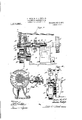
- Fig. 4 is a front elevation of the machine.
- Fig. 5 is an enlarged section on line m
- Fig. 6 is an enlarged section on line e, z, Fig. 1.
- Fig. 7 is an enlarged section uon line 1, y, Fig. 1.
- Fig. 8 is a detail side elevation of one of the driving elements for operating the drill and oscillating the grinder wheel.
- Fig. 9 is a section on line s, s, Fig. 6.
- Fig. 10 is an enlarged section on line o, o, Fig. 4.
- Fig. 11 is a section on line h, h, Fig. 9.
- Fig. 12 is a section on line 0, 0, Fig. 9.
- Fig. 13 is a section on line a, a, Fig. 14.
- Fig. 14 is an enlarged section on line u. u, Fig. 1.
- Fig. 15 is a section on line 7c, 7c, Fig. 14.
- Fig. 16 is a section on line m, m, Fig. 15.
- Fig. 17 is a side elevation ⁇ of a modified form of cam and ⁇ carriage frame connection for oscillating the drill.
- Fig. 18 is a section on line n, n, Fig. 15.
- the machine is provided with a swinging frame upon which is journaled, preferably, two grinding wheels suitably driven, one of which is employed for grinding the cutting edge of the drill.
- the second grinding wheel is a ver'y thin disk, adapted to grind Within the grooves of the drill by a hand operation.
- the grinder supporting ⁇ frame is oscillat-ed continuously during the grinding operation in order that the-entire surface of the grinding wheel can be presented to maintain the same true. This oscillating action is accomplished by pitman means in connection-with the main 55 swinging grind jecting from4 the bearing 60 ing4 against ⁇ a bossformed suitably an oscillating fralne, which frame is provided with meansfor adjusting the same to ,and from the grinding wheel.
- the means illustrated for oscillating said drill supporting frame comprises a cam engaging an abutment or projection mounted on the frame, the said cam being driven from the main drive.
- This oscillating movement of the drill supporting -frame provides a relievingflnish from the cutting edge of the drill rearward.
- 1 represents the main supportin frame.
- -- 2 represents a grinder -whee journal frame pivotally supported nal-blocks 3, see Fig. 4, said b cured to the main frame 1,.
- frame2 is referably set at an angle to the 'horizontal ine of the-drill, as a preferred form of mounting, to obtain the angular cut required for the cuttf edge of the drill.
- ' 7 represents a pulley'fixed to the lspindle for rotating the same and grinder wheels.
- 4 12Y represents a pulleyxed to the which is loosely mounted a 'sleeve land driven from anysource of power.
- shaft 15, seeFigs. 6, 7, and i24 represents a pitman leverengaged with said vdisk at one end, the opposite end being ivotally connected to a strap 25, mounted) justing rod 26 and adapted to be friet-ionally clamped thereto after an adjustment of the screw rod has been made.
- the screw rod 26' has a threaded engagement within a-bore formed in the bearing 2b of theswinging frame 2, said bearihg is provided with a l vertical slit 28, medial? of the screw rod 26,
- the angle of oscillation of frame 2 is constant, but the frame- 2 can be adjusted to and from the drive shaftA by means ofthe adjusting screw 26, thereby enabling the entire 'grinding surface oft-hel grinder wheel 5 to be brought into use.
- I 30 representsv a horizontally adjustabledrill stocksupporting frame slidab e upon ways 31, formed on the main frame 1, see Figs. 4, 10 and 14.
- a sleeve boss projecting from said base frame 30, forming the axis for-the drill oscillating frame 39, which is pivotally mounted to the base plate 30, by means of a stud 40, seated within the sleeve boss 38, see Fig. 5, and maintained in such position by a plate-41, secured to the boss 40, and engag- ,ing with the edge or end of the sleeve boss 38.
- Adjusting the suppo ting frame 30 to and from the rinder wheel changes .the angle of oscillation of the oscillating frame 39, relative to the grinder, in that the axial line of fulcrum to which the drill point is gaged, is changed relatively to the grinder. This adjustment governsthe width of the drill point and its edge. This adjustment also I* provides means for .taking up the wear of thegrinder wheel.
- . represents a universal shaft connection coning drill frame j formed upon nected with the sleeve 46 and the shaft 48, suitably .journaled' within bearings 49, 50, the oscillating frame 39.
- 51 represents a bracket arm. fixed to the base plate 30 and projected upwardly, providing a bearing for the roller 52, see Figs. 1 and 2.
- 53 represents a cam fixed upon the shaft 48, its periphery adapted to engage with the periphery of the roller 52.
- 54 represents a depending arm projecting from'the oscillat- 39, its free end provided with a rod 55, see Fig. 14, said rod engaging with and projecting through a swiveled plug 56, pivotally mounted upon a boss pro jecting from the base plate 30, see Figs.
- 57 represents a coil spring encircling said rod 55 and engaging against said plug for' maintaining said oscillating frame 39 under tension in a direction toward the roller 52,'and in consequence thereof, maintaining the cam 53 in constant 'contact with said roller.
- the oscillating frame willbe swung upon its axis t o and from the roller 52, according to the outline or configuration of said cam 53.
- Figs. 17 and 18 'a modified form of cam and cam engaging mechanism is provided, whereby variable speeds of frame oscillation 1, for securely locking the baseframe 39 is oscil-y can be had, the adjustment from one speed to another being easily and conveniently ac complished.
- the cam 53a in this instance, is of elongated form and of varying diameters, but in which the length of oscillating stroke ofthe frame 39 is constantand not affected by any adjustment made between the cam and roller 52, the adjustment merely changing the 'speed of oscillation upon. a given' rotation of the cam with the roller in a given position from that of a second position.
- the same general cam outline is maintained through the entire width of the cam, but merely changing the circumference travel of the cam according to the position of the engagement therewith.
- the roller 52 is journaled upon a sleeve 58, saidsleeve in turn being fixed to an adjusting rod 59, adjustably mounted upon the bracket arm 51 and adapted to be adjusted in a transverse or horizontal direction to the rotation of the cam.
- a rail 60 is formed upon the base plate 30 and projected upwardly therefrom, upon which rail the swinging frame slides, see Figs. 4 ⁇ and 14, this being provided owing to the peculiar shape of the swingingframe 39.
- the rail 60 may be provided with rollers or other suitable anti-friction means for a free oscillation of the frame 39.
- the swinging frame 39 upon itsvupper surface is provided preferably with a dove-tailed way 61.
- 62 represents a carriage slidably lmounted within said dove-tailed way 61, pro
- 64 represents a drill spindle having a chuck head 65, for clamping the drill thereto, said spindle bein g journaled within the sleeve63 and projecting beyond the same.
- The. spindle 64 is maintained relatively with the sleeve 63, by means of a shoulder formed thereon, engaging the sleeve 63 at the chuck nd, see Fig. 15, and a collar 66 engaging against the opposite end of the sleeve 63, which collar is fixed to the spindle@ 64.
- the chuck end of the spindle is preferably formed by a series of slits with a friction clamping collar 67 screw threaded thereon, provided with the internal peripheral inclined surface adapted to engage with theinclined peripheral-surface of the spindle 64.
- a friction clamping collar 67 screw threaded thereon, provided with the internal peripheral inclined surface adapted to engage with theinclined peripheral-surface of the spindle 64.
- the spindle is rotated by the following instrumentalities:-68 represents gear provided with an elongated sleeve 69,'projecting into a bearing 70, formed upon the oscillating'frame 39, said sleeve and gear b eingsplined to the spindle, permitting adjustment and reciprocating mdveme'nt of the spindle during its rotation, see Fig. 15.
- the following instrumentalities -68 represents gear provided with an elongated sleeve 69,'projecting into a bearing 70, formed upon the oscillating'frame 39, said sleeve and gear b eingsplined to the spindle, permitting adjustment and reciprocating mdveme'nt of the spindle during its rotation, see Fig. 15.
- gear 68 is in mesh with a gear 71, loose upon a stud shaft supported bythe oscillating frame 39, see Fig. l, said gear in turn being in mesh with a gear 72 fixed to the driving shaft 48.
- motion is transmitted from the driving shaft 48, through the 71 and 68 to the drill spindle 64.
- Aninterchangeable system of gearing may be provided between the drive shaft 48 and drill spindle 64, for varying the spindle rotation relatively with the other actuating elements of the head-stock.
- This interchangeability may be accomplished in any ofthe well known ways common in the art of machine tools, but the possible adherent advantages had, are herein desired to be embodied and form a part .of this invention.v
- the carriage 62 is provided with means for reciprocating the same in step movements to and from the grinder Wheel requisite lto provide a lrelieving cut or finish eX- tending from each cutting edge of the drill rearward, in order to move the drill against gears 72,
- one arm of said lever is provided with 'a roller 77, adapted to engage against the cam surface 74, of the cam wheel 73, while the opposite arm of said lever 75, engages against a roller 78, mounted and journaled upon 'the carriage 62.
- 79 represents a .spring interposed between thelugs 80, 81, projecting respectively from theoscillating fra1nel39 and the carriage 62, see Fig. 15, for moving said carriage automatically in one direction or exerting tension upon the lever 75, to maintain the same in contactwith the cam surface .of the cam wheel 73, c thereby moving, upon rotation of the cam, thecarriage to and from the grinding wheel according to the outline of said cam surface.
- cam Vsurface is providedj wheel 86, see Fig. 14.
- the drill is j adjusted and fed to the grinder'for a proper depth of grind manually' and automatically bythe following instrumentalities-82 vrepresents rack teeth, see Figs. 4 and 14, formed on the spindle 63, in m'esh with a rack pinion 83, fixed to the shaft 84, journaled and projected through aY sleeve 85, forming a hub for the worm
- the sleeve 85 is journaled in a bearing 87, formed on the carriage 62.
- 88 represents a hand wheel fixed to the shaft 84, for rotating said shaft and rack pinion 83, for adjusting by hand or feeding the spindle 63 vto and from the grinding wheel.
- the power feed is transmitted to the shaft 84 through the worm illustrated, is adapted to' be frictionally clamped to saidshaft.
- 89 represents a j friction clutch member provided with)an angular periphery adapted to engage with an angular'surface correspondingly provided within the worm wheel 86 into such position
- '91 represents aworm Xed to the shaft 92, see Fig. 13, in mesh with the worm wheel/86.
- Said shaft 92 is journaled in the bearings 93, projecting from the bracket or bearing 87, see Figs. 13 and'14.
- 94 represents a hand wheel fixed to the shaft 92for rotating the same, to provide a slow-hand feed for the spindle when the shaft 84 is clutched tol the worm wheel 86.
- 95 represents a ratchet wheel fixed upon' shaft y92
- 96 represents a 'pawl pivotally mounted upon the lever 97, see Fig.
- the said pawl' having but slight pivotal movement ina direction away from the periphery of the L ratchet wheel 9 5, to permit the same to pass over the teeth of the ratchet wheel upon 'a return stroke, or in other words, for movement of the carriage 62v toward the grindin wheel.
- 98 represents a springl controlled pin exerting tension upon'the pawl 96, for maintaining? the same in contact with the teeth of the ratchet wheel during a feed step.'A
- the pawl lever 97l is pivotally mounted between ears formed upon the support 99, fixed to a rod projected upwardly from the boss 76, see Figs. ⁇ 14, 15, and 16.
- a the carriage 62 ismoved toward the grinder wheel by the cam 73 and lever 75, the pawl 96 will engage with the teeth of the ratchet y wheel 95, and rotate the same a given degree or until the pawl becomes disengaged from the teeth of the ratchet'wheel 95, in
- the following instrumentalities 'are provided z-100 represents, see ⁇ -Figs. 14 and 15, a tripdog'ladjustably secured within the dove-tailed groove 101, formed within the spindle sleeve 63, said dog being adapted to be adjusted to govern the amount of spindle feed of the spindle relative to the grinder wheel, whereby a predetermined length of spindle feed can be had.
- 102 represents a trip engaging rod fixed to and projecting from a lever 103, pivotally supported upon a'brac'ket arm 104, projected from the support 99.
- the lever 103 is projected upwardly,.provided with a lock-plate 105, adapted to engage beneath the lock-plate 106, xed to the pawl lever 97, see Fig. 15, to maintain thepawl 96 in a position to .engage with the teeth of the ratchet wheel 95 on a forward movement of the spindle carriage 62.
- 108 represents ra spring-controlled pin supported within the support 99, adapted to engage and exert tension against the lever 103, when the pawl lever 97 has been swung to its automatic spindle feed position, to automatically re-' turn the lock plate 105 beneath the lock plate 106, on the pawl lever 97.
- 109, 110 represent hand holds formed upon and projected from the levers 103 and 97 respec ⁇ tively, for manipulating said lever by hand, for' manually disengaging the automatic feed or vice versa.
- 111 represents a stop pin adjustably mounted in the support 99, to limit the movement of the trip lever 103.
- 112 represents a drill supporting standard mounted upon the oscillating frame 39, and
- 113 represents a drill support provided with cutting edges 4 of the a V-groove, within which the .drill seats, said support being adjustably mounted upon the standard 112, thereby forming a rigid support for the free ends of the drill and preventing or disturbing its axial alinement with. the spindle. It is obvious, construction of the support may be variously modified to produce the same result.
- a hand wheel fixed to thel 114 represents shaft 48, whereby the various actuation and rotation of the drill spindle can be had in order to adjust and mount the drill within the spindle.
- angle of oscillation can be gaged by adjusting the cam roller 53, as well as to p rovide a slow oscillation to give a more or lieving or tapering cut.
- a main' frame a grinder wheel rotatively mounted upon said main frame, an oscillating drill stock supporting frame vmounted on said main frame, means for oscillating said frame,
- a drill grinding machine a main frame, an oscillating drill stock supporting frame, means for oscillating said frame, a grinder wheel angularly disposed relative thereto, means for oscillating said grinder wheel, means for adjusting said oscillating frame to and from the grinder wheel for governing the angle of oscillation relative to the grinder wheel, a drill spindle supporting carriage slidably mbunted upon said oscillating frame, means for reciprocating said carriage, a drill spindle mounted on said carriage, means for rotating said drill spindle, and means for horizontally feeding said drill spindle independent of its rotation, whereby a drill is fed to and from the work at step periods during a given rotation of in a continuous arc of movethe drill and rinder, providing ment to the action of the a relieving finish V1n rear o of the drill.
- each cutting edge means for oscillating the Alng surface into means for oscillatin" the spindle to grind the drill in the arc o a circle, andmeans for rocking' the grinder to bring the entire grinding surface into actionA on the drill point.
- a machine for grinding a twist drill a rotary grinder, a drill supporting'spindle, means for rotating the spindle in the opposite direction from the grinder, means for reciprocating the spindle longitudinally in time movement to successively present the cutting edges of the drill to the grinder, means for oscillating the spindle to grind the drill in the arc of a circle, and means ,for rocking the grinder to bring its entire grind-v action on thedrill point,4 and means for longitudinally feeding the drill to the grinder.
- a machine for grinding a'twist drill a rotary grinder, a drill supporting spindle, means for .rotating the spindle in the opposite ,direction from ⁇ the grinder, means for reciprocating the spindle longitudinally in time movement to successively present the cutting edges of the drill lto the grinder, spindle to grind the drillv in the arc of a circle, and means for rocking thegrinder tobring its entire grinding surface into action'on the drill point, means for longitudinally feeding the drill to the grinder, and means for changing the angle of s indle oscillation. j 6.
- a rotary grinder In a machine for grinding a twist drill', a rotary grinder, a drill supporting spindle, means for rotating the spindle, means" for reciprocating the spindle longitudinally in time movements'to successively present the cutting' edges of the drill to the grinder, means for oscillating the spindle, and means for changing the action of oscillation. 7.- In a machine of the class described, a
- rotar grinder means for oscillating s aid y* cuttingsedges rin er, a drill supporting.
- spindle means or reciprocating the spindle longitudinally, means for rotating the spindle relative to its reciprocation ⁇ to successively present the of the drill to the grinder in time movements during a given spindle 'rotation', means for oscillating the spindle to provide a -relieving cut in ⁇ ,-'rear of each cutting edge, means for feeding the spindle to and from the grinder, and a single driving shaft in connection with various spmdle operating meansv and grinder osclllatmg meansprovided with intermediate iexible connections to automatically accommodaItejitself for the spindle actuations.
- vdriving sha ,latter 1n relative ratio means for rotating the spindle, means for v reciprocating the spindle longitudinallyin' ofl a given rotation ofthe spindle', means for Aoscillating the spindle, and means for feeding the spindle independent of spindle reciprocation with' the feeding means automatically actuated. .through the spindle reciprocation.
- a a drill'supporting spindle means for rotating the spindle, means for reciprocating the spindle longitudinally in ⁇ time movements of a given rotation of the spindle, means for oscillating the spindle, means for manually feeding the spindle to the grinder, means for disengaglng said manual forward feed, and means to provide a quick reverse feed of the spindle upon release of said forward ⁇ -manual feed.
- a rotary grinder In a machine of the class described, a rotary grinder, a drill supporting spindle, means for rotating said -spindle,means forl reciprocating said spindle to serially present initially each cutting edge to the action of the grinder, means for oscillating the spindle to grind the drill tapering from, each cutting edge, means for feeding the spindle to the'grinderfautomatically and independent of the spindle reciprocation, and means for automatically disengaging said spindle feed at a predetermined point of spindle feed.
- a base'frame a rotarv grinder mountedtlereon, a drill stock supporting frame adjustably mountedI on said main frame, means for adjusting the same thereon to and from I the grinder, an oscillatin frame pivotally supported upon said ⁇ sli e frame, a drill spindle journaled upon said oscillating frame, a main driving shaft journaled upon.
- main drivin shaft connections between the and spindle, for rotating the roportionatel to the number 4of grooves in t e drill, and means vfor reciprocating said spindle in successive from the grinder independent ofkk its rotary grinder', an oscillating frame, mov v able to and from the grinder to change the degree of oscillation relative thereto, means for locking the same in its adjusted position, 50 a main driving shaft journaled upon said oscillating frame, a carriage movable upon said frame,connections between said driving shaft and carriage for reciprocating the lat' movements ,upon each rotation of the spinl dle ro ortionate to the number of grooves in t e rill, means for oscillating said spindle to rind the work tapering, the number of ose' lations proportionate to the number of grooves in the drill, means for'feedin'g 'the spindle to the grinder automatically independent of the reciprocatory action 'of said spindle, and means for disconnecting said 10
- a rotary grinder In a machine of the'class described, a rotary grinder, a drill supporting spindle, means for rotating said spindle, a main driving shaft journaled parallel with said spindle, means in connection with said shaft 75 for reciprocating said spindle in a ratio proortionate to the number of grooves inthe 15; ⁇
- a rill means foros'cillating said spindle to rotary grinder, an oscillating frame, means grind the drill tapering from each cutting for adjusting the same relative to the grinder, edge, means for c anging the degree of os- 80 a carriage movable upon saidframe, means cillation, means for changing the Speedo for reciprocating ⁇ the same thereon, a spinoscillation relative tothe rotation of the main dle sleeve mounted within said carriage, shaft without effecting the degree of oscillaand means forl feeding said sleeve to and tion.
Description
A. MILL, Sn. L A. MILL, JR. MACHINE FOR GRINDING DRILLS. APPLIGATION FILED ocmw, 1910.
Patented Feb.6,1912;
6 SHEETS-SHEET 1.
Gimme/134- A. MILL, Sn; & A. MILL, Jn.
MACHINE P011 GRINDING DnILLs.
APPLICATION FILED 00T.10, 1910.
Patented Feb. 6, 1912.
6 SHEETS-SHEET 2.
A. MILL, SR. & A. MILL, Jn.
MACHINE FOR GRINDNG DRILLS.
APPLOATION FILED oofl 1o, 1910.
latnted Feb. 6
6 SHEETS-SHEET 3.
Wwf/@Mm A. MILL, SR. al A. MILL, JB. MAGHUSIE FOR GRINDING DRILLS. l APPLICATION FILED 00T.10, 1910. LmgL Patented Feb.6,1912.
6 SHEETS-SHEET 4,
A. MILL, Sa. & A. MILL, JR. MACHINE POR GRINDING DRLLS.
A. MILL, Sn. & A. MILL, Je. MAGHINE Foe GRINDING DRILLS. APPLIOATIQN FILED OOTJO, 1910. 1 901 @9891 Patented Feb. 6, 1912.
6 'SHEETS-SHEET 6.
www,
llllll.. .ull-... m.
lil
aan saar-Es rAraNzfr carica.
ANTON MILL, SR., AND ANTON MILL, JR., OF CINCINNATI, OHIO, ASSIGNORS T HEINRICH HEINE, OF CHICAGO, ILLINOIS.
MACHINE FOR' GRINDING DRILLS.
To all whom z5 may concern.'
Be it known that we, ANTON MILL, Sr., and ANTON MILL, J r., citizens of the United States, both residing at Cincinnati, 4in the county of Hamilton and State of Ohio, have invented certain new and useful Improvements in Machines for Grinding Drills, of which the following is a specification.
Our invention relates to a machine for` grinding drills and the like metal cutting tools.
One of the objects of the invention is to provide means for rotatively presenting a drill to the action of an oppositely rotating grinding wheel.
Another ob ect of our invention is to provide means for rotating and oscillating a drill in an arc relatively to a grinding wheel, for providing the drill with a proper relieving finish in rear or each cutting edge.
Another object of our invention is to provide a drill grinding machine, with means forautomatically reciprocating the drill to and from the grinding wheel in time movements for serial grinding actions, commencing at the cutting edge and grinding rearward therefrom, to enable a proper relieving finish to be made. V
Another object of our inventionis to provide a drill grinding machine, with means for oscillating the grinder relatively to the drill for constantly presenting a new cutting surface of the grinder to the drill.
Another object of our invention is to p rovide means Afor changing the relative rotation bet-Ween the drill and drill reciprocating mechanism for varying the number of reciprccations during a given revolution of the drill according to the number of cut-ting edges the drill may be provided with..
Another object of our invention is to provide means for manually or automatically feeding the drill to the grinder independent of drill reciprocation.
Another object'ofour invention is to pro-- vide means for changing the angle of oscillationvv of drill relative to the'grinder cutting edge.
Another 'object of our inventionis to provide means for automatically -discontinuing the automatic feed of the drill to the grinder.
Specification of Letters Patent.
Patented Feb. 6, 1912.
Application filed October 10, 1910. Serial No. 586,299.
Another object of our invention is to pro'- videmeans of adjustment for the grinder wheel relatively to the work to enable the presentation of the entire grinding surface of the grinder wheel to the Work.
Another object of our invention is to provide means for supporting the free or cutting end of the drill or work.
Another object of our invention is to provide means for increasing or decreasing the act-ion of oscillation of the drill.
Various 'other features of our invention are more fully' set forth in the description of the accompanying drawings, forming a part of this specification, in which- Figure 1 is a top view of the machine.
Fig. Q is a section on line c, c, Fig. 1. Fig. 3 is a section on line r, 7^,.Fig. 1. Fig. 4 is a front elevation of the machine. Fig. 5 is an enlarged section on line m, Fig.v 4. Fig. 6 is an enlarged section on line e, z, Fig. 1. Fig. 7 is an enlarged section uon line 1, y, Fig. 1. Fig. 8 is a detail side elevation of one of the driving elements for operating the drill and oscillating the grinder wheel. Fig. 9 is a section on line s, s, Fig. 6. Fig. 10 is an enlarged section on line o, o, Fig. 4. Fig. 11 is a section on line h, h, Fig. 9. Fig. 12 is a section on line 0, 0, Fig. 9. Fig. 13 is a section on line a, a, Fig. 14. Fig. 14 is an enlarged section on line u. u, Fig. 1. Fig. 15 is a section on line 7c, 7c, Fig. 14. Fig. 16 is a section on line m, m, Fig. 15. Fig. 17 is a side elevation `of a modified form of cam and` carriage frame connection for oscillating the drill. Fig. 18 is a section on line n, n, Fig. 15.
As illustrated, the machine is provided with a swinging frame upon which is journaled, preferably, two grinding wheels suitably driven, one of which is employed for grinding the cutting edge of the drill. The second grinding wheel is a ver'y thin disk, adapted to grind Within the grooves of the drill by a hand operation. The grinder supporting` frame is oscillat-ed continuously during the grinding operation in order that the-entire surface of the grinding wheel can be presented to maintain the same true. This oscillating action is accomplished by pitman means in connection-with the main 55 swinging grind jecting from4 the bearing 60 ing4 against `a bossformed suitably an oscillating fralne, which frame is provided with meansfor adjusting the same to ,and from the grinding wheel. The means illustrated for oscillating said drill supporting frame comprises a cam engaging an abutment or projection mounted on the frame, the said cam being driven from the main drive. This oscillating movement of the drill supporting -frame provides a relievingflnish from the cutting edge of the drill rearward.l
Drills commonly' areA provided with two Jcutting edges and therefore it is desirable to have a relieving cut or finish extended rearward from each cutting edge. This necessitates that the drill bemoved to and from the grinder to properly grind the same, Vand this v1s accomplished automatically by means of a swinging vlever engaging the drill spindle 25 at one end, the opposlteend engagingl agalnst a cam driven from the main sourceA of power. If, however, thedrill is provided with three or more cutting edges, a chan e t of rela-tive actuation and rotation must e made, 'and this is accomplished in providing interchangeable gearsfor driving the drill spindle.
' With our machine, we are able'to'grind a drill geometrically correct and adjustable to e take the general standard sizes of drills.'
1 represents the main supportin frame.
-- 2 represents a grinder -whee journal frame pivotally supported nal-blocks 3, see Fig. 4, said b cured to the main frame 1,.
frame2 is referably set at an angle to the 'horizontal ine of the-drill, as a preferred form of mounting, to obtain the angular cut required for the cuttf edge of the drill.
4 represents a grin er spindle journaled in 'bearings 2, 2b, formed upon 'the frame 2, and uponwhich spindle the main grinder wheel 5 and the supplemental grinder wheel 6 are mounted in any well known or usual.
manner.'
' 7 represents a pulley'fixed to the lspindle for rotating the same and grinder wheels.
8 represents a bearing frame. fixed to the `main frame-.1, oppositely disposed tothe er frame 2, and preferably parallel therewith, see Fi s. 1, 6,- 7, 8 and 9.
9 represents a stud sha ixed to and proframe 8, upon sleeve 10, bearon the frame 8 at one end, and againstthe collar 11' or flange formed on the stud shaft 9, for 'main -tainmg 'the sleeve 10 in position. 4 12Y represents a pulleyxed to the which is loosely mounted a 'sleeve land driven from anysource of power.
19 represents -a yoke lever pivotally supported between the ears 20, projecting from the housing 17, the yoked 'end of said lever straddling said clutch'sleeve 18, and provided with crescents pivotally mounted upon the limbs of said yoke lever, and engaging into the peripheral groove 21 formed upon the clutch sleeve 18. f
22 represents a rod xed to the lever 19 for actuating the same.
23'represents an eccentric disklixed to the.
upon an adsee Fig. 7, and a set screw 29 at right 'anglesY thereto, for frictionally clamping the screw rod 26 in its 4adjusted position. Thus, as the driving shaft 15 is rotated, oscillating movement will be imparted to the grinder frame 2, through the eccentric, disk 23,\fpitman 24, strap and screw rod connections`with the frame 2. i
As shown in the drawings, the angle of oscillation of frame 2 is constant, but the frame- 2 can be adjusted to and from the drive shaftA by means ofthe adjusting screw 26, thereby enabling the entire 'grinding surface oft-hel grinder wheel 5 to be brought into use. I 30 representsv a horizontally adjustabledrill stocksupporting frame slidab e upon ways 31, formed on the main frame 1, see Figs. 4, 10 and 14. I
32 represents a bearing bracket, see Fig. 10,`ixed to the frame '1, provided with the bearing sleeve 33, within which is journaled a shaft 34, provided with a pinion 35, engaging with a rack plate 36, lixedto the ase plate 30.
37 represents a hand wheel' fixed to the shaft 34, the rotation of which transmits lmotion tothe rack pinion 35, for horizontally adjusting the drill stock base plate 30',
to and from t sents a sleeve boss projecting from said base frame 30, forming the axis for-the drill oscillating frame 39, which is pivotally mounted to the base plate 30, by means of a stud 40, seated within the sleeve boss 38, see Fig. 5, and maintained in such position by a plate-41, secured to the boss 40, and engag- ,ing with the edge or end of the sleeve boss 38.
Adjusting the suppo ting frame 30 to and from the rinder wheel changes .the angle of oscillation of the oscillating frame 39, relative to the grinder, in that the axial line of fulcrum to which the drill point is gaged, is changed relatively to the grinder. This adjustment governsthe width of the drill point and its edge. This adjustment also I* provides means for .taking up the wear of thegrinder wheel.
42 re resents a set nut, see Figs. l2 and 14, havmg a threaded engagement with the base plate 30, adapted to clamp the gib-plate 43 against one of the slide-ways 31, of the main frame plate 3() in any adjusted The drill oscillating lated by means of the following instrumentalities:44 represents a universal shaft connection fixed to the shaft 15, see Figs. 1 and 6,'and`to the slide 'shaft 45, being preferably square in cross-section and loosely projecting into a square board sleeve 46, forming compensating means for the Idriving shaft, in making an adjustment of the base plate 30 upon the main frame 1. 47
position.
. represents a universal shaft connection coning drill frame j formed upon nected with the sleeve 46 and the shaft 48, suitably .journaled' within bearings 49, 50, the oscillating frame 39. 51 represents a bracket arm. fixed to the base plate 30 and projected upwardly, providing a bearing for the roller 52, see Figs. 1 and 2. 53 represents a cam fixed upon the shaft 48, its periphery adapted to engage with the periphery of the roller 52. 54 represents a depending arm projecting from'the oscillat- 39, its free end provided with a rod 55, see Fig. 14, said rod engaging with and projecting through a swiveled plug 56, pivotally mounted upon a boss pro jecting from the base plate 30, see Figs. 2, 4, and 14. 57 represents a coil spring encircling said rod 55 and engaging against said plug for' maintaining said oscillating frame 39 under tension in a direction toward the roller 52,'and in consequence thereof, maintaining the cam 53 in constant 'contact with said roller. Thus, upon the rotation of said cam, the oscillating frame willbe swung upon its axis t o and from the roller 52, according to the outline or configuration of said cam 53.
In Figs. 17 and 18 'a modified form of cam and cam engaging mechanism is provided, whereby variable speeds of frame oscillation 1, for securely locking the baseframe 39 is oscil-y can be had, the adjustment from one speed to another being easily and conveniently ac complished. The cam 53a, in this instance, is of elongated form and of varying diameters, but in which the length of oscillating stroke ofthe frame 39 is constantand not affected by any adjustment made between the cam and roller 52, the adjustment merely changing the 'speed of oscillation upon. a given' rotation of the cam with the roller in a given position from that of a second position. The same general cam outline is maintained through the entire width of the cam, but merely changing the circumference travel of the cam according to the position of the engagement therewith. In this instance, the roller 52 is journaled upon a sleeve 58, saidsleeve in turn being fixed to an adjusting rod 59, adjustably mounted upon the bracket arm 51 and adapted to be adjusted in a transverse or horizontal direction to the rotation of the cam. By this means, varying degrees of relieving finish can be had, as the larger sized drills require a greater degree of relieving ct or finish than the smaller sized drillsr For rigidity of the swinging plate 39, a rail 60 is formed upon the base plate 30 and projected upwardly therefrom, upon which rail the swinging frame slides, see Figs. 4`and 14, this being provided owing to the peculiar shape of the swingingframe 39. The rail 60 may be provided with rollers or other suitable anti-friction means for a free oscillation of the frame 39.? It is obvious, however, that the design and construction of the various members, forming what may be termed lthe head-stock of the grinder, may be variously modified without departing from the features ofA our invention. The swinging frame 39 upon itsvupper surface is provided preferably with a dove-tailed way 61. 62 represents a carriage slidably lmounted within said dove-tailed way 61, pro
vided with a bore through which the spindle sleeve 63 projects and is fed. 64 represents a drill spindle having a chuck head 65, for clamping the drill thereto, said spindle bein g journaled within the sleeve63 and projecting beyond the same. The. spindle 64 is maintained relatively with the sleeve 63, by means of a shoulder formed thereon, engaging the sleeve 63 at the chuck nd, see Fig. 15, and a collar 66 engaging against the opposite end of the sleeve 63, which collar is fixed to the spindle@ 64. The chuck end of the spindle is preferably formed by a series of slits with a friction clamping collar 67 screw threaded thereon, provided with the internal peripheral inclined surface adapted to engage with theinclined peripheral-surface of the spindle 64. Thus, as the collar 67 is fed upon the spindle after the drill has been inserted within the spindle, the same will be frictionally clamped thereto. 1t is obvious,howeve/r, that the spindle maybe i provided with any form of chuck of commercial type or otherwise.
The spindle is rotated by the following instrumentalities:-68 represents gear provided with an elongated sleeve 69,'projecting into a bearing 70, formed upon the oscillating'frame 39, said sleeve and gear b eingsplined to the spindle, permitting adjustment and reciprocating mdveme'nt of the spindle during its rotation, see Fig. 15. The
gear 68 is in mesh with a gear 71, loose upon a stud shaft supported bythe oscillating frame 39, see Fig. l, said gear in turn being in mesh with a gear 72 fixed to the driving shaft 48. Thus, motion is transmitted from the driving shaft 48, through the 71 and 68 to the drill spindle 64.
Aninterchangeable system of gearing may be provided between the drive shaft 48 and drill spindle 64, for varying the spindle rotation relatively with the other actuating elements of the head-stock. vThis interchangeability may be accomplished in any ofthe well known ways common in the art of machine tools, but the possible adherent advantages had, are herein desired to be embodied and form a part .of this invention.v The carriage 62 is provided with means for reciprocating the same in step movements to and from the grinder Wheel requisite lto provide a lrelieving cut or finish eX- tending from each cutting edge of the drill rearward, in order to move the drill against gears 72,
35 the grinding wheel during the oscillation in the one direction of the frame 39 and autof matically and quickly returning to normal position for a proper presentation of the second cutting edge of the drill l to thel 40 grinder. This is accomplished by means of the followingv instrumentalities 73 represents a cam wheel, see Figs. 1, 13 and 14, providedwith a cam surface 74, upon one side thereof, the cam wheel 73 being -xed to the drive shaft 48. 75 represents a lever pivotally mounted upon a boss 7 6, projected upwardly from the oscillating frame 39, see Fig. 14, one arm of said lever is provided with 'a roller 77, adapted to engage against the cam surface 74, of the cam wheel 73, while the opposite arm of said lever 75, engages against a roller 78, mounted and journaled upon 'the carriage 62. 79 represents a .spring interposed between thelugs 80, 81, projecting respectively from theoscillating fra1nel39 and the carriage 62, see Fig. 15, for moving said carriage automatically in one direction or exerting tension upon the lever 75, to maintain the same in contactwith the cam surface .of the cam wheel 73, c thereby moving, upon rotation of the cam, thecarriage to and from the grinding wheel according to the outline of said cam surface.
As illustrated, the cam Vsurface is providedj wheel 86, see Fig. 14.
and clamped mate form to permit of the desired carriage movement to present the drill to the grinder initially from1 its cutting edge `and withdrawing the same therefrom quickly, to en-v ablethejproper presentation of the second cutting edge to the action of the grinder. t
The drill is j adjusted and fed to the grinder'for a proper depth of grind manually' and automatically bythe following instrumentalities-82 vrepresents rack teeth, see Figs. 4 and 14, formed on the spindle 63, in m'esh with a rack pinion 83, fixed to the shaft 84, journaled and projected through aY sleeve 85, forming a hub for the worm The sleeve 85 is journaled in a bearing 87, formed on the carriage 62. 88 represents a hand wheel fixed to the shaft 84, for rotating said shaft and rack pinion 83, for adjusting by hand or feeding the spindle 63 vto and from the grinding wheel. The power feed is transmitted to the shaft 84 through the worm illustrated, is adapted to' be frictionally clamped to saidshaft. 89 represents a j friction clutch member provided with)an angular periphery adapted to engage with an angular'surface correspondingly provided within the worm wheel 86 into such position Aby meansof anut 90screw threaded upon the shaft84, 95
sis
see Fig. 14, whichwill lock the pinion 83,
The pawl lever 97l is pivotally mounted between ears formed upon the support 99, fixed to a rod projected upwardly from the boss 76, see Figs.`14, 15, and 16. Thus, a the carriage 62 ismoved toward the grinder wheel by the cam 73 and lever 75, the pawl 96 will engage with the teeth of the ratchet y wheel 95, and rotate the same a given degree or until the pawl becomes disengaged from the teeth of the ratchet'wheel 95, in
moving beyond the same. .This action will 130..
- rotate the feed shaft 92, worm 91, wormj,
ward to bring the tripping dog 100 into endrill and its spindle can wheel 86, shaft 34, rack-pimon 83 and spindle-sleeve 63, provided, however, that the worm-wheel 86 is frictionally clamped or in driving connection withl the shaft 84, in which instance, an automatic feed of the be had upon each forward reciprocation of the spindle carriage 62. v
In order to automatically throw' out or discontinue the automatic feed of the drill spindle, the following instrumentalities 'are provided z-100 represents, see`-Figs. 14 and 15, a tripdog'ladjustably secured within the dove-tailed groove 101, formed within the spindle sleeve 63, said dog being adapted to be adjusted to govern the amount of spindle feed of the spindle relative to the grinder wheel, whereby a predetermined length of spindle feed can be had. 102 represents a trip engaging rod fixed to and projecting from a lever 103, pivotally supported upon a'brac'ket arm 104, projected from the support 99. The trip rod 102 projecting from said lever ,and into the path yof dog travel, in order to be engaged thereby to actuate the lever 1'03. The lever 103 is projected upwardly,.provided with a lock-plate 105, adapted to engage beneath the lock-plate 106, xed to the pawl lever 97, see Fig. 15, to maintain thepawl 96 in a position to .engage with the teeth of the ratchet wheel 95 on a forward movement of the spindle carriage 62. When the spindle sleeve 63, carrying the spindle 64, has been fed forgagement with the rod 102, it will rock the lever 103, disengagin the lock-plate 105, carried by said lever rom beneath the lock plate 106 on lever- 97, permitting said lever to dro sufficiently to'disengage the pawl 96 from lts tooth engagement with the ratchet wheel 95. y107 represents a spring controlled pin mountedA in the support 99, adapted to engage the pawl lever 97, and exert upward tension thereon to swing the pawl 96 away from the ratchet wheel, when the lever 103 has been4 tripped. 108 represents ra spring-controlled pin supported within the support 99, adapted to engage and exert tension against the lever 103, when the pawl lever 97 has been swung to its automatic spindle feed position, to automatically re-' turn the lock plate 105 beneath the lock plate 106, on the pawl lever 97. 109, 110 represent hand holds formed upon and projected from the levers 103 and 97 respec` tively, for manipulating said lever by hand, for' manually disengaging the automatic feed or vice versa. 111 represents a stop pin adjustably mounted in the support 99, to limit the movement of the trip lever 103. 112 represents a drill supporting standard mounted upon the oscillating frame 39, and
113 represents a drill support provided with cutting edges 4 of the a V-groove, within which the .drill seats, said support being adjustably mounted upon the standard 112, thereby forming a rigid support for the free ends of the drill and preventing or disturbing its axial alinement with. the spindle. It is obvious, construction of the support may be variously modified to produce the same result.
a hand wheel fixed to thel 114 represents shaft 48, whereby the various actuation and rotation of the drill spindle can be had in order to adjust and mount the drill within the spindle.
It is obvious that the angle of oscillation can be gaged by adjusting the cam roller 53, as well as to p rovide a slow oscillation to give a more or lieving or tapering cut.
Having described vour claim zless reinvention, we
downward strains uponthe drill fast or.
however, that the 1. In a drill grinding machine, a main' frame, a grinder wheel rotatively mounted upon said main frame, an oscillating drill stock supporting frame vmounted on said main frame, means for oscillating said frame,
means for adjusting said frame to and from to change its degree of oscilla-- the grinder, tion relatively to the grinder, a drill spindle supported upon said oscillating frame with means for manually and automatically feeding the same to the grinder wheel, means for rotating said spindle, and means for reciprocating said spindle in time movements to and from the grinder wheel relative to the number ,of cutting edges that a drill is provided'with in a given rotation of the drill.
2. In a drill grinding machine, a main frame, an oscillating drill stock supporting frame, means for oscillating said frame, a grinder wheel angularly disposed relative thereto, means for oscillating said grinder wheel, means for adjusting said oscillating frame to and from the grinder wheel for governing the angle of oscillation relative to the grinder wheel, a drill spindle supporting carriage slidably mbunted upon said oscillating frame, means for reciprocating said carriage, a drill spindle mounted on said carriage, means for rotating said drill spindle, and means for horizontally feeding said drill spindle independent of its rotation, whereby a drill is fed to and from the work at step periods during a given rotation of in a continuous arc of movethe drill and rinder, providing ment to the action of the a relieving finish V1n rear o of the drill.
. 3. In a machineforlgrindingfa twist drill.,
drill to the/grinder,
each cutting edge means for oscillating the Alng surface into means for oscillatin" the spindle to grind the drill in the arc o a circle, andmeans for rocking' the grinder to bring the entire grinding surface into actionA on the drill point. 4. In a machine for grinding a twist drill, a rotary grinder, a drill supporting'spindle, means for rotating the spindle in the opposite direction from the grinder, means for reciprocating the spindle longitudinally in time movement to successively present the cutting edges of the drill to the grinder, means for oscillating the spindle to grind the drill in the arc of a circle, and means ,for rocking the grinder to bring its entire grind-v action on thedrill point,4 and means for longitudinally feeding the drill to the grinder.
l 5. In a machine for grinding a'twist drill, a rotary grinder, a drill supporting spindle, means for .rotating the spindle in the opposite ,direction from`the grinder, means for reciprocating the spindle longitudinally in time movement to successively present the cutting edges of the drill lto the grinder, spindle to grind the drillv in the arc of a circle, and means for rocking thegrinder tobring its entire grinding surface into action'on the drill point, means for longitudinally feeding the drill to the grinder, and means for changing the angle of s indle oscillation. j 6. In a machine for grinding a twist drill', a rotary grinder, a drill supporting spindle, means for rotating the spindle, means" for reciprocating the spindle longitudinally in time movements'to successively present the cutting' edges of the drill to the grinder, means for oscillating the spindle, and means for changing the action of oscillation. 7.- In a machine of the class described, a
rotar grinder, means for oscillating s aid y* cuttingsedges rin er, a drill supporting. spindle, means or reciprocating the spindle longitudinally, means for rotating the spindle relative to its reciprocation `to successively present the of the drill to the grinder in time movements during a given spindle 'rotation', means for oscillating the spindle to provide a -relieving cut in` ,-'rear of each cutting edge, means for feeding the spindle to and from the grinder, and a single driving shaft in connection with various spmdle operating meansv and grinder osclllatmg meansprovided with intermediate iexible connections to automatically accommodaItejitself for the spindle actuations.
n a machine of the class described, a
s rotary` inder, a drill supporting spindle,
means or rotating said spmdle, meanscfor reciprocating said .spindle intime move- -ments to successively present the cutting edges of the drill to the grinder, means for oscillatingl the spindle to rind the work tapering, -means for feeding the spindle to time movement y rotary grinder,
vdriving sha ,latter 1n relative ratio means for rotating the spindle, means for v reciprocating the spindle longitudinallyin' ofl a given rotation ofthe spindle', means for Aoscillating the spindle, and means for feeding the spindle independent of spindle reciprocation with' the feeding means automatically actuated. .through the spindle reciprocation.-
. l0. In a machine of the class described, a a drill'supporting spindle, means for rotating the spindle, means for reciprocating the spindle longitudinally in `time movements of a given rotation of the spindle, means for oscillating the spindle, means for manually feeding the spindle to the grinder, means for disengaglng said manual forward feed, and means to provide a quick reverse feed of the spindle upon release of said forward `-manual feed. l
11. In a machine of the class described, a rotary grinder, a drill supporting spindle, means for rotating said -spindle,means forl reciprocating said spindle to serially present initially each cutting edge to the action of the grinder, means for oscillating the spindle to grind the drill tapering from, each cutting edge, means for feeding the spindle to the'grinderfautomatically and independent of the spindle reciprocation, and means for automatically disengaging said spindle feed at a predetermined point of spindle feed..
12. In a machine of the class described, a base'frame, a rotarv grinder mountedtlereon, a drill stock supporting frame adjustably mountedI on said main frame, means for adjusting the same thereon to and from I the grinder, an oscillatin frame pivotally supported upon said `sli e frame, a drill spindle journaled upon said oscillating frame, a main driving shaft journaled upon.
said oscillating vframe parallel with said drill spindle, transmission mechanismintermediate of said shaft and spindle for rotatin said spindle, means for reciprocating sald drill spindle in ,operative connection y with said main driving shaft, for reciprocating said s indle in each rotation of the spindle with fiile. numberof reciprocating movements overned by the number of grooves in the dri l, and means for feeding sa1d spindle to' and reciprocation or rotation. A
13. .In a machine of the class described, a
rotary grinder, a drill supporting spindle, a
main drivin shaft, connections between the and spindle, for rotating the roportionatel to the number 4of grooves in t e drill, and means vfor reciprocating said spindle in successive from the grinder independent ofkk its rotary grinder', an oscillating frame, mov v able to and from the grinder to change the degree of oscillation relative thereto, means for locking the same in its adjusted position, 50 a main driving shaft journaled upon said oscillating frame, a carriage movable upon said frame,connections between said driving shaft and carriage for reciprocating the lat' movements ,upon each rotation of the spinl dle ro ortionate to the number of grooves in t e rill, means for oscillating said spindle to rind the work tapering, the number of ose' lations proportionate to the number of grooves in the drill, means for'feedin'g 'the spindle to the grinder automatically independent of the reciprocatory action 'of said spindle, and means for disconnecting said 10 automatic feed atI any point for manual manipulation. A
- 14. In a machine of the class described, a
rotary grinder, a drill supporting spindle, a
'main driving shaft, connections between the driving shaft and spindle, for rotating the latter in relative ratio proportionate to the number of grooves in the drill, and means for reciprocating said spindle in successivel movements upon each rotation of the spindle proportionate to the number of grooves in the drill, means for oscillating said spindle,
I to grind the work tapering, the number of oscillations proportionate to the number of grooves in the drill, means for feeding the spindle to the grinder `automatically independent of the reciprocatory action of said spindle, means for automatically discontinuing said feed after a predetermined travel thereof, and means for disconnecting said automatic feed at Aany point for manual manipulation.
tionate to the number of rooves in the drill 'for each rotation ther-eo a spindle sleeve mounted within the carriage movable therewith, and independently adjustable therein to feed the sleeve to and from said car 60 riage, feeding mechanism therefor, manually or automatic, each independent of the other, said automatic feed operative through the reciprocation of the carriage, a drill spindle rotatively mounted within the sleeve and 65 transversely fed therewith, connections between said main driving shaft and spindle for rotating the latterin a relative rotation proportionate to the numberl of grooves in the drill.` u
17. In a machine of the'class described, a rotary grinder, a drill supporting spindle, means for rotating said spindle, a main driving shaft journaled parallel with said spindle, means in connection with said shaft 75 for reciprocating said spindle in a ratio proortionate to the number of grooves inthe 15;` In al machine of the class described, a rill, means foros'cillating said spindle to rotary grinder, an oscillating frame, means grind the drill tapering from each cutting for adjusting the same relative to the grinder, edge, means for c anging the degree of os- 80 a carriage movable upon saidframe, means cillation, means for changing the Speedo for reciprocating `the same thereon, a spinoscillation relative tothe rotation of the main dle sleeve mounted within said carriage, shaft without effecting the degree of oscillaand means forl feeding said sleeve to and tion. from the grinder independent of carriage In testimony whereof, we have hereunto 85 40 reciprocation, a drill. spindle rotatively set our hands. mounted within said sleeve, and transversely ANTON MILL SR movable therewith, means for revolving said ANTON MILL JR' spindle, and means for oscillating said frame, the number of oscillations proportionate to v'Witnesses: the number of grooves in the drill. CLARENCE B. FOSTER,
16. In a machine of the class described, a Louisa BECK.
ter, the number of reciprocations .propor- 55
Priority Applications (1)
| Application Number | Priority Date | Filing Date | Title |
|---|---|---|---|
| US58629910A US1016891A (en) | 1910-10-10 | 1910-10-10 | Machine for grinding drills. |
Applications Claiming Priority (1)
| Application Number | Priority Date | Filing Date | Title |
|---|---|---|---|
| US58629910A US1016891A (en) | 1910-10-10 | 1910-10-10 | Machine for grinding drills. |
Publications (1)
| Publication Number | Publication Date |
|---|---|
| US1016891A true US1016891A (en) | 1912-02-06 |
Family
ID=3085194
Family Applications (1)
| Application Number | Title | Priority Date | Filing Date |
|---|---|---|---|
| US58629910A Expired - Lifetime US1016891A (en) | 1910-10-10 | 1910-10-10 | Machine for grinding drills. |
Country Status (1)
| Country | Link |
|---|---|
| US (1) | US1016891A (en) |
Cited By (3)
| Publication number | Priority date | Publication date | Assignee | Title |
|---|---|---|---|---|
| US2471443A (en) * | 1945-10-10 | 1949-05-31 | Munro Gordon | Drill grinder |
| US2498701A (en) * | 1945-04-20 | 1950-02-28 | Munro Gordon | Drill grinder |
| US2542562A (en) * | 1946-03-22 | 1951-02-20 | Genevieve R Oliver | Tool grinding apparatus |
-
1910
- 1910-10-10 US US58629910A patent/US1016891A/en not_active Expired - Lifetime
Cited By (3)
| Publication number | Priority date | Publication date | Assignee | Title |
|---|---|---|---|---|
| US2498701A (en) * | 1945-04-20 | 1950-02-28 | Munro Gordon | Drill grinder |
| US2471443A (en) * | 1945-10-10 | 1949-05-31 | Munro Gordon | Drill grinder |
| US2542562A (en) * | 1946-03-22 | 1951-02-20 | Genevieve R Oliver | Tool grinding apparatus |
Similar Documents
| Publication | Publication Date | Title |
|---|---|---|
| US641107A (en) | Machine for grinding drills. | |
| US1016891A (en) | Machine for grinding drills. | |
| US2028315A (en) | Grinding machine | |
| US1231920A (en) | Tool-holder for grinding-machines. | |
| US2410026A (en) | Automatic lathe | |
| US1859006A (en) | File cutting lathe | |
| US1624868A (en) | Metal-working machine | |
| US2401561A (en) | Machine for grinding helical gears and other conjugate helicoidal members | |
| US2076682A (en) | Grinding machine | |
| US457866A (en) | messaz | |
| US2605677A (en) | Milling machine | |
| US1938757A (en) | Grinding machine | |
| US927949A (en) | Lens-grinding machine. | |
| US1610638A (en) | Edge-grinding machine | |
| US1314154A (en) | Grlnding-machine | |
| US512545A (en) | Tool-grinder | |
| US1895830A (en) | Worktable and relieving mechanism for grinding machines | |
| US915174A (en) | Grinding-machine. | |
| US1627090A (en) | Metal-working machine | |
| US560347A (en) | Profiling-machine | |
| USRE16196E (en) | A cobpobation | |
| US483288A (en) | Grinding-machine | |
| US1409102A (en) | Metair-working machine | |
| US629874A (en) | Engine-lathe. | |
| US1248941A (en) | Machine-tool. |