US10168414B2 - Wireless signals and techniques for determining locations of objects in multi-path environments - Google Patents
Wireless signals and techniques for determining locations of objects in multi-path environments Download PDFInfo
- Publication number
- US10168414B2 US10168414B2 US14/605,611 US201514605611A US10168414B2 US 10168414 B2 US10168414 B2 US 10168414B2 US 201514605611 A US201514605611 A US 201514605611A US 10168414 B2 US10168414 B2 US 10168414B2
- Authority
- US
- United States
- Prior art keywords
- channel impulse
- channel
- time
- positions
- signal
- Prior art date
- Legal status (The legal status is an assumption and is not a legal conclusion. Google has not performed a legal analysis and makes no representation as to the accuracy of the status listed.)
- Active
Links
Images


Classifications
-
- G—PHYSICS
- G01—MEASURING; TESTING
- G01S—RADIO DIRECTION-FINDING; RADIO NAVIGATION; DETERMINING DISTANCE OR VELOCITY BY USE OF RADIO WAVES; LOCATING OR PRESENCE-DETECTING BY USE OF THE REFLECTION OR RERADIATION OF RADIO WAVES; ANALOGOUS ARRANGEMENTS USING OTHER WAVES
- G01S5/00—Position-fixing by co-ordinating two or more direction or position line determinations; Position-fixing by co-ordinating two or more distance determinations
- G01S5/02—Position-fixing by co-ordinating two or more direction or position line determinations; Position-fixing by co-ordinating two or more distance determinations using radio waves
- G01S5/0205—Details
- G01S5/0218—Multipath in signal reception
-
- G—PHYSICS
- G01—MEASURING; TESTING
- G01S—RADIO DIRECTION-FINDING; RADIO NAVIGATION; DETERMINING DISTANCE OR VELOCITY BY USE OF RADIO WAVES; LOCATING OR PRESENCE-DETECTING BY USE OF THE REFLECTION OR RERADIATION OF RADIO WAVES; ANALOGOUS ARRANGEMENTS USING OTHER WAVES
- G01S5/00—Position-fixing by co-ordinating two or more direction or position line determinations; Position-fixing by co-ordinating two or more distance determinations
- G01S5/02—Position-fixing by co-ordinating two or more direction or position line determinations; Position-fixing by co-ordinating two or more distance determinations using radio waves
- G01S5/0252—Radio frequency fingerprinting
- G01S5/02521—Radio frequency fingerprinting using a radio-map
Definitions
- This disclosure relates to positioning systems and to time-reversal positioning systems.
- the global positioning system uses signals from satellites to provide users and devices equipped with GPS equipment location and time information. When a user is navigating inside buildings, GPS signals may be weak or unavailable.
- Wi-Fi signals from wireless access points can be used to determine positions.
- a wireless device can measure the average received signal strength (RSS) and use the RSS indicator (RSSI) of the received wireless signal to estimate its distance from a wireless access point.
- RSS received signal strength
- RSSI RSS indicator
- Such systems may be able to estimate that a device is a certain distance from an access point, but may not be able to indicate the relative orientation of the device, that is, whether the device is in front or in back or on the side of the access point.
- signals from multiple wireless access points can be used to estimate the position of the device using triangulation, but such schemes have not reported indoor positioning accuracies greater than a few meters.
- Other known techniques for determining position of a device in an indoor environment include so-called time of arrival (TOA) or time of flight (TAF) techniques, time difference of arrival (TDOA), and angle of arrival (AOA) techniques. These techniques also achieve positioning accuracies of a few meters. Therefore, there is a need for positioning technologies that can determine the position of a user or a device with higher resolution accuracy.
- users or devices may send at least one location-specific waveform to a locator, which may also be a wireless module of any type, such as a router, an access point, a base station, a computer, a repeater, a handheld device, and the like.
- the locator may compare the received location-specific waveform to a predicted waveform, a computer generated waveform, a stored waveform, a previously generated waveform, and the like, that can be or has been associated with a particular location or set of position coordinates.
- the received location-specific waveforms may be compared in a variety of ways including, but not limited to, convolving one waveform with another, convolving one waveform with a time-reversed version of another, correlating the waveforms, normalizing and subtracting one waveform from the other, and the like, to determine how similar the waveforms are. If the waveforms are determined to be similar enough, then the device sending the received location-specific waveform will be deemed to be at the particular location associated with the predicted, computer generated, stored, and/or previously generated waveform used in the comparison calculation.
- a method of determining the position of a device includes at a first device, receiving a probe signal sent from a second device through a multipath channel, the probe signal received at the first device having a waveform that is different from the waveform sent by the second device due to influence of the multipath channel; estimating a channel impulse response based on the probe signal received at the first device; determining a time-reversed signal based on the estimated channel impulse response; and determining a position of the second device based on the time-reversed signal and stored channel impulse responses that are stored in a storage device.
- Implementations of the method may include one or more of the following features.
- the stored channel impulse responses can be derived from probe signals sent from a plurality of positions, each stored channel impulse response derived from a corresponding probe signal sent from a corresponding position, each stored channel impulse response being associated with the position from which the corresponding probe signal was sent.
- the method can include for each of a plurality of positions, determining a feature value based on a function of the time-reversed signal and the stored channel impulse response associated with the position, and determining the position of the second device based on the position associated with a largest feature value among the feature values.
- the feature value associated with a position can also be a function of the stored channel impulse response or responses associated with one or more neighboring positions.
- the feature value associated with a position can be a function of the stored channel impulse responses derived from probe signals sent from the position at a plurality of time periods. Determining the feature value associated with a position can include calculating a convolution of the time-reversed signal and the stored channel impulse response associated with the position.
- the probe signal can be modulated by a carrier wave, and the position of the second device can be determined with an accuracy within one wavelength, one-half of a wavelength, or one-tenth of a wavelength of the carrier wave.
- the probe signal can include one or more pulse signals.
- the probe signal can include one or more pseudorandom codes.
- the probe signal can include one or more Golay sequences.
- Information about the position of the second device can be transmitted to the second device, e.g., using time-reversal wireless communication.
- the method can include receiving coarse positioning data from the second device, selecting a subset of stored channel impulse responses based on the coarse positioning data, and determining the position of the second device based on the time-reversed signal and the subset of stored channel impulse responses.
- feature values may be used to determine the position of a device. For example, if the feature value represents the result of a mathematical function performed on a time-reversed version of a measured channel impulse response and each of a number of reference channel impulse responses, then there may be a set of feature values that are generated that describe how closely matched each of the reference channel impulse responses is to the (time-reversed version of the) measured channel response. In those embodiments, the reference channel impulse response that yielded the highest feature value may be deemed to be associated with the same positional coordinates as the measured device. In some embodiments, the feature values may be normalized and the reference channel impulse response that yielded a feature value closest to 1 may be deemed to be the one associated with the same coordinates as the measured device.
- a normalized feature value greater than 0.5, 0.75, 0.8, 0.9, 0.95, or 0.98 may be required to determine that a reference channel impulse response is an accurate enough match to a measured channel impulse response.
- a normalized feature value less than 1, 0.95, 0.9, 0.8, 0.75, 0.5, 0.25 or 0.1 may be required to determine that none of the reference channel impulse responses is a close enough match to the measured channel impulse response.
- feature values may be used to determine the position of a device. For example, if the feature value represents the result of a mathematical function performed on a measured channel impulse response and a time-reversed version of each of a number of reference channel impulse responses, then there may be a set of feature values that are generated that describe how closely matched each of the reference channel impulse responses is to the (time-reversed version of the) measured channel response. In those embodiments, the reference channel impulse response that yielded the highest feature value may be deemed to be associated with the same positional coordinates as the measured device. In some embodiments, the feature values may be normalized and the reference channel impulse response that yielded a feature value closest to 1 may be deemed to be the one associated with the same coordinates as the measured device.
- a normalized feature value greater than 0.5, 0.75, 0.8, 0.9, 0.95, or 0.98 may be required to determine that a reference channel impulse response is an accurate enough match to a measured channel impulse response.
- a normalized feature value less than 1, 0.95, 0.9, 0.8, 0.75, 0.5, 0.25 or 0.1 may be required to determine that none of the reference channel impulse responses is a close enough match to the measured channel impulse response.
- an apparatus to facilitate determining the position of a device includes a storage storing first data representing channel impulse responses derived from probe signals sent from a plurality of positions and second data representing coordinates of the positions.
- the apparatus can include a data processor configured to determine a position of a terminal device based on a time-reversed signal determined based on a time-reversed version of a channel impulse response that is estimated based on a channel probing signal sent from the terminal device and the stored channel impulse responses.
- an apparatus for determining position information includes a transmit module configured to send a channel probing signal to a base station through a multipath channel; and a receive module to receive position data from the base station, the position data having information about coordinates of a position of the apparatus, in which the base station determines the position of the apparatus based on a time-reversed signal derived from a time-reversed version of a channel impulse response that is derived from the received channel probing signal and stored channel impulse responses.
- the apparatus can include a mobile phone, a camera, a laptop computer, a tablet computer, a wearable computing device, a pair of eyeglasses, a helmet, a goggle, a car, a personal transportation device, a robot, a robotic arm, an unmanned aerial vehicle, a radio, an audio player, a health monitor, a headphone, an object tracker, a name tag, a clothing tag, a merchandise tag, a packaging box, a pen, a stylus, a watch, a bracelet, a necklace, or a cart.
- a method of determining the position of a device includes from each of multiple positions within a venue, transmitting a probe signal to a base station through a multipath channel; at the base station, for each of the received probe signals, estimating a channel impulse response and associating the channel impulse response with the position from which the corresponding probe signal was sent; storing, in a storage, first data representing the estimated channel impulse responses and second data representing the positions associated with the channel impulse responses.
- Implementations of the method may include one or more of the following features.
- the multiple positions can be spaced apart equal to or less than a wavelength, one-half of the wavelength, or one-tenth of the wavelength of a carrier wave of the probe signal.
- Scattering elements can be used to scatter the probe signal towards multiple propagation paths when being transmitted to the base station.
- position coordinates can be determined using laser beams.
- the second data can include coordinates of each of the positions.
- the method can include moving a robot to each of the multiple positions and transmitting the probe signal from the robot to the base station.
- the method can include moving an unmanned aerial vehicle to each of the multiple positions and transmitting the probe signal from the unmanned aerial vehicle to the base station.
- the method can include at each position within the venue, transmitting probe signals to the base station at multiple time periods, and at the base station storing first data representing channel impulse responses corresponding to the probe signals transmitted at the multiple time periods.
- the method can include determining a position of a device within the venue based on the stored first data and second data.
- the venue can include at least one of a house, a museum, a building, a shopping mall, an amusement park, a convention center, a hotel, a subway station, a train station, an airport, an underground terrain, a cruise ship, a tunnel, or a region having several structures or buildings.
- a method for determining the position of a terminal device includes at a terminal device, sending a radio frequency signal through a multipath channel to a base station that has a storage storing channel impulse responses each associated with one of a plurality of positions; and receiving information about a position of the terminal device from the base station, in which the base station determines the position of the terminal device based on a time-reversed signal derived from the radio frequency signal sent from the terminal device and the stored channel impulse responses.
- the radio frequency signal can have a frequency in a range between 0.1 GHz to 100 GHz.
- the radio frequency signal can have a bandwidth equal to or greater than 20 MHz.
- the method can include determining a coarse position of the terminal device using at least one of Wi-Fi, Bluetooth, or cellular signals, sending information about the coarse position to the base station, and receiving fine position information from the base station.
- the base station can select a subset of the stored channel responses from among the stored channel responses based on the coarse position information, and determine the fine position of the terminal device based on the time-reversed signal and the subset of stored channel impulse responses.
- a method for determining the position of a device includes determining a coarse position of a device in a venue using at least one of Wi-Fi, Bluetooth, or cellular signals; and determining a fine position of the device in the venue based on a time-reversed signal and stored channel impulse responses, each of the stored channel impulse response being associated with a known position.
- Implementations of the method may include one or more of the following features.
- the method can include receiving a probe signal sent from the device, estimating a channel impulse response based on the received probe signal, and determining the time-reversed signal based on a time-reversed version of the estimated channel impulse response.
- Each stored channel response can be derived from a probe signal sent from the known position associated with the stored channel impulse response.
- a method in another aspect, includes at a terminal device, establishing a communication link with a first base station using time-reversal wireless communication; and receiving a first downlink signal from the first base station using time-reversal wireless communication, the downlink signal including first information about a position of the terminal device.
- Implementations of the method may include one or more of the following features.
- Establishing a communication link with a first base station can include sending a channel probing signal from the terminal device to the first base station.
- the method can include at the terminal device, establishing a communication link with a second base station using time-reversal wireless communication; receiving a second downlink signal from the second base station using time-reversal wireless communication, the second downlink signal including second information about the position of the terminal device; and determining the position of the terminal device based on the first and second information.
- a method of determining the position of a device includes at a first device, receiving a probe signal sent from a second device through a multipath channel; estimating a channel impulse response based on the probe signal received at the first device; and applying a time-reversal classifier to determine a position of the second device based on the estimated channel impulse response and stored channel impulse responses, each stored channel impulse response being associated with a known position.
- Implementations of the method may include the following feature.
- the method can include sending information about the position of the second device to the second device.
- a method in another aspect, includes at a base station, broadcasting a combined signal that is a combination of multiple downlink signals, each downlink signal having coordinate data associated with a particular position, the downlink signal having a waveform configured to focus at the particular position.
- Implementations of the method may include one or more of the following features.
- the method can include performing a handshake process with a terminal device to provide timing information useful for the terminal device to determine the timing of the broadcast of the combined signal.
- a method of determining the position of a terminal device includes at a terminal device, performing a handshake process with a base station to receive timing information useful for determining a timing of a broadcast of a combined signal that is a combination of multiple downlink signals, each downlink signal having coordinate data associated with a particular position, the downlink signal having a waveform configured to focus at the particular position; receiving a downlink signal from the base station, the downlink signal having a waveform configured to focus at the particular position where the terminal device is positioned; and determining coordinates of the position of the terminal device based on the received downlink signal.
- a method of determining the position of a device includes determining a coarse position of a terminal device; sending data representing the coarse position to a server; downloading, from the server, information about channel impulse responses associated with positions at or near the coarse position; receiving a channel probing signal from a beacon; estimating a channel impulse response based on the received channel probing signal; determining a time-reversed signal based on the estimated channel impulse response; and determining a fine position of the terminal device based on the time-reversed signal and the downloaded channel impulse responses.
- Time-reversal positioning systems can have low power consumption, good interference reduction, and provide better battery life.
- the asymmetric architecture of time-reversal positioning systems can reduce the computational complexity and thus the cost of the terminal devices, allowing the positions of a large number of terminal devices to be determined cost effectively.
- the unique location-specific signatures in time-reversal systems can provide physical-layer security and enhance the privacy and security of users when performing navigation.
- FIG. 1A is a diagram showing an exemplary environment for operating a time-reversal system.
- FIG. 1B is a diagram of an exemplary uplink from a terminal device to a receiver in a locator.
- the locator functionality may be included in a base station, an access point, a router, a modem, and/or a wireless network interface of a wireless network.
- FIG. 2 is a diagram of exemplary scattering elements placed around an antenna.
- FIG. 3 is a diagram of an exemplary terminal device sending probe signals to an exemplary locator during a training phase.
- FIG. 4 is a diagram showing a plurality of locations in a venue.
- FIG. 5 is a diagram of an implementation of an exemplary time-reversal positioning system.
- FIG. 6 is a graph showing exemplary results of convolving a time-reverse channel impulse response with pre-stored channel impulse responses.
- FIGS. 7A and 7B are exemplary floor plans of an office environment.
- FIG. 8A is a graph showing the amplitude and phase of an exemplary forward channel.
- FIG. 8B is a graph showing the amplitude and phase of an exemplary backward channel.
- FIG. 9 is a graph showing cross-correlation between the channel impulse response of the forward channel and that of the backward channel.
- FIG. 10 is a graph showing the time-reversal resonating strength between exemplary forward and backward channel measurements.
- FIG. 11 is a graph showing the time-reversal resonating strength between any two channel impulse responses from exemplary channel impulse responses measured at different short-term time periods.
- FIG. 12 is a graph showing the time-reversal resonating strength between any two channel impulse responses from exemplary channel impulse responses measured at different long-term time periods.
- FIG. 13 is a graph showing the time-reversal resonating strength between any two channel impulse responses from exemplary channel impulse responses measured at different short-term time periods under minor environment change.
- FIG. 14 is a graph showing exemplary focusing gain at various grid points.
- FIG. 15 is a graph showing geographic distribution of the square of the time-reversal resonating strength with the intended location at the center of the area of interest.
- FIG. 16 is a graph showing fine-scale geographic distribution of the square of the time-reversal resonating strength with the intended location at the center of the area of interest.
- FIG. 17 is a diagram illustrating the time reversal signal processing principle.
- FIG. 18 is a diagram of an exemplary multi-user time reversal communication and positioning system.
- Channel responses also referred to as channel impulse responses (CIRs) and estimated channel responses can be location-specific signatures that characterize a wireless channel between, and therefore the relative position of, two devices.
- Channel responses may be measured and/or computed and/or may be generated by a combination of measurement and computation.
- channel responses and received probe waveforms are location-specific signatures.
- a first device may be referred to as a base station, or an access point, or a locator, and may receive probe waveforms from a second device transmitting channel probe signals.
- the locator may be able to process a received probe waveform to generate a channel estimate for the channel between the locator and the device as it is positioned.
- the locator may also have access to a list or a database of previously determined channel responses with corresponding location information or the locator may have access to a tool that can generate predicted channel responses for devices at various locations relative to the locator.
- the locator may compare a channel estimate from the received probe waveform of the as-positioned device to stored and/or generated channel estimates and may associate a location with the as-positioned device if its estimated channel response is close enough to a stored and/or generated channel response.
- a database of channel responses may be established, with each channel response being associated with one of a plurality of positions in a venue.
- the database of channel responses may be established by any or all or a combination of a measurement, an estimation, a simulation, a calculation, and the like.
- a device may be placed at various positions in a venue, and at each position, the coordinates of the device may be determined using a reference position measurement system, such as a laser interferometer position measurement system. At each position, the device may send a probe signal, or multiple probe signals, that is/are received and/or detected by a locator.
- the locator may determine the channel responses based on the received probe waveforms, and may store the coordinates and the corresponding channel responses in a database. Due to reflections from, e.g., floor, ceiling, walls, and objects in the venue, the probe signals may propagate through multiple paths (multipaths) to the locator. When the device is at different locations in the venue, the probe signals transmitted from the terminal device to the locator may propagate through different multipaths, resulting in different channel responses received or detected at the locator. Thus, the information stored in the database may represent a mapping between the detected channel responses and corresponding coordinates in the venue. Later, when a device is placed at a position in the venue, that device may send another probe signal or set of probe signals to the locator.
- multipaths multiple paths
- the locator may determine the channel response based on the received probe waveform or waveforms, and may look through the database to identify the positional coordinates that correspond to the most closely matching channel response.
- the positioning system may be especially useful in indoor environments where signals are subject to multiple reflections.
- the positioning system may also be especially useful in outdoor environments where tall buildings or various structures or other things may reflect and/or scatter electromagnetic signals creating multipath signals at a locator.
- a locator may use to “look through” a database and “identify” a correspondence between stored and recently determined channel responses. These techniques may include, but are not limited to, processing the stored and/or received data, comparing processed data to thresholds, identifying data that meet certain criteria such as having certain thresholds, and the like. Processing of stored and/or received data may include but is not limited to sampling data, collecting data, eliminating data, performing mathematical functions such as multiplication, convolution, correlation, matched filtering, integration, averaging, addition, subtraction, normalization, and the like, on the data.
- the term “user” may refer to a device.
- the term “multi-user uplink” may refer to the uplink from multiple devices or from a device with multiple antennas
- the term “multi-user downlink” may refer to the downlink to multiple devices or to a device with multiple antennas
- the term “inter-user interference” may refer to the interference among various devices.
- wireless signals may propagate between two devices.
- one device may be referred to as a base station, an access point, a locator, a transmitter, a receiver, a transceiver, a source, a router, and the like.
- one device may be referred to as a user, a terminal device, a mobile device, a phone, a computer, a tablet, a wearable electronic device such as a watch, a band, a wristband, an ankle band, a belt, a sensor, a piece of clothing and the like, an electronic card, fob, dongle, and the like, a “pinger”, a transmitter, a receiver, a transceiver, a device, and the like.
- the described roles of one device may be exchanged with the described roles of the other device.
- embodiments described as having two devices, or an access point and a terminal device, or similar descriptions it should be understood that those embodiments may also include more than two devices.
- embodiments described as having an access point and a device may have multiple devices and/or may have multiple access points.
- embodiments may have multiple base stations, locators, routers, transceivers, sources, transmitters, receivers, mobile devices, phones, tablets, computers, wearable electronic components, cards, fobs, dongles, pingers, devices and the like.
- a locator may measure a location-specific signature from a device.
- Location-specific signatures may be generated in environments having structures or objects that may cause one or more reflections of wireless signals.
- a venue 102 may have a first room 104 and a second room 106 .
- the signal can propagate in several directions and reach the second device 110 by traveling through several propagation paths, e.g., 112 , 114 , and 116 .
- the signal traveling through multiple propagation paths is referred to as a multipath signal.
- the signal also may be referred to as a channel probe signal as depicted in FIG. 1B .
- the signal may become distorted.
- the multipath signal received by the second device 110 which may also be referred to as the received probe waveform can be quite different from the signal transmitted by the first device 108 .
- the received probe waveform is a location-specific signature because it is specific to the relative positions of the locator and the device in that venue or environment.
- FIG. 1B shows a representation of a wireless signal being transmitted from a first device 108 to a second device 110 through a wideband channel.
- the wireless signal sent from one device, in this example device 108 , to probe a channel as the channel probe signal.
- the channel probe signal may traverse a wideband wireless channel and arrive at a second device, in this example device 110 , as what we may also refer to as a received probe waveform.
- This received probe waveform may be received and processed by a receiver comprising at least one antenna and a set of receiver electronics.
- the processing of the received probe waveform may yield an estimated channel response for the wideband channel between devices 108 and 110 .
- probe and received signals may be analog signals that are converted to digital signals (and may be digital signals that are converted to analog signals) and may be processed and/or generated using digital signal processors (DSPs), field programmable gate arrays (FPGAs), microprocessors, computers, application specific integrated circuits (ASICs) and the like.
- DSPs digital signal processors
- FPGAs field programmable gate arrays
- ASICs application specific integrated circuits
- the received probe waveform may be predicted by convolving the channel probe signal with the channel impulse response, if the channel impulse response is known.
- the channel impulse response may be an approximation or an estimate of the actual channel impulse response.
- the estimated channel response may be truncated to a certain channel length that is deemed to be an “accurate-enough” estimate of the channel.
- the estimated channel response may be derived from a discretized approximation of a received probe waveform with the time and amplitude resolution of the discretized signal determined to be “accurate enough” for a particular application. The determination of what is “accurate-enough” may depend on the application, the hardware components used in the wireless devices, the processing power of the devices, the allowed power consumption of the devices, the desired accuracy of the system performance, and the like.
- the received probe waveform may be an accurate enough estimate of the channel impulse response and little additional processing other than reception, discretization and storage of the received probe waveform may be necessary to obtain the estimated channel response.
- a receiver may need to perform additional processing on the received probe waveform in order to determine the estimated channel response.
- a receiver may detect and discretize a received probe waveform.
- Analog-to-digital (A/D) converters may be used to perform the discretization.
- a deconvolution process may use the discretized received probe waveform and a representation of the channel probe signal to yield the estimated channel response.
- other mathematical functions may be used to yield estimated channel responses.
- the estimated channel response may be considered a location-specific waveform because it represents the channel response between two devices at certain positions. If either a first device, in this example device 108 , or a second device, in this example, 110 , is moved, then at least some the multiple propagation paths through which a signal propagates can change, thereby changing the channel response.
- the characteristics of the estimated channel waveform and how much they change as a function of position and/or orientation may depend on the venue, the environment, and the hardware components in the system, and the like.
- a feature of the exemplary system 102 in FIG. 1A is that the devices 108 , 110 , may use a wider bandwidth compared to conventional radio-frequency based wireless systems, such as those based on Wi-Fi, Bluetooth, or cellular signals.
- a wider bandwidth the fine structure of the measured channel responses can be more clearly distinguished causing the correlation among channel responses at different locations to decrease.
- the localization accuracy may improve as the bandwidth becomes wider.
- a location-specific signature based positioning system may use narrower bandwidth signals and/or may provide filters or signal smoothing components in the signal path to increase the correlation of the channel responses at different locations.
- a location-specific signature based positioning system may use wider bandwidth signals and/or higher bandwidth and/or higher resolution analog-to-digital and digital-to-analog converters.
- the position accuracy of a system can be improved by placing scattering elements 232 around a transmitter antenna 230 of a terminal device 108 as shown in FIG. 2 .
- the scattering elements 232 By using the scattering elements 232 , the localization accuracy of the positioning system 102 can be improved to 1/30 of the carrier signal wavelength, which is about 2 mm when the time-reversal positioning system 108 is operated at 5 GHz frequency.
- a channel probe signal may be a pulse or an impulse.
- the channel probe signal may be a series of pulses with regular, arbitrary or non-regular patterns.
- the channel probe signal may be a waveform. Waveforms may be substantially square waveforms, raised cosine waveforms, Gaussian waveforms, Lorentzian waveforms, or waveforms with shapes that have been designed to probe the channel in some optimal or desired way.
- channel probe waveforms may be frequency chirped or may have frequency spectra that are tailored to probe the channel in some optimal or desired way.
- Probe waveforms may be multiple waveforms with different center frequencies and bandwidths. Probe waveforms may be amplitude modulated, phase modulated, frequency modulated, pulse position modulated or modulated in any combination of amplitude, phase, frequency and pulse position.
- the waveform may have a temporal width that is substantially equal to the bit duration of the data stream intended to be exchanged over the associated communication channel.
- the waveform may have a temporal width that is substantially half, substantially one quarter, substantially one tenth, substantially one hundredth, or less than the bit duration of the data stream intended to be exchanged over the associated communication channel.
- the probe signal/waveform may be a data pattern and may be a repeating data pattern.
- the probe signal may include packet and/or framing information, synchronization and/or clock recovery information, stream capture information, device ID and network and link layer operating information.
- the probe signal may have a frequency spectrum that has been tailored for the operating environment and/or the electronic components in the transmitters and/or receivers of the systems.
- the probe signal may be an estimate of the channel impulse response or may be an altered version of the estimate of the channel impulse response.
- the probe signal may be designed to compensate for or to accentuate signal distortions imposed by certain electronic components in the transmitters and/or receivers and/or imposed by certain environmental factors.
- One exemplary type of simple channel probing signal is a periodic pulse sequence.
- the received signal at the locator may be a noisy version of the periodic channel pulse response.
- a time-averaging scheme can be used to suppress the noise and extract the channel response.
- a time-averaging scheme may not provide a reliable measure of the channel response.
- a longer sequence of pulses can be used to suppress the noise, though the tracking speed of the system may be slowed by the use of very long sequences.
- a short pseudo-random sequence of pulses can be used as the channel probing signal. In such a case, the received probe waveform at the locator can be the convolution of the pseudo-random sequence with the channel response.
- the pseudo-random sequence used as the probing signal may be known by the locator. Then the channel response can be estimated using a correlation-based method where the received signal is convolved with the pseudo-random sequence.
- the auto-correlation of the pseudo-random sequence may not be an ideal delta function because there can be inter-symbol interference and thus error in the estimated channel response.
- orthogonal Golay complementary sequences which may have an ideal delta shape for auto-correlation function, can be used to replace the pseudo-random sequence.
- the locator may need to obtain channel information that is sufficiently accurate in order to realize required positioning accuracy of the system.
- time-reversed versions of the channel response may be used to determine device positions. Such embodiments may take advantage of the focusing effects of time-reversal systems.
- the process of obtaining channel information in the channel probing phase and getting synchronized in the data transmission phase is referred to as time reversal handshaking Techniques for time-reversal handshaking is described in U.S. patent application Ser. No. 14/183,648, titled “Handshaking Protocol For Time-Reversal System,” filed on Feb. 19, 2014, the contents of which are incorporated by reference in their entirety.
- processing a received probe waveform may include amplifying or attenuating any portion of the received signal.
- a channel may be probed once or a channel may be probed more than once.
- multiple received probe waveforms may be measured, processed, recorded and the like.
- some channel responses may be averaged with others.
- some channel responses may be discarded or not recorded.
- some channel responses may be measured under different environmental conditions and stored. Such stored response signals may be used as reference signals to indicate the environmental conditions associated with the original measurements.
- a newly measured channel response may be compared to a number of previously stored channel response measurements to determine which previously stored channel response measurement most closely matches the newly measured channel response.
- environmental conditions may include, but may not be limited to, temperature, location or placement of objects, location or placement of people, pose of objects, pose of people, location and/or pose of access points, terminal devices, position and/or pose of sensors, position and/or pose of signal reflectors, position and/or pose of signal scatterers, position and/or pose of signal attenuators, and the like.
- the change of position of a device may be determined by comparing positions of a device at different times.
- a device could be mounted on doors or windows of a house and determining a change in position (or a change in estimated channel response) may be used to indicate that a door or window has been opened.
- Such a system could be used for intruder detection or home monitoring applications.
- a device mounted on the shirt pocket or wrist of a senior citizen may be used to detect if the senior citizen has fallen to the ground.
- a device may be attached to a product in a warehouse and used to detect the type and location of the product and update inventory in real-time.
- a device may be held and/or carried by a person hanging around in a shopping mall and used for targeted advertising or store navigation.
- a device may be held or carried by a visitor and used for guided tours and/or to provide indoor navigation instructions.
- reference location-specific signatures for known locations may be compared against recently measured location-specific signatures. If the comparison indicates that those location specific signatures are similar enough to each other, then a location system may determine that the recently measured device is at the known position corresponding to the closely matched reference location-specific signature. In embodiments, there are a variety of ways to determine reference location-specific signatures for known locations.
- devices in a venue at known locations may send channel probe signals to a locator and the locator may determine the estimated channel responses for devices in those locations and store that data in a database.
- a mapping between locations in a venue and corresponding reference channel responses may be established experimentally or by measurement prior to the operation of the positioning system and then the mapping is used to determine the locations of the terminal devices within the venue.
- a mapping between locations in a venue and corresponding reference channel responses is established by computation and then mapping is used to determine the locations of the terminal devices within the venue.
- a combination of experiments or measurements and computations are used.
- the reference channel responses may be established prior to the operation of the positioning system or they may be established on-the-fly or at the same time the positioning system is operating.
- pre-established reference channel responses may be periodically checked for accuracy or validity, for example by performing some or all of the techniques used to generate the reference channel responses in the first place.
- only a few reference channel responses may be checked and/or recalibrated.
- the reference channel responses may be continually expanded and/or improved.
- certain sensors may be placed throughout a venue at known locations. As users approach the sensors, they may trigger the sensor to communicate with the locator and the users' devices to send a channel probe signal so that the locator may check the accuracy of the current reference channel waveform associated with the sensor position and/or add it to an existing database.
- a pressure sensor in a floor may trigger the positioning system to collect a channel impulse from a device when a person is standing in that position. Then, the locator may store the position of the sensor and the estimated channel response.
- many types of sensors may be used in similar embodiments, for example thermal sensors, light sensors, motion sensors, intrusion sensors, cameras and the like.
- monitoring systems such as security cameras, NEST thermostats, and the like may be used as sensors in the positioning systems described here.
- the hardware components in devices may impact the channel response between the device and the locator.
- two devices with different antennas and receiver electronics may be characterized by different channel responses between themselves and the locator.
- the locator may also have access to reference channels for known locations and classes of hardware specifications.
- a device may communicate with a locator to let it know its hardware configuration so that the locator can choose the appropriate reference channel responses to use to determine the position of the device.
- locators may continually, or periodically, or in response to a trigger event, add to or modify the reference channel responses used to determine device position. For example, a locator may update the reference channel responses when a new type of device sends it a probe signal.
- FIG. 3 An exemplary embodiment of a positioning system is shown in FIG. 3 .
- the system may also be used to build a database of reference location-specific channel responses before or during its operation as a positioning system.
- a terminal device 154 may be placed at a first position P 1 within a venue 170 , which can be, e.g., a room, an office, a hall way, a classroom, a house, a hotel, a building, a barn, a museum, a convention center, an amusement park, a stadium, a subway station, a train station, an airport, a shopping mall, an underground terrain, a cruise ship, a tunnel, or a region having several structures or buildings, and the like.
- a venue 170 can be, e.g., a room, an office, a hall way, a classroom, a house, a hotel, a building, a barn, a museum, a convention center, an amusement park, a stadium, a subway station, a
- the terminal device 154 may send a channel probe signal to a locator 152 through multiple propagation paths, such as 172 a , 172 b , 172 c , 172 d (only a few paths are shown in the figure, there can be additional paths).
- the venue 170 may have several objects (not shown in the figure), such as walls and furniture that can reflect and/or scatter the probe signal.
- the locator 152 may receive the multipath signal and determine the channel response CR 1 associated with the position P 1 .
- a reference position measurement system may determine the coordinates (e.g., (x1, y1, z1)) of the position P 1 relative to a reference point 178 .
- the reference point 178 can be arbitrarily selected, such as the center of the venue 170 , or a corner of the venue 170 .
- a Cartesian coordinate system can be used, in which the reference point 178 is at the origin (having coordinates (0, 0, 0)) of the coordinate system, the x-axis, y-axis and z-axis all being mutually orthogonal. Other coordinate systems, such as polar coordinate systems, spherical coordinate systems, geographic coordinate systems, and the like, can also be used.
- the locator 152 may store the coordinates (x1, y1, z1) of the position P 1 and the associated channel response signal CR 1 in a database.
- a terminal device 154 may be placed at a second position P 2 within the venue 170 and may send a probe signal to the locator 152 through multiple propagation paths, such as 174 a , 174 b .
- the locator 152 may receive the multipath signal and determine the channel response CR 2 associated with the position P 2 .
- the reference position measurement system may determine the coordinates (x2, y2, z2) of the position P 2 relative to the reference point 178 .
- the locator 152 may store the coordinates (x2, y2, z2) of the position P 2 and the associated channel response CR 2 in a database.
- a terminal device 154 may be moved to a third position P 3 within the venue 170 and may send a probe signal to the locator 152 through multiple propagation paths, such as 176 a , 176 b .
- the locator 152 may receive the multipath signal and determine the channel response CR 3 associated with the position P 3 .
- a reference position measurement system may determine the coordinates (x3, y3, z3) of the position P 3 relative to the reference point 178 .
- the locator 152 may store the coordinates (x3, y3, z3) of the position P 3 and the associated channel response CR 3 in a database.
- a terminal device 154 may be placed at various positions in a venue so that a base station 152 can determine the channel responses associated with the positions.
- the positions can be selected from an array of grid points, which can be spaced apart by a distance, such as one wavelength, one-half of the wavelength, or one-tenth of the wavelength of the carrier signal for the probe signal.
- the grid points may be spaced by, e.g., 0.1 mm, 0.5 mm, 1 mm, 1 cm, 10 cm, 1 m, 10 m, 100 m, or any amount between, e.g., 0.1 mm and 100 m.
- the grid points may be spaced more densely at places where higher precision is required, and spaced more sparsely at places where lower precision is acceptable.
- Some applications may require position resolution that is finer than 0.1 mm and that is coarser than 100 m.
- outdoor positioning systems, or position identification within large structures may have some applications that require resolutions of only a few hundred meters.
- Precision applications such as identifying surgical materials in a patient or identifying and probing silicon wafers may require resolutions on the order of a few nanometers.
- the technologies and techniques described in this disclosure can be adapted to meet the requirements for systems requiring from nanometer precision to multi-meter precision.
- the grid points may span a three-dimensional space in the venue 170 so that the coordinates along x, y, and z axes can be determined. If the positioning system is mainly to determine the position of devices (e.g., cell phones) held by users walking in the venue 170 , the grid points can be spaced more densely for a range of heights corresponding to the normal usage of the devices, e.g., from 1 foot to 6 feet above the floor. Thus, if the venue is a convention center with a 20-foot high ceiling, it may not be necessary to measure the channel impulse responses associated with positions higher than 6 feet above the floor.
- devices e.g., cell phones
- the placement of the devices during the measurement phase may be performed by human beings, by robots, by translation stages, by positioning systems and/or under computer control.
- structures that allow devices to be placed at grid points 5 cm apart may be assembled in a venue. Then a human being or a machine may move the devices to various positions on the structure so that measurements can be taken.
- the structures may be designed to have a small impact on the channel responses.
- robots including known robots such as Roombas may carry devices used for measurements and may maneuver in a space so that measurements can be taken at various positions.
- the robot may move under its own control or may be remote controlled or computer controlled.
- the robot may be equipped with a pole that may hold devices at different distances from the floor so that 3-dimensional mapping of the venue may be achieved. Any of the techniques described above may be combined with other techniques or used individually.
- the grid points can be spaced more densely for a range of heights corresponding to the heights of the terminal devices mounted on the vehicles.
- the grid points can be spaced more densely for a range of x and y coordinates in the plane of motion corresponding to locations that the vehicles are designed to travel.
- the grid points may extend over the entire range of heights corresponding to the possible flying heights of the aerial vehicles.
- the grid points can be spaced more densely for a range of x, y and z coordinates corresponding to locations in which the aerial vehicles are designed to travel.
- a mapping between locations in a venue and corresponding channel responses is established by computation, then mapping is used to determine the locations of the terminal devices within the venue.
- a three-dimensional rendering of a venue may be stored or downloaded to a memory unit associated with the locator. If such data files are not available a prior, then they may be constructed by components at the locator.
- a three dimensional (3D) model of the venue may be constructed using photos, images, videos, ranging techniques such as laser ranging, optical coherence tomography and the like, echo location, and/or other imaging techniques as well as computer vision and graphical techniques, and then importing the 3D model into a 3D electromagnetic (EM) simulator to generate the database of location-specific estimated channel responses in the environment.
- EM 3D electromagnetic
- the 3D electromagnetic simulator may be a commercially available simulation suite such as COMSOL, ANSYS, MATLAB, NEC, AN-SOF, EMPro and the like.
- the 3D electromagnetic simulator may be custom developed to run on a locator, a base station, an access point and the like.
- the parameters such as reflection coefficients of different objects in the venue used by the 3D EM simulator to accurately predict the multiple channel paths between a transmitter and receiver in a venue can be trained and/or calibrated by measuring channel responses at a few locations and comparing the measured and predicted responses.
- parameters such as reflection coefficients of different objects in a venue may be preloaded and may have multiple values to account for environmental factors such as temperature, humidity, smog, and the like.
- the information about a mapping between coordinates and channel responses can be stored in a table, such as Table 1 below.
- the mapping can be used to determine the position of the terminal device within the venue 170 .
- the terminal device 154 can be placed at an unknown position in the venue 170 , the terminal device 154 can send a probe signal to the locator 152 , and the locator 152 can determine the channel response CRx based on the received probe signal.
- the locator 152 can then compare the channel response CRx with the pre-stored channel responses in the table to identify a closest match. Assume that the pre-stored channel response CR 3 most closely matches the channel response CRx.
- the locator 152 can determine that the terminal device 154 is at the coordinates (1, 0, 0) associated with the pre-stored channel response CR 3 .
- the locator may determine a value that represents how well a channel response CRx matches one, some or all of the pre-stored channel responses. If the closest matching pre-stored channel response is not close enough to the channel response CRx, then the locator may determine that the terminal device is not in the venue or is not positioned at a location in the database. The locator may make such a determination by requiring that a value that determines how well two channel responses match be above a certain value such as a threshold value. A locator may also make a determination that some channel responses are not worth keeping or not worth using because the value resulting from comparison with other channel responses is below a certain value such as a threshold value.
- the threshold values may be user settable parameters and/or they may be values that result from calculations, the outputs of sets of instructions, feedback loops, other signals in the system and/or the venue and the like.
- Channel stationarity requires the channel response to be stationary between when the comparison signatures with known locations are generated and when the channel estimate for a device sending a probe signal to a locator is determined.
- the mapping between locations in a venue and corresponding channel responses may be updated, re-measured, re-computed, altered, processed, and the like, to maintain system performance when channel stationarity is not maintained.
- the following describes an exemplary training phase for building a database that has information on the mapping between position coordinates and channel responses.
- a series of channel responses at a set of locations (e.g., 212 a , 212 b ) nearby the intended location 210 at different times.
- FIG. 5 shows an implementation of a time-reversal positioning system (TRPS) 200 .
- TRPS time-reversal positioning system
- a terminal device 154 periodically transmits channel probing signals 180 to a base station or an access point (AP) or a locator 182 through a wideband channel 184 .
- the access point 182 may estimate the channel response (CR) by using a channel estimation component 186 .
- the estimated channel response 188 may be passed through a time-reversal classifier 190 to match to the location information in a database 192 to determine the location of the terminal device 154 .
- the next step is to localize the user (i.e., the terminal device 154 ) by matching the estimated channel response information with the information stored in the database 192 using classification techniques. Because the dimension of the information for each location in the database 192 is high, classification based on the raw channel response information may take a long time. Therefore, it can be useful to pre-process the channel impulse response information to obtain important features to facilitate the classification.
- the channel response can be viewed as a unique location-specific signature.
- an advantageous way to compare estimated channel responses from a device whose position is unknown with reference channel responses associated with known positions, is to time-reverse one of the channel responses and then convolve it with the other channel response.
- the convolution associated with the channel impulse response at the intended location will produce a large peak signal that can be used to indicate that the two channel responses are closely matched.
- a positioning system 200 may use a time-reversal based dimension reduction approach to extract the effective feature for localization. The following describes an example of such a time-reversal based dimension reduction approach.
- Equation 4 shows that the time-reversal resonating strength is the maximal amplitude of the entries of the cross-correlation between two complex channel impulse responses, which is different from the conventional correlation coefficient between two complex channel impulse responses where there is no max operation and the index [i] in Equation 4 is replaced with index [L ⁇ 1].
- One of the reasons for using the time-reversal instead of the conventional correlation coefficient is to increase the robustness for the tolerance of channel estimation error. Some channel estimation schemes may not be able to perfectly estimate the channel impulse response, instead, a few taps may be added or dropped during the channel estimation process.
- the conventional correlation coefficient may not reflect the true similarity between two channel impulse responses, while the time-reversal resonating strength described above is able to capture the real similarity by using the max operation and thus increases the robustness.
- determining the conventional correlation coefficient may result in precise enough identification of similar channel responses and may be used in positioning systems as described herein. In other embodiments, the time-reversal techniques described and demonstrated below may be preferable.
- h be the channel impulse response that is estimated for the terminal device with unknown location.
- ⁇ i the maximal time-reversal resonating strength
- ⁇ i for all possible locations, i.e., H i ⁇ D
- ⁇ 1 , ⁇ 2 , . . . , ⁇ N the estimated location, p î .
- the maximal ⁇ i i.e., î can be derived as follows:
- the locator may send the location coordinates of the device, as well as other information such as the type of device, to the device and/or another locator and/or a computer and/or a server in the cloud and/or any type of computing device.
- information from the device along with its location information may be sent to other systems such as advertising systems, tracking systems, payment systems, notification systems, monitoring systems and the like. Other systems may also send information to the device.
- the device may receive “on-sale” information for stores in its vicinity and/or for items stored on a wish-list in the phone or based on bank account information on the phone.
- store selling expensive merchandise may send advertising information to users who have a history of purchasing higher cost items or who have considerable amounts of money in their bank accounts.
- a graph 220 showing an example of the results of convolving an exemplary time-reverse channel impulse response with exemplary reference channel impulse responses in the database 192 for the intended location and locations in the vicinity of the intended location.
- the intended location there is a peak value 222 .
- the convolution values are much lower than the peak value. This indicates that the time-reversal based dimension reduction approach can be used to extract the effective feature for localization.
- Equation 1 the channel impulse response information at neighboring locations can be considered.
- the next step is to estimate the location of the terminal device 154 .
- One straightforward approach is to match the location using the one that can provide the maximal feature value, i.e.,
- classification algorithms such as support vector machine (SVM).
- SVM support vector machine
- a confidence score s i can be obtained.
- the estimated location can be the one with the highest confidence score s i .
- the spatial focusing is approximately a half-wavelength focus spot. If the time-reversal positioning system 200 is operated at 5 GHz frequency, then the focus spot is around 3 cm, which means that the time-reversal positioning system 200 can achieve centimeter-level accuracy.
- the position accuracy of a system can be improved by placing scattering elements 232 around a transmitter antenna 230 of a terminal device 108 as shown in FIG. 2 . By using the scattering elements 232 , the localization accuracy of the positioning system 102 can be improved to 1/30 of the carrier signal wavelength, which is about 2 mm when the time-reversal positioning system 108 is operated at 5 GHz frequency.
- each device includes an antenna attached to a small cart with a radio frequency board and a computer installed on the cart. We tested the performance of the experimental system in a typical office environment.
- FIG. 7A shows the layout of the floor plan of an office environment 260 used to conduct the experiments, in which an access point 262 , configured as the locator, is situated at the place with the mark “AP” and a terminal device 264 is located in a smaller office room 262 marked as “A”.
- the floor layout of room A is illustrated in FIG. 7B .
- the locator (AP) 262 is working in a non-line-of-sight condition with respect to the terminal device 264 .
- channel reciprocity is two underlying assumptions of the time-reversal system
- spatial focusing is an important feature for the success of the time-reversal positioning system.
- the terminal device 264 first transmits a channel probing signal to the locator 262 and the locator 262 records the channel response of the forward link. Immediately after that, the locator 262 transmits a channel probing signal to the terminal device 264 and the terminal device 264 records the channel impulse response of the backward link. Such procedures are repeated 18 times.
- FIGS. 8A and 8B One pair of channel impulse responses for the forward and backward links are shown in FIGS. 8A and 8B .
- a graph 270 shows the amplitude and phase of the channel impulse response for the forward channel
- a graph 272 shows the amplitude and phase of the channel impulse response for the backward channel.
- FIGS. 12A and 12B show that the forward and backward channels are very similar.
- a graph 280 shows the cross-correlation between the channel impulse response of the forward link and that of the backward link.
- the center tap 282 is the time-reversal resonating strength between the channel impulse response of the forward link and that of the backward link.
- the graph 280 shows that indeed the forward and backward channels are highly reciprocal.
- a graph 290 shows the time-reversal resonating strength ⁇ between any of the 18 forward and backward channel measurements with mean ⁇ to be over 0.95. This result shows that the reciprocity is stationary over time.
- a graph 300 shows the time-reversal resonating strength ⁇ between any two channel impulse responses from all 30 channel impulse responses of the link between the terminal device 264 and the locator 262 in the short interval experiment.
- a graph 310 shows the time-reversal resonating strength between any two channel responses from the 18 channel responses collected in the long interval experiment.
- the channel responses at different time instances are highly correlated for both the short and long interval experiments suggesting that the channel in an ordinary office does not vary much over time, even for relatively long durations between channel measurements.
- a graph 320 shows the time-reversal resonating strength among the 15 collected channel responses under the dynamic environment with a person walking around randomly.
- the experimental result shows that even with a person walking around, the time-reversal resonating strength remains high among all of the collected channel responses.
- the multi-paths come primarily from the refractions and reflections of the indoor environment, which appear to be quite stable as long as there is no severe disturbance of the environment (such as modifying walls or partitions, or other office renovations).
- the channel impulse response comes from the surrounding scatterers and such scatterers are generally different for different geographical locations. Therefore, the channel impulse response should be location-specific and unique for each location.
- the time-reversal system can focus the transmitted power only to the intended location, which is referred to as the spatial focusing effect of the time-reversal system.
- To evaluate the spatial focusing effect we conducted experiments by moving the locations of the terminal device 264 within a 1 m-by-0.9 m area in room A. The grid points are 10 cm apart, which leads to 110 evaluated locations in total.
- a graph 330 shows focusing gain, ⁇ 2 of all grid points by moving the intended location within the 1 m-by-0.9 m area. Every dot in the figure stands for one grid point where two neighboring grids points are 10 cm away from each other.
- the horizontal/vertical axis is the location index with one-dimensional (1D) representation.
- Each value in (i,j) of the graph 330 represents the focusing gain at location j (location index with one-dimensional representation) when the intended location is i (location index with one-dimensional representation).
- the graph 330 shows that the focusing gain at the intended location is much larger than that at the unintended location, i.e., there exists very good spatial focusing effect.
- the graph 330 shows some repetitive patterns. Such repetitive pattern may be due to the representation of two-dimension locations using a one-dimension index.
- the intended location was fixed as the center of the test area and showed in FIG. 15 the spatial focusing by directly using the real geographical locations.
- a graph 340 shows a peak at the center, which indicates a very good spatial focusing performance at the intended location. Similar results were observed for all other intended locations.
- the channel impulse response acts as a signature for the multipath channel between the locator 262 and the terminal device 264 , and channel impulse response changes measurably even if the location is only 10 centimeters away.
- time-reversal positioning system provides a good solution to the problem of determining positions in a multipath-rich environment, such as an indoor environment.
- the time-reversal positioning system can achieve a high localization accuracy using a simple algorithm and with low infrastructure cost.
- the time-reversal positioning system is not limited to the 5.4 GHz band. It can also be applied to the ultra-wideband (UWB) band with a larger bandwidth, which may result in higher localization accuracy.
- UWB ultra-wideband
- a time-reversed version of the estimated channel response may be used for communication in addition to positioning applications.
- the second device 110 can use a normalized time-reversed conjugate version of the channel response as a basic transmission waveform.
- the second device 110 can load (or encode or modulate) the data stream on the basic transmission waveform, and transmit the signal through the wireless channel.
- the signal received at the receiver, in this example 108 can be described as the convolution of the transmitted signal and the channel impulse response, plus additive white Gaussian noise.
- a first device 108 may perform a simple adjustment to the received signal and down-samples it to recover the data stream transmitted by the second device 110 .
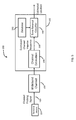
- FIG. 17 shows a view of operational principles of an exemplary time-reversal communication system.
- the transceiver B 244 first sends a probe signal 246 to the transceiver A 242 through a multi-path channel 254 . This may be referred to as the channel probing phase.
- the probe signal 246 after propagating through the channel 254 , may become a waveform 248 that is received at the transceiver A 242 .
- the transceiver A 242 time-reverses (and conjugates if the signal is complex) the received waveform 248 , and uses a time-reversed version 250 of the waveform 248 to transmit information back to the transceiver B 244 . This may be referred to as the time-reversal transmission phase.
- an emitted time-reversal signal 250 may retrace the incoming paths and form a constructive sum of signals at the intended location (i.e., the location of the transceiver B 244 ), resulting in a peak 252 in the signal-power distribution over the space, i.e., spatial focusing effect.
- time-reversal uses the multipaths as a matched filter, the transmitted signal may be focused in the time domain as well, which is referred to as the temporal focusing effect.
- the transceiver design complexity can be significantly reduced.
- a time-reversed waveform 250 can be generated by reversing the channel response waveform 248 with respect to time. If the second device 110 sends a signal having the waveform 250 , the signal will propagate in various directions, including through propagation paths 112 , 114 , and 116 (in reverse direction relative to the propagation direction of the probe pulse signal), and reach the first device 108 . In an idealized situation, the multipath signal received at the first device 108 would form a pulse signal that is similar to the pulse signal previously sent from the first device 108 to the second device 110 .
- the number of multi-path signals that can be captured at a first device 108 may be a subset of the total number of multi-paths generated by the environment.
- a first device may detect, digitize (or sample) and process a portion of a transmitted signal that travels directly along a line-of-sight between a first device and a second device.
- a first device may detect, digitize (or sample) and process one or more multi-path signals that arrive at the device within a time delay of the direct, line-of-sight signal.
- Such a time delay may be referred to as a time delay window or a channel length.
- the time delay window may be variable and may be controlled by hardware and/or software in a device.
- a first device may detect, sample and process one or more multi-path signals with certain amplitudes.
- the certain amplitude may be an amplitude above a threshold amplitude and the threshold amplitude may be fixed or may be variable and may be controlled by hardware and/or software in a device.
- different devices my collect different numbers of multipath signals and may have different settings for the time delay window or channel length, and/or amplitude threshold.
- analog-to-digital converters and digital-to-analog converters (DACs) may be used in interfaces between analog and digital circuitry.
- the ADCs and/or DACs may utilize up to two (2) bits of resolution, up to four (4) bits of resolution, up to six (6) bits of resolution, up to eight (8) bits of resolution, up to ten (10) bits of resolution, up to twelve (12) bits of resolution or more bits of resolution.
- the ADCs and/or DACs may adaptively adjust the number of bits of resolution that are being used to digitize a signal.
- an ADC or DAC in a device may utilize 4 bits of resolution under normal operating conditions but may increase the number of bits of resolution to improve the temporal and/or spatial focusing effect of the TR system.
- an ADC or DAC in a device may utilize 8 bits of resolution under normal operating conditions but may decrease the number of bits of resolution to reduce the power utilization of the device.
- the number of bits of resolution of either or both of ADCs and DACs may be an adjustable parameter in a TR transmitter and/or receiver.
- the number of bits of resolution of either or both of ADCs and DACs may be adjusted by a feedback loop and/or under software control.
- the number of bits of resolution may be a user settable parameter and may be accessed and set using a user interface and/or and application running on a device of a TR system.
- TR systems may benefit from analog-to-digital converters (ADCs) and digital-to-analog converters (DACs) with relatively high sampling rates.
- ADCs analog-to-digital converters
- DACs digital-to-analog converters
- a TR system with a 125 MHz receiver bandwidth might use ADCs and DACs with sampling rates higher than 250 MHz.
- ADCs and DACs with quoted sampling rates of 500 MHz Broader band operation of TR systems may require ADCs and DACs with GHz sampling rates.
- devices may have single input antennas or receivers and/or single output antennas or transmitters. In embodiments, devices may have multiple input antennas or receivers and/or multiple output antennas or transmitters.
- first and second devices may include single or multiple input and/or output antennas and/or single or multiple receivers and/or transmitters. Different antennas, transmitters, and/or receivers may be designed to operate at similar carrier frequencies or in similar regions of the electromagnetic spectrum or they may be designed to operate at different carrier frequencies or in different regions of the electromagnetic spectrum. Antennas, transmitters and/or receivers may have different bandwidths and may comprise different hardware components, circuits, processors, software, firmware and the like.
- the multiple antennas, transmitters and/or receivers may operate completely independently of each other or they may operate in conjunction with each other. In embodiments, a subset of antennas, transmitters and/or receivers in a device may operate independently of others or in conjunction with others. In multiple antenna, transmitter and/or receiver embodiments, the multiple antennas, transmitters and/or receivers may share certain hardware components and software code. In multiple antenna, transmitter and/or receiver embodiments, the multiple antennas, transmitters and/or receivers may operate simultaneously, independently or in a synchronized manner. For example, some or all of the antennas, transmitter and/or receivers may utilize frequency hopping techniques and the frequency hopping may be coordinated amongst the various antennas, transmitters and or receivers.
- the use of the term device and/or terminal device may mean a device with single or multiple transmitters and with single or multiple receivers and with single or multiple antennas.
- the term receiver may mean a single receiver or multiple receivers and a single antenna or multiple antennas.
- the term transmitter may mean a single transmitter or multiple transmitters and a single antenna or multiple antennas.
- a device may be any of a transmitter, a receiver and a transceiver (a combination of a transmitter and a receiver).
- wireless networks using the disclosed technology may comprise at least two devices and such networks may comprise three or more devices.
- devices may be identified as transmitters or receivers, but it should be understood that the devices could also be transceivers, radios, software radios, handsets, mobile devices, computers, routers, modems, and the like.
- Devices may be fully bi-directional or they may be configured to have more functionality as transmitters or as receivers or to support different data rates, protocols, power levels and the like in the transmit and receive modes.
- Multiple access points may communicate back and forth with each other and multiple terminal devices may communicate back and forth with each other.
- an access point may be a fixed module that allows wireless devices to be connected to a wired or another wireless network.
- Access points may support a wide variety of networking protocols and/or transmission protocols and may include or may be connected to additional computing engines and/or devices to achieve enhanced performance.
- Access points may be routers, modems, transmitters, repeaters, and the like and may be the signal source to support hot spots, local area networks, cells, microcells, nanocells, picocells, femtocells, and the like.
- Access points may support multiple wireless transmission standards, formats and protocols including, but not limited to time-reversal protocols, WiFi, 802.11xx, Bluetooth, Bluetooth LE, Zigbee, Near Field Communications (NFC), infrared communications, orthogonal frequency division multiple access (OFDMA), code division multiple access (CDMA), and the like.
- time-reversal protocols WiFi, 802.11xx, Bluetooth, Bluetooth LE, Zigbee, Near Field Communications (NFC), infrared communications, orthogonal frequency division multiple access (OFDMA), code division multiple access (CDMA), and the like.
- probe signals may be wirelessly transmitted using either omnidirectional or directional antennas, as long as the probe signal produces a multipath channel response signal at the locator.
- placing reflectors around an antenna to purposely reflect or scatter a signal in many directions may increase the number of propagation paths and may improve signal quality in a time-reversal system.
- FIG. 18 shows an exemplary multi-user time reversal positioning system 150 that includes a locator 152 and multiple terminal devices (e.g., 154 a , 154 b , 154 c , collectively 154 ). Each of the terminal devices 154 is associated with a multipath wireless channel (e.g., 156 a , 156 b , 156 c , collectively 156 ) between itself and the locator 152 .
- a multipath wireless channel e.g., 156 a , 156 b , 156 c , collectively 156
- Each multipath wireless channel 156 in the figure represents two or more multiple signal propagation paths between the corresponding terminal device and the locator.
- all the devices can operate at the same frequency band, and the system operates in multipath environments.
- the locator 152 can send multiple messages (either independent or non-independent) simultaneously to multiple selected terminals 154 .
- the base station 152 can transmit data to the terminal devices 154 a , 154 b , 154 c , and also determine the positions of the terminal devices 154 a , 154 b , and 154 c.
- the terminal device 154 can be any movable device, such as a mobile phone, a camera, a laptop computer, a tablet computer, a wearable computing device, a pair of eyeglasses, a helmet, a goggle, a car, a personal transportation device, a robot, a robotic arm, an unmanned aerial vehicle, a radio, an audio player, a health monitor, a headphone, an object tracker, a name tag, a clothing tag, a merchandise tag, a packaging box, a pen, a stylus, a watch, a bracelet, a necklace, or a cart.
- the terminal device 154 can also be a module that is attached to any of the movable devices described above.
- the terminal device 154 can be a dongle attached to a movable electronic device.
- Table 1 above includes information about a mapping between coordinates of positions and corresponding channel impulse responses.
- each set of position coordinates map to a vector of channel impulse responses representing the channel impulse responses associated with the position (e.g., 210 in FIG. 4 ) and neighboring positions (e.g., 212 ).
- the locator 182 may calculate different channel impulse responses based on the received probe waveforms. If the terminal device 154 is intended to be held at multiple orientations (e.g., users may hold mobile phones at various orientations), then during the training phase, the terminal device 154 may be held at various orientations and the locator 182 may determine the corresponding channel impulse responses. The coordinates of each position may map to a set of channel impulse responses corresponding to different orientations of the terminal device at the position.
- the positioning system 200 may be designed to support multiple types of terminal devices (e.g., several models of mobile phones and tablet computers from several manufacturers).
- various types of terminal devices may be placed at each position so that the locator 182 can determine the channel impulse response for each type of terminal device. This way, for each position in the venue, the database 192 can have information on the channel impulse responses associated with the various types of terminal devices.
- the terminal device 154 may perform a handshaking process with the locator 182 to allow the locator 182 to obtain channel information and timing information.
- the terminal device 154 may also send information about the particular type (e.g., make and model) of terminal device to the locator 182 .
- the locator 182 may compare the measured channel impulse response with pre-stored channel impulse responses associated with the particular type of terminal device to find a match.
- the channel impulse response associated with a particular position may vary over time.
- the channel impulse responses may be measured at various time periods of the day, and the channel impulse responses may be stored in the database.
- the locator 182 can be part of a mobile or stationary device.
- the locator 182 can be implemented as part of a sensor module, a controller, a mobile phone, a laptop computer, a desktop computer, a modem, a router, an access point, a base station, or an electronic appliance that communicates wirelessly with multiple other devices.
- Each of the locators 152 , 182 , and terminal devices 154 can include one or more processors and one or more computer-readable mediums (e.g., RAM, ROM, SDRAM, hard disk, optical disk, and flash memory).
- the one or more processors can perform various calculations described above. The calculations can also be implemented using application-specific integrated circuits (ASICs).
- ASICs application-specific integrated circuits
- the term “computer-readable medium” refers to a medium that participates in providing instructions to a processor for execution, including without limitation, non-volatile media (e.g., optical or magnetic disks), and volatile media (e.g., memory) and transmission media. Transmission media includes, without limitation, coaxial cables, copper wire and fiber optics.
- a computer program is a set of instructions that can be used, directly or indirectly, in a computer to perform a certain activity or bring about a certain result.
- a computer program can be written in any form of programming language (e.g., C, Java), including compiled or interpreted languages, and it can be deployed in any form, including as a stand-alone program or as a module, component, subroutine, a browser-based web application, or other unit suitable for use in a computing environment.
- Suitable processors for the execution of a program of instructions include, e.g., both general and special purpose microprocessors, digital signal processors, and the sole processor or one of multiple processors or cores, of any kind of computer.
- a processor will receive instructions and data from a read-only memory or a random access memory or both.
- the essential elements of a computer are a processor for executing instructions and one or more memories for storing instructions and data.
- a computer will also include, or be operatively coupled to communicate with, one or more mass storage devices for storing data files; such devices include magnetic disks, such as internal hard disks and removable disks; magneto-optical disks; and optical disks.
- Storage devices suitable for tangibly embodying computer program instructions and data include all forms of non-volatile memory, including by way of example semiconductor memory devices, such as EPROM, EEPROM, and flash memory devices; magnetic disks such as internal hard disks and removable disks; magneto-optical disks; and CD-ROM and DVD-ROM disks.
- semiconductor memory devices such as EPROM, EEPROM, and flash memory devices
- magnetic disks such as internal hard disks and removable disks
- magneto-optical disks and CD-ROM and DVD-ROM disks.
- the processor and the memory can be supplemented by, or incorporated in, ASICs (application-specific integrated circuits).
- ASICs application-specific integrated circuits
- the devices that communicate with the locator or base station can be different from those shown in FIG. 1A .
- the time-reversal positioning system 200 can operate at a radio frequency in a range between 0.1 GHz to 100 GHz. That is, when the terminal device 154 sends the probe signal, the carrier frequency of the probe signal can be in a range between 0.1 GHz to 100 GHz. For example, the bandwidth of the probe signal can be equal to or greater than 20 MHz.
- the time-reversal positioning system 200 can be used in combination with other positioning systems, such as those based on Wi-Fi, Bluetooth, or cellular signals.
- a mobile phone may determine a coarse position within a venue based on Wi-Fi and/or Bluetooth and/or cellular signals with an accuracy of several meters, then use the time-reversal positioning system 200 to determine a fine position with an accuracy of a few centimeters or millimeters.
- the time-reversal classifier 190 can look up the database 192 and retrieve the pre-stored information associated with the coarse position and positions in the vicinity of the coarse position, thereby significantly reducing the number of convolution operations that need to be performed.
- the terminal device 154 may be used in certain ways such that its height is more likely to be within certain ranges. By using known information about the likely position in the z-direction, it may be possible to reduce the amount of computation required at the locator 152 in order to provide a location estimate to the terminal device 154 . For example, in order to determine the position of a terminal device 154 within a room with 10 cm accuracy, one can establish a database of channel impulse responses for all possible locations where the terminal device 154 may be located using grid points spaced 10 cm apart.
- the database can have about 18 or more data points in the z-direction for each (x, y) coordinate in the room. If the terminal device 154 is typically held within a certain range of heights, the time-reversal classifier 190 can compare the received channel impulse response with pre-stored channel impulse responses that correspond to grid points in the vicinity of the likely range of heights first, potentially reducing the amount of time needed to determine the location of the terminal device 154 .
- the watch may include multi-axis accelerometers and other motion sensors that allow the operating system of the watch to determine whether the user is standing.
- the watch may be typically held within a certain range of heights. Different users may hold the watch at different heights, but for a given user the watch may be typically held within a certain range of heights in order for the user to be able to view the watch screen comfortably.
- the watch may store information about such a height range, either from past measurements performed by the indoor positioning app, or from a different app.
- the indoor positioning app may have a configuration menu that allows the user to input values representing the customary range of heights for various activities, such as standing and sitting.
- the watch can also send information regarding a likely range of heights. For example, the watch may send information to the locator 152 indicating that the watch is likely at a height within a range of, e.g., 110 cm to 130 cm.
- the locator 152 may then compare the received channel impulse response signal with pre-stored channel impulse response signals in the database that correspond to the height range of 110 cm to 130 cm. If a strong correlation is found between the received channel impulse response signal and a pre-stored channel impulse response signal associated with a height within the height range of 110 cm to 130 cm, the locator 152 may send the coordinates associated with the pre-stored channel impulse response signal to the watch as a preliminary location estimation.
- the locator 152 may continue to compare the received channel impulse response signal with pre-stored channel impulse response signals in the database that correspond to the height range outside of 110 cm to 130 cm to confirm the accuracy of the preliminary location estimation.
- the locator 152 may be able to provide preliminary location information to the watch after by searching for locations varying in height from 110 cm to 130 cm (which corresponds to 3 grid points in the z direction), potentially reducing the response time by half or more, resulting in a better user experience.
- each locator 182 can determine the coordinates of the position of the terminal device 154 .
- the multiple locators 182 can send the coordinates to the terminal device 154 , and the terminal device 154 can determine the final coordinates of the position based on the coordinates provided by the multiple locators 182 , e.g., by averaging the coordinates.
- a robot can carry the terminal device to each of the multiple positions, and the probe signal may be transmitted to the base station from each position.
- the terminal device can be part of the robot, the robot can move to each of the multiple positions, and the probe signal can be transmitted from the robot to the base station from each position.
- an unmanned aerial vehicle can carry the terminal device to each of the multiple positions, and the probe signal may be transmitted to the base station from each position.
- the terminal device can be part of the unmanned aerial vehicle, the unmanned aerial vehicle can move to each of the multiple positions, and the probe signal can be transmitted from the unmanned aerial vehicle to the base station from each position.
- a terminal device can determine its position based on pre-stored channel impulse responses downloaded from a server (e.g., access point 182 ).
- the terminal device may download the entire database D of channel impulse responses of, e.g., a shopping mall, convention center, or airport terminal from a server to facilitate navigation within the indoor venue.
- the terminal device may download a portion of the database D covering locations in the vicinity of the terminal device.
- the terminal device can determine a coarse position based on, e.g., Wi-Fi, Bluetooth, or cellular signals, and send data about the coarse position to the server.
- the terminal device may then download, from the server, information about channel responses associated with positions at or near the coarse position.
- the terminal device can receive a channel probing signal from a beacon and estimate a channel impulse response based on the received channel probing waveform.
- the terminal device can determine a time-reversed signal based on the estimated channel impulse response, and determine a fine position of the terminal device based on the time-reversed signal and the downloaded channel impulse responses.
- the locator may broadcast a combined signal that is a combination of multiple downlink signals, in which each downlink signal has coordinate data associated with a particular position, and the downlink signal has a waveform configured to focus at the particular position.
- the locator may perform a handshake process with a terminal device (e.g., 154 ) to provide timing information useful for the terminal device to determine the timing of the broadcast of the combined signal.
- the terminal device may determine its location based on the coordinate data broadcast by the locator.
- the locator may broadcast coordinate data to a subset of locations in a room at a time, and broadcast coordinate data to different subsets of locations in the room at different times, such that coordinate data are broadcast to every intended location in the room over a period of time.
- One of the advantages of this approach is that the locator does not determine the location of the terminal device, and only the terminal device knows its own precise location. This may be useful in preserving privacy of the user.
- each subset of locations may cover a small region in the room, in which different locations within the subset are close to each other.
- Each subsequent broadcast from the locator covers a different region in the room. Similar to scanning a spotlight across different regions of the floor of a room until after a period of time every portion of the floor has been illuminated for a brief period of time by the spotlight, the locator may broadcast the coordinates to various locations within a small region at a time, and scan the region across the three-dimensional room such that after a period of time, the coordinate data have been broadcast to all grid points in the room.
- each subset of locations may cover a large region in the room, in which different locations within the subset are spaced farther apart from each other (compared to the previous example).
- Each subsequent broadcast from the base station also covers a large region but shifted slightly in a certain direction (e.g., the x-, y-, or z-direction).
- the locator may broadcast the coordinates to various locations within a large region at a time, and shift the region slightly in each subsequent broadcast such that after a period of time, the coordinate data have been broadcast to all grid points in the room.
- the locator may broadcast coordinate data to another 9 m-by-9 m-by-2 m region, shifted from the previous region by 10 cm, and so forth, first shifting in the x-direction, then shifting in the y-direction, then shifting in the z-direction.
- the locator may be used in connection with motion sensors in the venue so that only when there are people moving in the room will the locator start to broadcast the coordinate data.
- the terminal device 154 does not necessarily have to be placed at grid points of an array.
- the terminal device 154 can be placed at random positions, and the database 192 can store the coordinates of those positions and their associated channel impulse responses.
- the information in the database 192 can be sorted according to the coordinates to facilitate faster retrieval.
- positioning systems based on time-reversal technology are described in the article “A Time-Reversal Paradigm for Indoor Positioning System,” which is part of U.S. patent application 62/025,795.
- the article also provides experimental results of a positioning system based on time-reversal technology.
- the positioning technology discussed in this document can be implemented in devices used in various time-reversal communication systems, such as those described in the articles “Time-Reversal Massive MIMO: Utilizing Multipaths as Virtual Antennas,” “Time-Reversal with Limited Signature Precision: Tradeoff Between Complexity and Performance,” and “Joint Waveform Design and Interference Pre-Cancellation for Time-Reversal Systems,” which are also included in U.S. patent application 62/025,795.
Landscapes
- Physics & Mathematics (AREA)
- Engineering & Computer Science (AREA)
- General Physics & Mathematics (AREA)
- Radar, Positioning & Navigation (AREA)
- Remote Sensing (AREA)
- Position Fixing By Use Of Radio Waves (AREA)
Abstract
Description
| TABLE 1 | |||
| Coordinates | |||
| (inches) | Channel responses | ||
| (0, 0, 0) | CR1 | ||
| (0.5, 0, 0) | CR2 | ||
| (1, 0, 0) | CR3 | ||
| . . . | . . . | ||
| (0, 0.5, 0) | CRn | ||
| . . . | . . . | ||
H i ={h i,1(t=t 0),h i,2(t=t 0), . . . ,h i,K(t=t 0),h i,1(t=t 1),h i,2(t=t 1), . . . ,h i,K(t=t 1), . . . ,h i,1(t=t M),h i,2(t=t M), . . . ,h i,K(t=t M)} (Equ. 1)
where hi,j(t=tl) represents the estimated channel impulse response information at neighbor j at time tl and hi,i (t=tl) represents the estimated channel impulse response information at the intended location i at time tl. The database D of channel impulse responses at various locations can be established as:
D={H i ,∀i} (Equ. 2)
H i ={h i(t=t 0),h i(t==t 1), . . . ,h i(t=t M)}, (Equ. 3)
where hi(t=tl) stands for the estimated channel impulse response information of location pi at time tl. In
where g2=[g2[0], g2[1], . . . , g2 [L−1]] is defined as the time reversed and conjugated version of h2 as follows
g 2 [k]=h 2 *[L−1−k],k=0,1, . . . ,L−1. (Equ. 5)
In an exemplary embodiment, after the locator determines the location of the device, the locator may send the location coordinates of the device, as well as other information such as the type of device, to the device and/or another locator and/or a computer and/or a server in the cloud and/or any type of computing device. In embodiments, information from the device along with its location information may be sent to other systems such as advertising systems, tracking systems, payment systems, notification systems, monitoring systems and the like. Other systems may also send information to the device. For example, the device may receive “on-sale” information for stores in its vicinity and/or for items stored on a wish-list in the phone or based on bank account information on the phone. For example, store selling expensive merchandise may send advertising information to users who have a history of purchasing higher cost items or who have considerable amounts of money in their bank accounts.
F i ={f i,1(t=t 0),f i,2(t=t 0), . . . ,f i,K(t=t 0),f i,1(t=t 1),f i,2(t=t 1), . . . ,f i,K(t=t 1), . . . ,f i,2(t=t M), . . . ,f i,K(t=t M)} (Equ. 8)
where fi,j(t=t1) is defined as follows
f i,j(t=t 1)=maxn(g*h i,j(t=t l))[n] (Equ. 9)
| TABLE 2 |
| Localization performance with 10 cm localization accuracy |
| Number of Trials | 3016 | ||
| Number of |
0 | ||
| |
0% | ||
-
- The experimental results show that, with a single locator working in the 5.4 GHz band under the non-line-of-sight condition, the time-reversal positioning system can achieve centimeter localization accuracy with a low error rate. The accuracy can be improved by, e.g., increasing the resolution of the database (i.e., reducing the distance between measurement points when establishing the channel impulse response database).
- Based on the time-reversal technique, the matching algorithm in the time-reversal positioning system is simple, which just computes the time-reversal resonating strength between the time reverse of the estimated channel impulse response and that in the database.
- A single locator can achieve a high localization accuracy even under the non-line-of-sight condition. The infrastructure cost of the time-reversal positioning system can be low. The localization performance can be further improved by using multiple access points.
Claims (20)
Priority Applications (21)
| Application Number | Priority Date | Filing Date | Title |
|---|---|---|---|
| US14/605,611 US10168414B2 (en) | 2014-07-17 | 2015-01-26 | Wireless signals and techniques for determining locations of objects in multi-path environments |
| CN201580039126.2A CN106664265B (en) | 2014-07-17 | 2015-07-17 | Wireless Location System |
| US15/326,112 US20170212210A1 (en) | 2014-07-17 | 2015-07-17 | Wireless positioning systems |
| JP2017523197A JP6688791B2 (en) | 2014-07-17 | 2015-07-17 | Wireless positioning system |
| PCT/US2015/041037 WO2016011433A2 (en) | 2014-07-17 | 2015-07-17 | Wireless positioning systems |
| EP15821676.2A EP3195541B1 (en) | 2014-07-17 | 2015-07-17 | Wireless positioning systems |
| US15/384,217 US10440705B2 (en) | 2012-12-05 | 2016-12-19 | Method, apparatus, server, and systems of time-reversal technology |
| US15/861,422 US11025475B2 (en) | 2012-12-05 | 2018-01-03 | Method, apparatus, server, and systems of time-reversal technology |
| US15/873,806 US10270642B2 (en) | 2012-12-05 | 2018-01-17 | Method, apparatus, and system for object tracking and navigation |
| US16/101,444 US10291460B2 (en) | 2012-12-05 | 2018-08-11 | Method, apparatus, and system for wireless motion monitoring |
| US16/125,748 US10833912B2 (en) | 2012-12-05 | 2018-09-09 | Methods, devices, servers, apparatus, and systems for wireless internet of things applications |
| US16/127,151 US11012285B2 (en) | 2012-12-05 | 2018-09-10 | Methods, apparatus, servers, and systems for vital signs detection and monitoring |
| US16/127,092 US10476730B2 (en) | 2008-09-23 | 2018-09-10 | Methods, apparatus, servers, and systems for human identification based on human radio biometric information |
| US16/200,616 US10495725B2 (en) | 2012-12-05 | 2018-11-26 | Method, apparatus, server and system for real-time vital sign detection and monitoring |
| US16/200,608 US10735298B2 (en) | 2012-12-05 | 2018-11-26 | Method, apparatus, server and system for vital sign detection and monitoring |
| US16/203,317 US10397039B2 (en) | 2012-12-05 | 2018-11-28 | Apparatus, systems and methods for fall-down detection based on a wireless signal |
| US16/203,299 US10374863B2 (en) | 2012-12-05 | 2018-11-28 | Apparatus, systems and methods for event recognition based on a wireless signal |
| US16/446,589 US10742475B2 (en) | 2012-12-05 | 2019-06-19 | Method, apparatus, and system for object tracking sensing using broadcasting |
| JP2020068584A JP7064679B2 (en) | 2014-07-17 | 2020-04-06 | Wireless positioning system |
| JP2022013427A JP7365587B2 (en) | 2014-07-17 | 2022-01-31 | wireless positioning system |
| US17/838,231 US20220303167A1 (en) | 2012-12-05 | 2022-06-12 | Method, apparatus, and system for identifying and qualifying devices for wireless sensing |
Applications Claiming Priority (3)
| Application Number | Priority Date | Filing Date | Title |
|---|---|---|---|
| US201462025795P | 2014-07-17 | 2014-07-17 | |
| US201462069090P | 2014-10-27 | 2014-10-27 | |
| US14/605,611 US10168414B2 (en) | 2014-07-17 | 2015-01-26 | Wireless signals and techniques for determining locations of objects in multi-path environments |
Related Parent Applications (3)
| Application Number | Title | Priority Date | Filing Date |
|---|---|---|---|
| US14/615,984 Continuation-In-Part US9686054B2 (en) | 2008-09-23 | 2015-02-06 | Joint waveform design and interference pre-cancellation for time-reversal systems |
| US15/268,477 Continuation-In-Part US9887864B1 (en) | 2008-09-23 | 2016-09-16 | Methods, devices and systems of heterogeneous time-reversal paradigm enabling direct connectivity in internet of things |
| US15/584,052 Continuation-In-Part US10447094B2 (en) | 2008-09-23 | 2017-05-02 | Method, system, and apparatus for wireless power transmission based on power waveforming |
Related Child Applications (5)
| Application Number | Title | Priority Date | Filing Date |
|---|---|---|---|
| US14/202,651 Continuation-In-Part US9226304B2 (en) | 2008-09-23 | 2014-03-10 | Time-reversal wireless paradigm for internet of things |
| PCT/US2015/041037 Continuation-In-Part WO2016011433A2 (en) | 2008-09-23 | 2015-07-17 | Wireless positioning systems |
| US15/326,112 Continuation-In-Part US20170212210A1 (en) | 2012-12-05 | 2015-07-17 | Wireless positioning systems |
| US15/061,059 Continuation-In-Part US10609711B1 (en) | 2008-09-23 | 2016-03-04 | Time-reversal scalability for high network densification |
| US15/384,217 Continuation-In-Part US10440705B2 (en) | 2008-09-23 | 2016-12-19 | Method, apparatus, server, and systems of time-reversal technology |
Publications (2)
| Publication Number | Publication Date |
|---|---|
| US20160018508A1 US20160018508A1 (en) | 2016-01-21 |
| US10168414B2 true US10168414B2 (en) | 2019-01-01 |
Family
ID=55074426
Family Applications (1)
| Application Number | Title | Priority Date | Filing Date |
|---|---|---|---|
| US14/605,611 Active US10168414B2 (en) | 2008-09-23 | 2015-01-26 | Wireless signals and techniques for determining locations of objects in multi-path environments |
Country Status (1)
| Country | Link |
|---|---|
| US (1) | US10168414B2 (en) |
Cited By (6)
| Publication number | Priority date | Publication date | Assignee | Title |
|---|---|---|---|---|
| US20180231666A1 (en) * | 2017-02-13 | 2018-08-16 | Samsung Electronics Co., Ltd. | Method and apparatus for improving gnss accuracy via path identification |
| US20190114888A1 (en) * | 2017-10-17 | 2019-04-18 | Wistron Neweb Corporation | Time-reversal indoor detection system and method |
| US20210055409A1 (en) * | 2019-08-21 | 2021-02-25 | Apical Limited | Topological model generation |
| US20210141045A1 (en) * | 2019-01-04 | 2021-05-13 | Shanghai Acoustics Laboratory, Chinese Academy Of Sciences | Fpga-based real-time processing system and method applied to underwater acoustic positioning and realizing reconfigurability and multiple output |
| US11381329B2 (en) | 2020-05-12 | 2022-07-05 | Nxp B.V. | Detecting a moving object based on a phase of channel impulse responses |
| US20230280461A1 (en) * | 2022-03-02 | 2023-09-07 | Samsung Electronics Co., Ltd. | Apparatus and method with radar |
Families Citing this family (82)
| Publication number | Priority date | Publication date | Assignee | Title |
|---|---|---|---|---|
| US11025475B2 (en) | 2012-12-05 | 2021-06-01 | Origin Wireless, Inc. | Method, apparatus, server, and systems of time-reversal technology |
| US9887864B1 (en) | 2014-03-10 | 2018-02-06 | Origin Wireless, Inc. | Methods, devices and systems of heterogeneous time-reversal paradigm enabling direct connectivity in internet of things |
| US10609711B1 (en) | 2015-03-05 | 2020-03-31 | Origin Wireless, Inc. | Time-reversal scalability for high network densification |
| US10447094B2 (en) | 2016-05-03 | 2019-10-15 | Origin Wireless, Inc. | Method, system, and apparatus for wireless power transmission based on power waveforming |
| US10129862B1 (en) | 2016-02-16 | 2018-11-13 | Origin Wireless, Inc. | Methods, devices, apparatus, and systems for medium access control in wireless communication systems utilizing spatial focusing effect |
| US10291460B2 (en) | 2012-12-05 | 2019-05-14 | Origin Wireless, Inc. | Method, apparatus, and system for wireless motion monitoring |
| US10440705B2 (en) | 2012-12-05 | 2019-10-08 | Origin Wireless, Inc. | Method, apparatus, server, and systems of time-reversal technology |
| US9407306B2 (en) | 2014-04-25 | 2016-08-02 | Origin Wireless, Inc. | Quadrature amplitude modulation for time-reversal systems |
| US10014982B1 (en) * | 2015-01-22 | 2018-07-03 | Origin Wireless, Inc. | Time-reversal technologies for hybrid wireless networks |
| US10374863B2 (en) | 2012-12-05 | 2019-08-06 | Origin Wireless, Inc. | Apparatus, systems and methods for event recognition based on a wireless signal |
| US10270642B2 (en) | 2012-12-05 | 2019-04-23 | Origin Wireless, Inc. | Method, apparatus, and system for object tracking and navigation |
| US10327213B1 (en) | 2015-10-01 | 2019-06-18 | Origin Wireless, Inc. | Time-reversal communication systems |
| US10361585B2 (en) | 2014-01-27 | 2019-07-23 | Ivani, LLC | Systems and methods to allow for a smart device |
| US9749784B1 (en) * | 2015-03-29 | 2017-08-29 | Octavio Cesar Silva | Radiofrequency identification and location system |
| IL238002B (en) * | 2015-03-29 | 2019-05-30 | Verint Systems Ltd | System and method for simultaneous location tracking of multiple wireless terminals |
| US9474042B1 (en) | 2015-09-16 | 2016-10-18 | Ivani, LLC | Detecting location within a network |
| US10321270B2 (en) | 2015-09-16 | 2019-06-11 | Ivani, LLC | Reverse-beacon indoor positioning system using existing detection fields |
| US10382893B1 (en) | 2015-09-16 | 2019-08-13 | Ivani, LLC | Building system control utilizing building occupancy |
| US10325641B2 (en) | 2017-08-10 | 2019-06-18 | Ivani, LLC | Detecting location within a network |
| US11350238B2 (en) | 2015-09-16 | 2022-05-31 | Ivani, LLC | Systems and methods for detecting the presence of a user at a computer |
| US10665284B2 (en) | 2015-09-16 | 2020-05-26 | Ivani, LLC | Detecting location within a network |
| US10455357B2 (en) | 2015-09-16 | 2019-10-22 | Ivani, LLC | Detecting location within a network |
| FR3044775B1 (en) * | 2015-12-08 | 2017-12-29 | Sigfox | METHOD FOR SELECTING, BY A TERMINAL, A COMMUNICATION MODE FOR EXCHANGING DATA WITH BASE STATIONS |
| US10380881B2 (en) | 2015-12-09 | 2019-08-13 | Origin Wireless, Inc. | Method, apparatus, and systems for wireless event detection and monitoring |
| US10129853B2 (en) | 2016-06-08 | 2018-11-13 | Cognitive Systems Corp. | Operating a motion detection channel in a wireless communication network |
| US9524628B1 (en) * | 2016-08-04 | 2016-12-20 | Cognitive Systems Corp. | Detecting signal modulation for motion detection |
| US9961662B2 (en) | 2016-09-01 | 2018-05-01 | Honeywell International Inc. | System for tracking assets |
| WO2018145044A1 (en) * | 2017-02-04 | 2018-08-09 | Federico Fraccaroli | Method and system for providing content, functionalities and services in connection with reception of an em signal |
| EP3583808B1 (en) * | 2017-02-14 | 2024-03-06 | Fraunhofer-Gesellschaft zur Förderung der angewandten Forschung e.V. | Apparatuses, systems, methods and computer program product for transmission of a positioning signal |
| US10004076B1 (en) | 2017-03-16 | 2018-06-19 | Cognitive Systems Corp. | Selecting wireless communication channels based on signal quality metrics |
| US9743294B1 (en) | 2017-03-16 | 2017-08-22 | Cognitive Systems Corp. | Storing modem parameters for motion detection |
| US9927519B1 (en) | 2017-03-16 | 2018-03-27 | Cognitive Systems Corp. | Categorizing motion detected using wireless signals |
| US9989622B1 (en) | 2017-03-16 | 2018-06-05 | Cognitive Systems Corp. | Controlling radio states for motion detection |
| US9955307B1 (en) * | 2017-08-03 | 2018-04-24 | Here Global B.V. | Distributed relative positioning |
| US10051414B1 (en) | 2017-08-30 | 2018-08-14 | Cognitive Systems Corp. | Detecting motion based on decompositions of channel response variations |
| US10109167B1 (en) | 2017-10-20 | 2018-10-23 | Cognitive Systems Corp. | Motion localization in a wireless mesh network based on motion indicator values |
| US10228439B1 (en) | 2017-10-31 | 2019-03-12 | Cognitive Systems Corp. | Motion detection based on filtered statistical parameters of wireless signals |
| US10048350B1 (en) | 2017-10-31 | 2018-08-14 | Cognitive Systems Corp. | Motion detection based on groupings of statistical parameters of wireless signals |
| US9933517B1 (en) | 2017-11-03 | 2018-04-03 | Cognitive Systems Corp. | Time-alignment of motion detection signals using buffers |
| US10605908B2 (en) * | 2017-11-15 | 2020-03-31 | Cognitive Systems Corp. | Motion detection based on beamforming dynamic information from wireless standard client devices |
| US10109168B1 (en) * | 2017-11-16 | 2018-10-23 | Cognitive Systems Corp. | Motion localization based on channel response characteristics |
| US10264405B1 (en) | 2017-12-06 | 2019-04-16 | Cognitive Systems Corp. | Motion detection in mesh networks |
| US10852411B2 (en) * | 2017-12-06 | 2020-12-01 | Cognitive Systems Corp. | Motion detection and localization based on bi-directional channel sounding |
| US10108903B1 (en) | 2017-12-08 | 2018-10-23 | Cognitive Systems Corp. | Motion detection based on machine learning of wireless signal properties |
| US11687753B2 (en) * | 2018-03-13 | 2023-06-27 | University Of Louisville | Frequency selective surfaces for tracking, labeling and identification |
| US10393866B1 (en) | 2018-03-26 | 2019-08-27 | Cognitive Systems Corp. | Detecting presence based on wireless signal analysis |
| US10733859B2 (en) * | 2018-05-01 | 2020-08-04 | Satellite Tracking Of People Llc | System and method of alternative tracking upon disabling of monitoring device |
| US10318890B1 (en) | 2018-05-23 | 2019-06-11 | Cognitive Systems Corp. | Training data for a motion detection system using data from a sensor device |
| US11579703B2 (en) | 2018-06-18 | 2023-02-14 | Cognitive Systems Corp. | Recognizing gestures based on wireless signals |
| CN112823289B (en) * | 2018-10-12 | 2024-07-05 | 因温特奥股份公司 | System and method for position determination in a building |
| US11610446B2 (en) | 2018-10-12 | 2023-03-21 | Inventio Ag | Access control system and method for operating an access control system |
| US10506384B1 (en) | 2018-12-03 | 2019-12-10 | Cognitive Systems Corp. | Determining a location of motion detected from wireless signals based on prior probability |
| US11403543B2 (en) | 2018-12-03 | 2022-08-02 | Cognitive Systems Corp. | Determining a location of motion detected from wireless signals |
| CN109464075A (en) * | 2018-12-07 | 2019-03-15 | 江苏美的清洁电器股份有限公司 | Cleaning control method and device for sweeping robot and sweeping robot |
| US10499364B1 (en) | 2019-01-24 | 2019-12-03 | Cognitive Systems Corp. | Identifying static leaf nodes in a motion detection system |
| US10498467B1 (en) | 2019-01-24 | 2019-12-03 | Cognitive Systems Corp. | Classifying static leaf nodes in a motion detection system |
| US10565860B1 (en) * | 2019-03-21 | 2020-02-18 | Cognitive Systems Corp. | Offline tuning system for detecting new motion zones in a motion detection system |
| US10798529B1 (en) | 2019-04-30 | 2020-10-06 | Cognitive Systems Corp. | Controlling wireless connections in wireless sensing systems |
| US10459074B1 (en) | 2019-04-30 | 2019-10-29 | Cognitive Systems Corp. | Determining a location of motion detected from wireless signals based on wireless link counting |
| US10567914B1 (en) | 2019-04-30 | 2020-02-18 | Cognitive Systems Corp. | Initializing probability vectors for determining a location of motion detected from wireless signals |
| US10600314B1 (en) | 2019-04-30 | 2020-03-24 | Cognitive Systems Corp. | Modifying sensitivity settings in a motion detection system |
| US10404387B1 (en) | 2019-05-15 | 2019-09-03 | Cognitive Systems Corp. | Determining motion zones in a space traversed by wireless signals |
| US10460581B1 (en) | 2019-05-15 | 2019-10-29 | Cognitive Systems Corp. | Determining a confidence for a motion zone identified as a location of motion for motion detected by wireless signals |
| US10743143B1 (en) | 2019-05-15 | 2020-08-11 | Cognitive Systems Corp. | Determining a motion zone for a location of motion detected by wireless signals |
| JP2021001833A (en) * | 2019-06-24 | 2021-01-07 | アライドテレシスホールディングス株式会社 | Position estimating device and method |
| EP3819657A1 (en) * | 2019-11-07 | 2021-05-12 | Fraunhofer Gesellschaft zur Förderung der angewandten Forschung e.V. | Methods and apparatuses for positioning in a wireless communications network |
| US10952181B1 (en) | 2019-09-30 | 2021-03-16 | Cognitive Systems Corp. | Detecting a location of motion using wireless signals in a wireless mesh network that includes leaf nodes |
| US11570712B2 (en) | 2019-10-31 | 2023-01-31 | Cognitive Systems Corp. | Varying a rate of eliciting MIMO transmissions from wireless communication devices |
| CN114599991B (en) | 2019-10-31 | 2025-02-28 | 认知系统公司 | Inducing MIMO transmission from a wireless communication device |
| CA3152905A1 (en) | 2019-10-31 | 2021-05-06 | Christopher Beg | Using mimo training fields for motion detection |
| US10928503B1 (en) | 2020-03-03 | 2021-02-23 | Cognitive Systems Corp. | Using over-the-air signals for passive motion detection |
| US12019143B2 (en) | 2020-03-03 | 2024-06-25 | Cognitive Systems Corp. | Using high-efficiency PHY frames for motion detection |
| US11495243B2 (en) | 2020-07-30 | 2022-11-08 | Lawrence Livermore National Security, Llc | Localization based on time-reversed event sounds |
| WO2022040817A1 (en) | 2020-08-31 | 2022-03-03 | Cognitive Systems Corp. | Controlling motion topology in a standardized wireless communication network |
| CN112422894B (en) * | 2020-10-14 | 2022-10-14 | 重庆恢恢信息技术有限公司 | Method for processing construction site video image through cloud platform mass data |
| US11070399B1 (en) | 2020-11-30 | 2021-07-20 | Cognitive Systems Corp. | Filtering channel responses for motion detection |
| CN112584491B (en) * | 2020-12-30 | 2022-06-28 | 重庆赤木科技有限公司 | Target positioning system based on WiFi probe |
| CN114339598A (en) * | 2021-12-31 | 2022-04-12 | 天翼物联科技有限公司 | UWB imaging positioning method and system based on time reversal |
| CN114844776B (en) * | 2022-04-22 | 2023-04-18 | 电子科技大学 | Electromagnetic imaging positioning method and device based on time reversal time domain characteristics |
| CN117835143A (en) * | 2022-09-27 | 2024-04-05 | 中兴通讯股份有限公司 | Wireless sensing method and device, communication equipment and computer storage medium |
| CN115932926A (en) * | 2022-11-16 | 2023-04-07 | 浙江飞碟汽车制造有限公司 | A Method to Shorten the Initialization Time of Multi-sensor Fusion Positioning |
| CN116256739B (en) * | 2023-03-27 | 2023-11-14 | 烟台欣飞智能系统有限公司 | Moving target coordinate positioning system based on radio multipoint detection |
Citations (47)
| Publication number | Priority date | Publication date | Assignee | Title |
|---|---|---|---|---|
| US2933702A (en) | 1956-11-29 | 1960-04-19 | Bell Telephone Labor Inc | Time reversal delay distortion corrector |
| US3767855A (en) | 1971-02-25 | 1973-10-23 | Nippon Electric Co | Pulse position modulation communication system |
| US5092336A (en) | 1989-02-08 | 1992-03-03 | Universite Paris Vii-Bureau De La Valorisation Et De Relations Industrielle | Method and device for localization and focusing of acoustic waves in tissues |
| US5155742A (en) | 1991-05-03 | 1992-10-13 | Bell Communications Research, Inc. | Time dispersion equalizer receiver with a time-reversal structure for TDMA portable radio systems |
| US5428999A (en) | 1992-10-02 | 1995-07-04 | Universite Paris Vii | Method and apparatus for acoustic examination using time reversal |
| US5926768A (en) | 1996-04-24 | 1999-07-20 | Lewiner; Jacques | Method of optimizing radio communication between a base and a mobile |
| US6301291B1 (en) | 2000-02-03 | 2001-10-09 | Tantivy Communications, Inc. | Pilot symbol assisted modulation and demodulation in wireless communication systems |
| US6490469B2 (en) | 2000-03-15 | 2002-12-03 | The Regents Of The University Of California | Method and apparatus for dynamic focusing of ultrasound energy |
| US20030138053A1 (en) | 2001-11-15 | 2003-07-24 | The Regents Of The University Of California | Time reversal communication system |
| US20040156443A1 (en) | 2003-02-10 | 2004-08-12 | Dent Paul W. | Using antenna arrays in multipath environment |
| US6862326B1 (en) | 2001-02-20 | 2005-03-01 | Comsys Communication & Signal Processing Ltd. | Whitening matched filter for use in a communications receiver |
| US20050046584A1 (en) * | 1992-05-05 | 2005-03-03 | Breed David S. | Asset system control arrangement and method |
| US20060098746A1 (en) | 2002-11-06 | 2006-05-11 | The Regents Of The University Of California | Multi-channel time-reversal receivers for multi and 1-bit implementations |
| US20060115031A1 (en) | 2000-04-14 | 2006-06-01 | Lindskog Erik D | Time-reversal block transmit diversity system for channels with intersymbol interference and method |
| US20070010956A1 (en) | 2003-09-26 | 2007-01-11 | Chahe Nerguizian | Method and system for indoor geolocation using an impulse response fingerprinting technique |
| WO2007031088A1 (en) | 2005-09-15 | 2007-03-22 | Aalborg Universited | A method for sending secure information or increasing communication capacity via coding of wavefronts and a system using said method |
| US20080039114A1 (en) | 2006-08-11 | 2008-02-14 | Sirf Technology, Inc. | Cell id based positioning from cell intersections |
| US7440766B1 (en) | 2004-06-07 | 2008-10-21 | University Of Hawaii | Method for employing multipath propagation in wireless radio communications |
| US7587291B1 (en) | 2008-05-05 | 2009-09-08 | Artann Laboratories | Focusing of broadband acoustic signals using time-reversed acoustics |
| US7768876B2 (en) | 2004-12-21 | 2010-08-03 | Elliptic Laboratories As | Channel impulse response estimation |
| US20100302977A1 (en) | 2007-12-21 | 2010-12-02 | France Telecom | Time-reversal method of pre-equalizing a data signal |
| US20100309829A1 (en) | 2007-12-21 | 2010-12-09 | France Telecom | Time-reversal pre-equalization method |
| WO2011029072A2 (en) | 2009-09-03 | 2011-03-10 | Ziva Corporation | Techniques and systems for providing data over power in communications based on time reversal |
| US20110164708A1 (en) * | 2010-01-04 | 2011-07-07 | Industrial Technology Research Institute | Symbol timing methods and apparatuses using the same in multi-carrier receiving systems |
| US20120056777A1 (en) * | 2010-09-06 | 2012-03-08 | Hisashi Shiba | Target detection system, detection method, and detection information processing program |
| US8195112B1 (en) | 2008-06-18 | 2012-06-05 | Marvell International Ltd. | Time-reversal-based communication |
| US20120183037A1 (en) | 2011-01-14 | 2012-07-19 | Stephen Allpress | Equalisation of a signal received over a wireless channel |
| US20120207234A1 (en) | 2009-11-09 | 2012-08-16 | Centre National De La Recherche Scientifique-Cnrs- | Method for Transmitting Digital Data, and Transmitter Base Implementing Such a Method |
| US20120257660A1 (en) | 2008-10-10 | 2012-10-11 | Smith David F | Techniques and systems for wireless communications |
| US20120263056A1 (en) | 2011-04-15 | 2012-10-18 | David Smith | Apparatus, methods, and articles of manufacture for wireless communications |
| WO2012151316A1 (en) | 2011-05-02 | 2012-11-08 | Ziva Corporation | Distributed co-operating nodes using time reversal |
| US20120328037A1 (en) * | 2011-04-15 | 2012-12-27 | Mark Hsu | Anti-geolocation |
| US8346197B2 (en) | 2008-04-11 | 2013-01-01 | France Telecom | Method of dynamically compensating a relative movement of a communicating entity |
| EP2571214A2 (en) | 2011-09-15 | 2013-03-20 | Exelis, Inc. | Method and apparatus for cooperative communications between groups of communication units using a time reversed channel response |
| US8451181B2 (en) | 2008-06-27 | 2013-05-28 | France Telecom | Method of estimating the focusing quality of a signal pre-equalized by time reversal |
| US8457217B2 (en) | 2008-06-27 | 2013-06-04 | France Telecom | Method of dynamic control of the focusing of a signal pre-equalized by time reversal |
| US20130201958A1 (en) | 2010-10-22 | 2013-08-08 | France Telecom | Radio communication method and device for multiple user antennas |
| WO2013126054A1 (en) | 2012-02-22 | 2013-08-29 | Halliburton Energy Services, Inc. | Downhole telemetry systems and methods with time-reversal pre-equalization |
| US8593998B2 (en) | 2007-03-05 | 2013-11-26 | France Telecom | Time reversal method of processing symbols in bidirectional communication |
| US20140022128A1 (en) * | 2012-01-13 | 2014-01-23 | Ziva Corporation | Geolocation |
| US20140105054A1 (en) * | 2011-05-16 | 2014-04-17 | Radionor Communication As | Method and System for Long-Range Adaptive Mobile Beam-Forming Ad-Hoc Communication System with Integrated Positioning |
| US20140185596A1 (en) | 2012-12-03 | 2014-07-03 | University Of Maryland At College Park | Systems and methods for time-reversal division multiple access wireless broadband communications |
| US8792396B2 (en) | 2009-05-07 | 2014-07-29 | France Telecom | Method of pre-equalizing a data signal by time reversal in FDD |
| US20150049745A1 (en) | 2013-08-16 | 2015-02-19 | Origin Wireless Communications, Inc. | Time-reversal wireless systems having asymmetric architecture |
| US20150049792A1 (en) | 2013-08-16 | 2015-02-19 | Origin Wireless Communications, Inc. | Multiuser time-reversal division multiple access uplink system with parallel interference cancellation |
| US20150247915A1 (en) * | 2014-02-28 | 2015-09-03 | Alcatel-Lucent Usa Inc. | Method And Apparatus For Determining Tag Location |
| US20150257167A1 (en) * | 2014-03-10 | 2015-09-10 | Origin Wireless Communications, Inc. | Time-reversal wireless paradigm for internet of things |
-
2015
- 2015-01-26 US US14/605,611 patent/US10168414B2/en active Active
Patent Citations (58)
| Publication number | Priority date | Publication date | Assignee | Title |
|---|---|---|---|---|
| US2933702A (en) | 1956-11-29 | 1960-04-19 | Bell Telephone Labor Inc | Time reversal delay distortion corrector |
| US3767855A (en) | 1971-02-25 | 1973-10-23 | Nippon Electric Co | Pulse position modulation communication system |
| US5092336A (en) | 1989-02-08 | 1992-03-03 | Universite Paris Vii-Bureau De La Valorisation Et De Relations Industrielle | Method and device for localization and focusing of acoustic waves in tissues |
| US5155742A (en) | 1991-05-03 | 1992-10-13 | Bell Communications Research, Inc. | Time dispersion equalizer receiver with a time-reversal structure for TDMA portable radio systems |
| US20050046584A1 (en) * | 1992-05-05 | 2005-03-03 | Breed David S. | Asset system control arrangement and method |
| US5428999A (en) | 1992-10-02 | 1995-07-04 | Universite Paris Vii | Method and apparatus for acoustic examination using time reversal |
| US5926768A (en) | 1996-04-24 | 1999-07-20 | Lewiner; Jacques | Method of optimizing radio communication between a base and a mobile |
| US6301291B1 (en) | 2000-02-03 | 2001-10-09 | Tantivy Communications, Inc. | Pilot symbol assisted modulation and demodulation in wireless communication systems |
| US6490469B2 (en) | 2000-03-15 | 2002-12-03 | The Regents Of The University Of California | Method and apparatus for dynamic focusing of ultrasound energy |
| US7362815B2 (en) | 2000-04-14 | 2008-04-22 | Board Of Trustees Of The Leland Stanford Junior University | Time-reversal block transmit diversity system for channels with intersymbol interference and method |
| US20060115031A1 (en) | 2000-04-14 | 2006-06-01 | Lindskog Erik D | Time-reversal block transmit diversity system for channels with intersymbol interference and method |
| US6862326B1 (en) | 2001-02-20 | 2005-03-01 | Comsys Communication & Signal Processing Ltd. | Whitening matched filter for use in a communications receiver |
| US20030138053A1 (en) | 2001-11-15 | 2003-07-24 | The Regents Of The University Of California | Time reversal communication system |
| US7460605B2 (en) | 2001-11-15 | 2008-12-02 | Lawrence Livermore National Security, Llc | Time reversal communication system |
| US20060098746A1 (en) | 2002-11-06 | 2006-05-11 | The Regents Of The University Of California | Multi-channel time-reversal receivers for multi and 1-bit implementations |
| US7463690B2 (en) | 2002-11-06 | 2008-12-09 | Lawrence Livermore National Security, Llc | Multi-channel time-reversal receivers for multi and 1-bit implementations |
| US20040156443A1 (en) | 2003-02-10 | 2004-08-12 | Dent Paul W. | Using antenna arrays in multipath environment |
| US20070010956A1 (en) | 2003-09-26 | 2007-01-11 | Chahe Nerguizian | Method and system for indoor geolocation using an impulse response fingerprinting technique |
| US7440766B1 (en) | 2004-06-07 | 2008-10-21 | University Of Hawaii | Method for employing multipath propagation in wireless radio communications |
| US7768876B2 (en) | 2004-12-21 | 2010-08-03 | Elliptic Laboratories As | Channel impulse response estimation |
| WO2007031088A1 (en) | 2005-09-15 | 2007-03-22 | Aalborg Universited | A method for sending secure information or increasing communication capacity via coding of wavefronts and a system using said method |
| US20080039114A1 (en) | 2006-08-11 | 2008-02-14 | Sirf Technology, Inc. | Cell id based positioning from cell intersections |
| US8593998B2 (en) | 2007-03-05 | 2013-11-26 | France Telecom | Time reversal method of processing symbols in bidirectional communication |
| US20100302977A1 (en) | 2007-12-21 | 2010-12-02 | France Telecom | Time-reversal method of pre-equalizing a data signal |
| US20100309829A1 (en) | 2007-12-21 | 2010-12-09 | France Telecom | Time-reversal pre-equalization method |
| US8346197B2 (en) | 2008-04-11 | 2013-01-01 | France Telecom | Method of dynamically compensating a relative movement of a communicating entity |
| US7587291B1 (en) | 2008-05-05 | 2009-09-08 | Artann Laboratories | Focusing of broadband acoustic signals using time-reversed acoustics |
| US8195112B1 (en) | 2008-06-18 | 2012-06-05 | Marvell International Ltd. | Time-reversal-based communication |
| US8457217B2 (en) | 2008-06-27 | 2013-06-04 | France Telecom | Method of dynamic control of the focusing of a signal pre-equalized by time reversal |
| US8451181B2 (en) | 2008-06-27 | 2013-05-28 | France Telecom | Method of estimating the focusing quality of a signal pre-equalized by time reversal |
| US20130223503A1 (en) * | 2008-10-10 | 2013-08-29 | Ziva Corporation | Reducing signal degradation in wireless communications based on time reversal |
| US8411765B2 (en) | 2008-10-10 | 2013-04-02 | Ziva Corporation | Techniques and systems for wireless communications |
| US20120257660A1 (en) | 2008-10-10 | 2012-10-11 | Smith David F | Techniques and systems for wireless communications |
| US8792396B2 (en) | 2009-05-07 | 2014-07-29 | France Telecom | Method of pre-equalizing a data signal by time reversal in FDD |
| US8498658B2 (en) | 2009-09-03 | 2013-07-30 | Ziva Corporation | Techniques and systems for providing data over power in communications based on time reversal |
| WO2011029072A2 (en) | 2009-09-03 | 2011-03-10 | Ziva Corporation | Techniques and systems for providing data over power in communications based on time reversal |
| US8743976B2 (en) | 2009-09-03 | 2014-06-03 | Ziva Corporation | Techniques and systems for communications based on time reversal pre-coding |
| WO2011029075A2 (en) | 2009-09-03 | 2011-03-10 | Ziva Corporation | Techniques and systems for communications based on time reversal pre-coding |
| US20120155515A1 (en) | 2009-09-03 | 2012-06-21 | Ziva Corporation | Techniques and systems for providing data over power in communications based on time reversal |
| US20120207234A1 (en) | 2009-11-09 | 2012-08-16 | Centre National De La Recherche Scientifique-Cnrs- | Method for Transmitting Digital Data, and Transmitter Base Implementing Such a Method |
| US20110164708A1 (en) * | 2010-01-04 | 2011-07-07 | Industrial Technology Research Institute | Symbol timing methods and apparatuses using the same in multi-carrier receiving systems |
| US20120056777A1 (en) * | 2010-09-06 | 2012-03-08 | Hisashi Shiba | Target detection system, detection method, and detection information processing program |
| US20130201958A1 (en) | 2010-10-22 | 2013-08-08 | France Telecom | Radio communication method and device for multiple user antennas |
| US20120183037A1 (en) | 2011-01-14 | 2012-07-19 | Stephen Allpress | Equalisation of a signal received over a wireless channel |
| US20120328037A1 (en) * | 2011-04-15 | 2012-12-27 | Mark Hsu | Anti-geolocation |
| US20120263056A1 (en) | 2011-04-15 | 2012-10-18 | David Smith | Apparatus, methods, and articles of manufacture for wireless communications |
| US20140126567A1 (en) | 2011-05-02 | 2014-05-08 | Anis Husain | Distributed co-operating nodes using time reversal |
| WO2012151316A1 (en) | 2011-05-02 | 2012-11-08 | Ziva Corporation | Distributed co-operating nodes using time reversal |
| US20140105054A1 (en) * | 2011-05-16 | 2014-04-17 | Radionor Communication As | Method and System for Long-Range Adaptive Mobile Beam-Forming Ad-Hoc Communication System with Integrated Positioning |
| US8831164B2 (en) | 2011-09-15 | 2014-09-09 | Exelis Inc | Method and apparatus for cooperative communications between groups of communication units using a time reversed channel response |
| EP2571214A2 (en) | 2011-09-15 | 2013-03-20 | Exelis, Inc. | Method and apparatus for cooperative communications between groups of communication units using a time reversed channel response |
| US20140022128A1 (en) * | 2012-01-13 | 2014-01-23 | Ziva Corporation | Geolocation |
| WO2013126054A1 (en) | 2012-02-22 | 2013-08-29 | Halliburton Energy Services, Inc. | Downhole telemetry systems and methods with time-reversal pre-equalization |
| US20140185596A1 (en) | 2012-12-03 | 2014-07-03 | University Of Maryland At College Park | Systems and methods for time-reversal division multiple access wireless broadband communications |
| US20150049745A1 (en) | 2013-08-16 | 2015-02-19 | Origin Wireless Communications, Inc. | Time-reversal wireless systems having asymmetric architecture |
| US20150049792A1 (en) | 2013-08-16 | 2015-02-19 | Origin Wireless Communications, Inc. | Multiuser time-reversal division multiple access uplink system with parallel interference cancellation |
| US20150247915A1 (en) * | 2014-02-28 | 2015-09-03 | Alcatel-Lucent Usa Inc. | Method And Apparatus For Determining Tag Location |
| US20150257167A1 (en) * | 2014-03-10 | 2015-09-10 | Origin Wireless Communications, Inc. | Time-reversal wireless paradigm for internet of things |
Non-Patent Citations (99)
| Title |
|---|
| Abbasi-Moghadam, D. and V.T. Vakili, "A SIMO one-bit time reversal for UWB communication systems", EURASIP J. Wireless Comm. and Networking, 2012:113, 2012. |
| Albert, D., L. Liu, M. L. Moran, "Time Reversal processing for source location in an urban environment (L)", J. Acoust. Soc. Am., vol. 118, No. 2, pp. 616-619, Aug. 2005. |
| Bahl, P. and Padmanabhan, V., "Radar: An In-Building RF-based User Location and Tracking System", IEEE INFOCOM, pp. 775-784 (2000). |
| Brysev, A.P., L.M. Krutyanskii, V'L. Preobrazhenskii, "Wave Phase Conjugation in ultrasonic beams", Physics-Uspekhi, vol. 41, No. 8, pp. 793-805, 1998. |
| Chang, Y.H., S.H. Tsai, X. Yu, C.C. J. Kuo, "Ultrawideband Transceiver Design Using Channel Phase Precoding", IEEE Trans. Sig. Proc., vol. 55, No. 7, pp. 3807-3822, Jul. 2007. |
| Chen, Y. et al., "Time-reversal wideband communications," IEEE Signal Processing Letters, vol. 20(12):1219-1222 (Dec. 2013). |
| Chen, Y., F. Han, Y.H. Yang, H. Ma, Y. Han, C. Jiang, H.Q. Lai, D. Claffey, Z. Safar, K.J.R. Liu, "Time-Reversal Wireless Paradigm for Green Internet of Things: An Overview", IEEE Internet of Things Journal, vol. 1, No. 1, Feb. 2014. |
| Daniels, R.C. and R. W. Heath, "Improving on time-reversal with MISO precoding," in the Proceedings IWC/WPMC, Aalborg, Denmark, Sep. 2005. |
| Daniels, R.C. and R. W. Heath, "MISO precoding for temporal and spatial focusing" in the Proceedings of the Eighth International Symposium on Wireless Personal Communications Conference, Aalborg, Denmark, 2005. |
| De Rosny, J., G. Lerosey and M. Fink, "Theory of Electromagnetic Time-Reversal Mirrors", IEEE Trans. Antennas Propag., vol. 58, No. 10, pp. 3139-3149, Oct. 2010. |
| Derode, A., A. Tourin, and M. Fink, "Ultrasonic pulse compression with one-bit time reversal through multiple scattering", J. Appl. Phys., vol. 85, No. 9, pp. 6343-6352, May 1999. |
| Derode, A., A. Tourin, J. de Rosny, M. Tanter, S. Yon, and M. Fink, "Taking Advantage of Multiple Scattering to Communicate with Time-Reversal Antennas", Phys. Rev. Lett., vol. 90, No. 1, 014301, Jan. 2003. |
| Derode, A., P. Roux, and M. Fink, "Robust Acoustic Time Reversal and High-Order Multiple Scattering", Phys. Rev. Lett., vol. 75, No. 23, pp. 4206-4210, Dec. 1995. |
| Dorme, C. and M. Fink, "Focusing in transmit-receive mode through inhomogeneous media: The time reversal matched filter approach", J. Acoust. Soc. Am., vol. 98, Pt. 1, pp. 1155-1162, Aug. 1995. |
| Edelmann, G.F., T. Akal, W.S. Hodgkiss, S. Kim, W.A. Kuperman and H.C. Song, "An Initial Demonstration of Underwater Acoustic Communication Using Time Reversal", IEEE J. Ocean Eng., vol. 27, No. 3, Jul. 2002. |
| Emami et al., "Matched Filtering with Rate Back-off for Low Complexity Communications in Very Large Delay Spread Channels," 38th Asilomar Conference on Signals, Systems and Computers, pp. 218-222, 2004. |
| Emami, S.M., J. Hansen, A.D. Kim, G. Papanicolaou, A.J. Paulraj, D. Cheung, C. Prettie, "Predicted Time Reversal Performance in Wireless Communications using Channel Measurements", publication details unknown. |
| Fink, M. and C. Prada, "Acoustic Time-Reversal Mirrors", Inverse Problems, vol. 17, pp. R1-R38, 2001. |
| Fink, M., "Time Reversal of Ultrasonic Fields-Part I: Basic Principals", IEEE Trans. Ultrasonics, Ferroelectrics and Freq. Contr., vol. 39, No. 5, pp. 555-566, Sep. 1992. |
| Fink, M., "Time-Reversal Mirrors", J. Phys. D: Appl. Phys., vol. 26, pp. 1333-1350, 1993. |
| Fink, M., "Time-Reversed Acoustics", Scientific American, pp. 91-97, Nov. 1999. |
| Fink, M., "Time Reversal of Ultrasonic Fields—Part I: Basic Principals", IEEE Trans. Ultrasonics, Ferroelectrics and Freq. Contr., vol. 39, No. 5, pp. 555-566, Sep. 1992. |
| Fink, M., C. Prada, F. Wu, and D. Cassereau, "Self focusing in inhomogeneous media with time reversal acoustic mirrors," IEEE Ultrasonics Symposium, vol. 1, pp. 681-686, 1989. |
| Fontana, R.J., S.J. Gunderson, "Ultra-Wideband Precision Asset Location System", Proc. of the IEEE Conf. on UWB Sys. and Tech., pp. 147-150, 2002. |
| Guo, N., B.M. Sadler and R.C. Qiu, "Reduced-Complexity UWB Time-Reversal Techniques and Experimental Results", IEEE Trans. on Wireless Comm., vol. 6, No. 12, Dec. 2007. |
| Gwon, Youngjune and Jain, Ravi, "Error Characteristics and Calibration-free Techniques for Wireless LAN-based Location Estimation", MobiWac '04, 8 pages (2004). |
| Han, F. and K.J.R. Liu, "A multiuser TRDMA uplink system with 2D parallel interference cancellation," IEEE Transactions on Communications, vol. 62(3):1011-1022 (Mar. 2014). |
| Han, F. and K.J.R. Liu, "An Interference Cancellation Scheme for the Multiuser TRDMA Uplink System," Global Telecommunications Conference, pp. 3583-3588 (2013). |
| Han, F., "Energy Efficient Optimization in Green Wireless Networks", University of Maryland Ph. D. Dissertation, 2013. |
| Han, F., Y.H. Yang, B. Wang, Y. Wu, K.J.R. Liu, "Time-reversal division multiple access in multi-path channels," Global Telecommunications Conference, pp. 1-5 (2011). |
| Han, F., Y.H. Yang, B. Wang, Y. Wu, K.J.R. Liu, "Time-reversal division multiple access over multi-path channels," IEEE Transactions on Communications, vol. 60(7):1953-1965 (Jul. 2012). |
| Han, F., Yang, Y.-H., Wang, B., Wu, Y., Liu, K.J.R., "Time-reversal division multiple access in multi-path channels", IEEE Globecom, Houston, Dec. 2011. |
| Han, F., Yang, Y-H., Wang, B., Y. Wu, K.J.R. Liu, "Time-reversal division multiple access over multi-path channels", IEEE Trans. on Communications, vol. 60:1953-1965, Jul. 2012. |
| Han, Y., Chen, Y., and Liu, K.J.R, ‘Time-Reversal with Limited Signature Precision: Tradeoff Between Complexity and Performance’, Proc. IEEE Global Conference on Signal and Information Processing (GlobalSIP), Atlanta, Dec. 2014. |
| Han, Y., Chen, Y., and Liu, K.J.R, 'Time-Reversal with Limited Signature Precision: Tradeoff Between Complexity and Performance', Proc. IEEE Global Conference on Signal and Information Processing (GlobalSIP), Atlanta, Dec. 2014. |
| Henty, B.E. and D.D. Stancil, "Multipath-Enabled Super-Resolution for rf and Microwave Communication using Phase-Conjugate Arrays", Phys. Rev. Lett., vol. 93, 243904, Dec. 2004. |
| International Search Report and Written Opinion issued in International Application No. PCT/US2015/041037 dated Jan. 11, 2016, 14 pages. |
| Jin, Jy. and .M.F. Moura, "Time Reversal Detection Using Antenna Arrays", IEEE Trans. on Signal Process., vol. 57, No. 4, Apr. 2009. |
| Khalegi, A., G. El Zein and I. Navqi, "Demonstration of Time-Reversal in Indoor Ultra-Wideband Communication: Time Domain Measurement", IEEE Proc. of ISWCS, pp. 465-468, 2007. |
| Kuperman, W.A., W.S. Hodgkiss, H.C. Song, T. Akal, C. Ferla, D.R. Jackson, "Phase conjugation in the ocean: Experimental demonstration pf an acoustic time-reversal mirror", J. Acoust. Soc. Am., vol. 103, No. 1, pp. 25-40, Jan. 1998. |
| Kyritsi, P. and G. Papanicolau, "One-bit Time Reversal for WLAN Applications", IEEE 16th Intern. Symp. on Personal, Indoor and Mobile Radio Comm., pp. 532-536, 2005. |
| Kyritsi, P. et al., "Time reversal and zero-forcing equalization for fixed wireless access channels," 39th Asilomar Conference on Signals, Systems and Computers, pp. 1297-1301 (2005). |
| Kyritsi, P. et al., "Time reversal techniques for wireless communications," IEEE Vehicular Technology Conference, vol. 1:47-51 (2004). |
| Lemoult, F., G. Lerosey, J. de Rosny, and M. Fink, "Manipulating Spatiotemporal Degrees of Freedom in Waves of Random Media", Phys. Rev. Lett., vol. 103, 173902, Oct. 2009. |
| Lemoult, F., G. Lerosey, J. de Rosny, and M. Fink, "Resonant Metalenses for Breaking the Diffraction Barrier", Phys. Rev. Lett., vol. 104, 203901, May 2010. |
| Lerosey, G. et al., "Focusing Beyond the Deffraction Limit with Far-Field Time Reversal", Science, vol. 315:1120-1122 (Feb. 2007). |
| Lerosey, G., J. de Rosny, A. Tourin, A. Derode, G. Montaldo and M. Fink, "Time Reversal of Electromagnetic Waves and Telecommunication", Radio Science, vol. 40, RS6S12, 2005. |
| Lerosey, G., J. de Rosny, A. Tourin, A. Derode, G. Montaldo and M. Fink, "Time Reversal of Electromagnetic Waves", Phys. Rev. Lett., vol. 92, No. 19, 193904, May 2004. |
| Lerosey, G., J. de Rosny, A. Tourin, A. Derode, M. Fink, "Time Reversal of Wideband Microwaves", Appl. Phys. Lett., vol. 88, 154101, Apr. 2006. |
| Lerosey, G., J. de Rosny, A. Tourin, and M. Fink, "Focusing beyond the diffraction limit with far-field time reversal", Science, vol. 315, pp. 1120-1122, Feb. 2007. |
| Lienard, M. et al., "Focusing gain model of time-reversed signals in dense multipath channels," IEEE Antennas and Wireless Propagation Letters, vol. 11:1064-1067 ( 2012). |
| Lim, Hyuk et al., "Zero-Configureation, Robust Indoor Localization: Theory and Experimentation", IEEE, 12 pages (2006). |
| Ma, H., F. Han, and K.J.R. Liu, "Interference-Mitigating Broadband Secondary User Downlink System: A Time-Reversal Solution", Global Telecommunications Conference, pp. 884-889, (2013). |
| Montaldo, G., G. Lerosey, A. Derode, A. Tourin, J. de Rosny, and M. Fink, "Telecommunication in a disordered environment with iterative time reversal," Waves Random Media, vol. 14, pp. 287-302, May 2004. |
| Moura, J.M.F. and Y. Jin, "Detection by Time Reversal: Single Antenna", IEEE Trans. on Signal Process., vol. 55, No. 1, Jan. 2007. |
| Moura, J.M.F. and Y. Jin, "Time Reversal Imaging by Adaptive Interference Canceling", IEEE Trans. on Signal Process., vol. 56, No. 1, Jan. 2008. |
| Naqvi, I.H., A. Khaleghi and G. El Zein, "Performance Enhancement of Multiuser Time Reversal UWB Communication System", Proc. of IEEE ISWCS, pp. 567-571, 2007. |
| Naqvi, I.H., G. El Zein, G. Lerosey, J. de Rosny, P. Besnier, A. Tourin, M. Fink, "Experimental validation of time reversal ultra wide-band communication system for high data rates", IET Microw. Antennas Propag., vol. 4, Iss. 5, pp. 643-650, 2010. |
| Naqvi, I.H., P. Besnier and G. El Zein, "Effects of Time Variant Channel on a Time Reversal UWB System", Global Telecommunications Conference, (2009). |
| Nguyen, H. T. et al., "A time reversal transmission approach for multiuser UWB communications," IEEE Transactions on Antennas and Propagation, vol. 54: 3216-3224 (Nov. 2006). |
| Nguyen, H. T., "On the performance of one bit time reversal for multi-user wireless communications", IEEE Proc. of ISWCS, pp. 672-676, 2007. |
| Nguyen, H., F. Zheng, and T. Kaiser, "Antenna Selection for Time Reversal MIMO UWB Systems", IEEE Vehicle Technology Conference, pp. 1-5, 2009. |
| Nguyen, H., Z. Zhao, F. Zheng and T. Kaiser, "On the MSI Mitigation for MIMO UWB Time Reversal Systems", Proc. of IEEE International Conference on Ultra-Wideband, pp. 295-299, 2009. |
| Nguyen, H., Z. Zhao, F. Zheng, and T. Kaiser, "Preequalizer Design for Spatial Multiplexing SIMO-UWB TR Systems", IEEE Trans. on Vehicular Tech., vol. 59, No. 8, Oct. 2010. |
| Nguyen, H.T., "Partial one bit time reversal for UWB impulse radio multi-user communications", IEEE Proc. of ICCE, 2008. |
| Nguyen, T.K., H. Nguyen, F. Zheng and T. Kaiser, "Spatial Correlation in SM-MIMO-UWB Systems Using a Pre-Equalizer and Pre-Rake Filter", Proc. of IEEE International Conference on Ultra-Wideband, pp. 1-4, 2010. |
| Nguyen, T.K., H. Nguyen, F. Zheng, and T. Kaiser, "Spatial Correlation in the Broadcast MU-MIMO UWB System Using a Pre-Equalizer and Time Reversal Pre-Filter", Proc. of IEEE ICPCS, 2010. |
| Niculescu, D. and Nath, B., "VOR Base Stations for Indoor 802.11 Positioning", Proc. of ACM MobiCom (2004). |
| Oestges, C., A.D. Kim, G. Papanicolaou, and A.J. Paulraj, "Characterization of Space-Time Focusing in Time Reversed Random Fields", IEEE Trans. Antennas and Propag., pp. 1-9, 2005. |
| Parvulescu, A. and Clay, C. S., "Reproducibility of Signal Transmissions in the Ocean", The Radio and Electronic Engineer, pp. 223-228, Apr. 1965. |
| Phan-Huy, D. T., S.B. Halima, M. Helard, "Frequency Division Duplex Time Reversal", Global Telecommunications Conference, (2011). |
| Pitarokoilis, A., Mohammed, S. K., Larsson, E.G., "Uplink performance of time-reversal MRC in massive MIMO systems subject to phase noise", IEEE Trans. Wireless Communications, pp. 711-723, Sep. 2014. |
| Porcino, D., "Ultra-Wideband Radio Technology: Potential and Challenges Ahead", IEEE Communications Mag., pp. 66-74, Jul. 2003. |
| Prada, C., F. Wu, and M. Fink, "The iterative time reversal mirror: A solution to self-focusing in the pulse echo mode," J. Acoustic Society of America, vol. 90, pp. 1119-1129, 1991. |
| Price, R., "A Communication Technique for Multipath Channels", Proceeding of the IRE, vol. 46:555-570 (1958). |
| Qiu, R. C. et al., "Time reversal with miso for ultra-wideband communications: Experimental results," IEEE Antenna and Wireless Propagation Letters, vol. 5:269-273 (2006). |
| Rode, J. P., M.J. Hsu, D. Smith and A. Hussain, "Collaborative Beamfocusing Radio (COBRA)", Proc. of SPIE, vol. 8753, pp. 87530J-1-87530J-11, 2013. |
| Rouseff, D., D.R. Jackson, W.L.J. Fox, C.D. Jones, J.A. Ritcey, and D.R. Dowling, "Underwater Acoustic Communication by Passive-Phase Conjugation: Theory and Experimental Results", IEEE J. Oceanic Eng., vol. 26, No. 4, pp. 821-831, Oct. 2001. |
| Saghir, H., M. Heddebaut, F. Elbahhar, A. Rivenq, J.M. Rouvaen, "Time-Reversal UWB Wireless Communication-Based Train Control in Tunnel", J. of Comm., vol. 4, No. 4, pp. 248-256, May 2009. |
| Sen, Souvik et al., "Spot Localization using PHY Layer Information", Prof. of ACM MobiSys, 14 pages (2012). |
| Song, H. C., W.A. Kuperman, W.S. Hodgkiss, T. Akal, and C. Ferla, "Iterative time reversal on the ocean", J. Acoust. Soc. Am, vol. 105, No. 6, pp. 3176-3184, Jun. 1999. |
| Song, H. C., W.S. Hodgkiss, W.A. Kuperman, T. Akal, and M. Stevenson, "Multiuser Communications Using Passive Time Reversal", IEEE J. Oceanic Eng., vol. 32, No. 4, pp. 915-926, Oct. 2007. |
| Strohmer, T., M. Emami, J. Hansen, G. Papanicolaou and A.J. Paulraj, "Application of Time-Reversal with MMSE Equalizer to UWB Communications", Global Telecommunications Conference, pp. 3123-3127, (2004). |
| U.S. Appl. No. 13/706,342, filed Dec. 5, 2012, Yang et al. |
| U.S. Appl. No. 14/183,648, filed Feb. 19, 2014, Ma et al. |
| U.S. Appl. No. 14/202,651, filed Mar. 10, 2014, Chen et al. |
| U.S. Appl. No. 14/262,153, filed Apr. 25, 2014, Yang et al. |
| Viteri-Mera, C. A., Teixeira, F. L., "Interference-Nulling Time-Reversal Beamforming for mm-Wave Massive MIMO in Multi-User Frequency-Selective Indoor Channels", arXiv:1506.05143[cs.IT], Jun. 18, 2015. |
| Wang, B. et al., "Green wireless communications: A time-reversal paradigm," IEEE Journal of Selected Areas in Communications, vol. 29:1698-1710 (2011). |
| Wu, F., J.L. Thomas, and M. Fink, "Time Reversal of Ultrasonic Fields-Part II: Experimental Results", IEEE Trans. Ultrasonics, Ferroelectrics and Freq. Contr., vol. 39, No. 5, pp. 567-578, Sep. 1992. |
| Wu, F., J.L. Thomas, and M. Fink, "Time Reversal of Ultrasonic Fields—Part II: Experimental Results", IEEE Trans. Ultrasonics, Ferroelectrics and Freq. Contr., vol. 39, No. 5, pp. 567-578, Sep. 1992. |
| Wu, Z.H., Han, Y., Chen, Y., and Liu, K.J.R., "A Time-Reversal Paradigm for Indoor Positioning System", IEEE Transactions on Vehicular Technology, vol. 64(4):1331-1339, special section on Indoor localization, tracking, and mapping with heterogeneous technologies, Apr. 2015. |
| Xiao, S. Q., J. Chen, B.Z. Wang, and X.F. Liu, "A Numerical Study on Time-Reversal Electromagnetic Wave for Indoor Ultra-Wideband Signal Transmission", Progress in Electromagnetics Research, PIER 77, pp. 329-342, 2007. |
| Yang, Y. H., "Waveform Design and Network Selection in Wideband Small Cell Networks", University of Maryland Ph. D. Thesis, 2013. |
| Yang, Y. H., B. Wang and K.J.R. Liu, "Waveform Design for Sum Rate Optimization in Time-Reversal Multiuser Downlink Systems", Global Telecommunications Conference, (2011). |
| Yang, Yu-Han et al., "Near-optimal waveform design for sum rate optimization in time-reversal multiuser downlink systems," vol. 12(1):346-357 (Jan. 2013). |
| Youssef, M. and Agrawala, A., "The Hours WLAN Location Determination System", Proc. of ACM MobiSys (2005). |
| Yuanwei, Jin et al., "Adaptive time reversal beamforming in dense multipath communication networks," 2008 42nd Asilomar Conference on Signals, Systems and Computers, pp. 2027-2031 (Oct. 2008). |
| Zhou, X., P.C.F. Eggers, P. Kyritsi, J.B. Andersen, G.F. Pedersen and J.O. Nilsen, "Spatial Focusing and Interference Reduction using MISO Time Reversal in an Indoor Application", IEEE Proc. of SSP, pp. 307-311, 2007. |
Cited By (12)
| Publication number | Priority date | Publication date | Assignee | Title |
|---|---|---|---|---|
| US20180231666A1 (en) * | 2017-02-13 | 2018-08-16 | Samsung Electronics Co., Ltd. | Method and apparatus for improving gnss accuracy via path identification |
| US10775511B2 (en) * | 2017-02-13 | 2020-09-15 | Samsung Electronics Co., Ltd. | Method and apparatus for improving GNSS accuracy via path identification |
| US11947018B2 (en) | 2017-02-13 | 2024-04-02 | Samsung Electronics Co., Ltd. | Method and apparatus for improving GNSS accuracy via path identification |
| US20190114888A1 (en) * | 2017-10-17 | 2019-04-18 | Wistron Neweb Corporation | Time-reversal indoor detection system and method |
| US10510235B2 (en) * | 2017-10-17 | 2019-12-17 | Wistron Neweb Corporation | Time-reversal indoor detection system and method |
| US20210141045A1 (en) * | 2019-01-04 | 2021-05-13 | Shanghai Acoustics Laboratory, Chinese Academy Of Sciences | Fpga-based real-time processing system and method applied to underwater acoustic positioning and realizing reconfigurability and multiple output |
| US12019136B2 (en) * | 2019-01-04 | 2024-06-25 | Shanghai Acoustics Laboratory, Chinese Academy Of Sciences | FPGA-based real-time processing system and method applied to underwater acoustic positioning and realizing reconfigurability and multiple output |
| US20210055409A1 (en) * | 2019-08-21 | 2021-02-25 | Apical Limited | Topological model generation |
| US11709252B2 (en) * | 2019-08-21 | 2023-07-25 | Arm Limited | Topological model generation |
| US11381329B2 (en) | 2020-05-12 | 2022-07-05 | Nxp B.V. | Detecting a moving object based on a phase of channel impulse responses |
| US20230280461A1 (en) * | 2022-03-02 | 2023-09-07 | Samsung Electronics Co., Ltd. | Apparatus and method with radar |
| US12560704B2 (en) * | 2022-03-02 | 2026-02-24 | Samsung Electronics Co., Ltd. | Apparatus and method with radar |
Also Published As
| Publication number | Publication date |
|---|---|
| US20160018508A1 (en) | 2016-01-21 |
Similar Documents
| Publication | Publication Date | Title |
|---|---|---|
| US10168414B2 (en) | Wireless signals and techniques for determining locations of objects in multi-path environments | |
| JP7365587B2 (en) | wireless positioning system | |
| US20170212210A1 (en) | Wireless positioning systems | |
| Mazhar et al. | Precise indoor positioning using UWB: A review of methods, algorithms and implementations | |
| Zanella | Best practice in RSS measurements and ranging | |
| Mahapatra et al. | Localization based on RSSI exploiting gaussian and averaging filter in wireless sensor network | |
| Taneja et al. | An improved wifi sensing based indoor navigation with reconfigurable intelligent surfaces for 6g enabled iot network and ai explainable use case | |
| Perez-Cruz et al. | BLADE: A universal, blind learning algorithm for ToA localization in NLOS channels | |
| WO2015177559A1 (en) | Method for localising scattering elements in a 3d environment | |
| Ledergerber et al. | Angle of arrival estimation based on channel impulse response measurements | |
| Zhang et al. | A phase-difference-of-arrival assisted ultra-wideband positioning method for elderly care | |
| Fischer et al. | A systematic survey and comparative analysis of angular-based indoor localization and positioning technologies | |
| Nayan et al. | Filters for device-free indoor localization system based on RSSI measurement | |
| Kumar | Performance analysis of RSS-based localization in wireless sensor networks | |
| Al-Sadoon et al. | Low complexity antenna array DOA system for localization applications | |
| US11175368B1 (en) | System and method for determining the relative direction of an RF transmitter | |
| Dädeby et al. | A system for indoor positioning using ultra-wideband technology | |
| Silva et al. | Body attenuation and path loss exponent estimation for RSS-based positioning in WSN | |
| He et al. | Height dependent TOA ranging error model for near ground localization applications | |
| Palipana et al. | Extracting human context through receiver-end beamforming | |
| Hu et al. | Simultaneous position and reflector estimation (SPRE) by single base-station | |
| Maluf et al. | A Bayesian Inference Approach for Location-Based Micro Motions using Radio Frequency Sensing | |
| Yan et al. | A novel non-iterative localization solution | |
| Sartayeva et al. | Towards More Accurate Mobile Direction Finding with UWB | |
| ES2674123A1 (en) | INTERIOR SYSTEM OF LOCALIZATION IN METALLIC ENVIRONMENTS. (Machine-translation by Google Translate, not legally binding) |
Legal Events
| Date | Code | Title | Description |
|---|---|---|---|
| AS | Assignment |
Owner name: ORIGIN WIRELESS COMMUNICATIONS, INC., MASSACHUSETT Free format text: ASSIGNMENT OF ASSIGNORS INTEREST;ASSIGNORS:CHEN, YAN;WU, ZHUNG-HAN;HAN, YI;AND OTHERS;SIGNING DATES FROM 20150330 TO 20150421;REEL/FRAME:035501/0559 |
|
| AS | Assignment |
Owner name: ORIGIN WIRELESS, INC., MASSACHUSETTS Free format text: CHANGE OF NAME;ASSIGNOR:ORIGIN WIRELESS COMMUNICATIONS, INC.;REEL/FRAME:036719/0675 Effective date: 20150317 |
|
| STCF | Information on status: patent grant |
Free format text: PATENTED CASE |
|
| MAFP | Maintenance fee payment |
Free format text: PAYMENT OF MAINTENANCE FEE, 4TH YR, SMALL ENTITY (ORIGINAL EVENT CODE: M2551); ENTITY STATUS OF PATENT OWNER: SMALL ENTITY Year of fee payment: 4 |
|
| AS | Assignment |
Owner name: ORIGIN RESEARCH WIRELESS, INC., MARYLAND Free format text: ASSIGNMENT OF ASSIGNORS INTEREST;ASSIGNOR:ORIGIN WIRELESS, INC.;REEL/FRAME:072053/0119 Effective date: 20240511 |