US1016795A - Thermostatic regulator. - Google Patents
Thermostatic regulator. Download PDFInfo
- Publication number
- US1016795A US1016795A US62369611A US1911623696A US1016795A US 1016795 A US1016795 A US 1016795A US 62369611 A US62369611 A US 62369611A US 1911623696 A US1911623696 A US 1911623696A US 1016795 A US1016795 A US 1016795A
- Authority
- US
- United States
- Prior art keywords
- hood
- arm
- iron
- rod
- screw
- Prior art date
- Legal status (The legal status is an assumption and is not a legal conclusion. Google has not performed a legal analysis and makes no representation as to the accuracy of the status listed.)
- Expired - Lifetime
Links
- XEEYBQQBJWHFJM-UHFFFAOYSA-N Iron Chemical compound [Fe] XEEYBQQBJWHFJM-UHFFFAOYSA-N 0.000 description 24
- 238000010438 heat treatment Methods 0.000 description 13
- 229910052742 iron Inorganic materials 0.000 description 12
- 230000001105 regulatory effect Effects 0.000 description 5
- BASFCYQUMIYNBI-UHFFFAOYSA-N platinum Chemical compound [Pt] BASFCYQUMIYNBI-UHFFFAOYSA-N 0.000 description 4
- 239000004020 conductor Substances 0.000 description 3
- 230000006378 damage Effects 0.000 description 2
- 239000004744 fabric Substances 0.000 description 2
- 229910052697 platinum Inorganic materials 0.000 description 2
- 238000009877 rendering Methods 0.000 description 2
- 208000027418 Wounds and injury Diseases 0.000 description 1
- 229910052782 aluminium Inorganic materials 0.000 description 1
- XAGFODPZIPBFFR-UHFFFAOYSA-N aluminium Chemical compound [Al] XAGFODPZIPBFFR-UHFFFAOYSA-N 0.000 description 1
- 230000000052 comparative effect Effects 0.000 description 1
- 210000003128 head Anatomy 0.000 description 1
- 208000014674 injury Diseases 0.000 description 1
- 239000000463 material Substances 0.000 description 1
- 229910052751 metal Inorganic materials 0.000 description 1
- 239000002184 metal Substances 0.000 description 1
- 210000001525 retina Anatomy 0.000 description 1
- 230000035939 shock Effects 0.000 description 1
Images
Classifications
-
- H—ELECTRICITY
- H05—ELECTRIC TECHNIQUES NOT OTHERWISE PROVIDED FOR
- H05B—ELECTRIC HEATING; ELECTRIC LIGHT SOURCES NOT OTHERWISE PROVIDED FOR; CIRCUIT ARRANGEMENTS FOR ELECTRIC LIGHT SOURCES, IN GENERAL
- H05B1/00—Details of electric heating devices
- H05B1/02—Automatic switching arrangements specially adapted to apparatus ; Control of heating devices
- H05B1/0202—Switches
- H05B1/0205—Switches using a fusible material
Definitions
- This invention relates to an improved thermostatic regulator for an electric iron or similar devices and the principal object of the invention is to provide a novel device varying the temperature thereof whereby the best results with different kinds of materials ironed may be procured and injury to the fabrics prevented.
- Another object of the invention is to provide a novel regulating device adapted to prevent excessive heating of the iron or more especially the heating unit thereof and consequently preventing resultantdestruction of the heat unit.
- Another object of the invention is to provide an improved regulating means in which continued excessive heating of the unit beyond a desirable temperature is prevented and so regulated that the amount of current consumed is greatly reduced, as the device prevents excessive heating of the iron.
- the invention consists of certain other combinations and arrangements of parts as will be hereinafter more fully described and claimed, it being a still further object to provide a device which will not be likely to get out of working order.
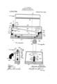
- FIG. 1 is a central longitudinalsectional view of an electric iron with my improved regulator applied thereto.
- Fig. 2 is a vertical sectional view taken on the line 2-2 of Fig. 1.
- Fig. 3 is a sectional view on the line 3-3 of Fig. 1.
- Fig. 4 is a detailed perspective view of an insulated arm employed in connection with is indicated an electric iron having a hood the-device.
- said hood having the usual handle-12- by which the iron may be manipulated.
- the heat bushin Embedded within the 11 is the heat bushin 'municated to the ironingsurface of the base and my improved regulator is adapted to cont-rolthe heating of the iron to prevent excessive heating thereof and destruction of the heating element as well as to regulate the temperature of the iron for use in connection with fabrics requiring different temperatures.
- an insulated block 14 Secured at one end of the hood 10 is an insulated block 14 in which one end of a rod 15 is rigidlysecured or embedded, said rod being constructed of some metal having a high coefficient of expansion, such as aluminum and being extended longitudinally for somev distance above the base 11-t0 a point adjacent the opposite end of the hood and freely received between the sides of an angular insulated arm 16 which is also scoured to one end of the hood opposite to the block 14.
- the arm 16 is provided with a vertical slot 17 and the bottom wall 18 unit 13 in the form of a resistance element which is adapted to support the free end of the rod 15 and to permit expansion thereof to be contacted by the end of the rod when the latter expands.
- the longer arm 21 of the lever is directed at an inclined position to the upper corner of the hood above the block 14 and is provided with a platinum cont-act point 22 adapted to be engaged by a contact point 23 also preferably formed of platinum at the lower end of a screw 24 which is threaded through an insulating 25 in the top of the hood 10 and which is provided with an insulated operating head 26 to protect the operator from shock of the electric current.
- a band spring 27 is adapted to engage the underface of the longer arm 21 to hold the contactv points in engagement with each other at all times when not overcome by.
- Feed and return wires 32 and 33 are connected to the screw 24 and the heat unit l3 respectively and the circuit is normally closed by contact of the arm 21 with the screw, thence to the base by the conductor 34 and returning by the .conductor 33 toany suitable source of electrio energy (not shown).
- the condenser pre vents arcing of current when the contact is broken and it is further evident that the adjustment of the screw 24 may be made to vary the gap or distance between the free end of the rod 15 and the short arm 20 ofthe bell crank lever, thereby enabling the operator to obtain any desired temperature.
- a heater of the class described comprising the combination with a heating element and a hood arranged thereon, of an expansible member insulated from and anchored at one end of the hood, a screw insulated from and adjustable in a bore in. the hood, a pivoted member arranged to be contacted by the expansible member, said plvoted member normally contacting with the screw and adapted to be disengaged therefrom by the longitudinal expansion of the expansible member, a condenser connected in circuit with the screw, the pivoted member and the heating element and means for" preventing lateral movement of the expans sible member.
Landscapes
- Irons (AREA)
Description
cnsnnns 1:. remains, or own. novnn, onto.
THEBMOSTATIO REGULATOR.
Specification of Letters Patent.
Patented Feb. 6, 1912.
Application filed April 27, 1911., Serial 11'0- 623,696.
To all whom it may concern:
'Be it known that 1, CHARLES E. Tnn'rnns,
- a citizen of .the United States, residing at Canal Dover, in the county of Tuscarawas, State of Ohio, have invented certain new and useful Improvements in Thermostatic Regulators; and I do hereby declare the fol- I lowing to be a full, clear, and exact description of the invention, such as will enable others skilled in the art to which it appertains to make and use the same.
' for regulating the heating of the iron or.
This invention relates to an improved thermostatic regulator for an electric iron or similar devices and the principal object of the invention is to provide a novel device varying the temperature thereof whereby the best results with different kinds of materials ironed may be procured and injury to the fabrics prevented.
Another object of the invention is to provide a novel regulating device adapted to prevent excessive heating of the iron or more especially the heating unit thereof and consequently preventing resultantdestruction of the heat unit.
Another object of the invention is to provide an improved regulating means in which continued excessive heating of the unit beyond a desirable temperature is prevented and so regulated that the amount of current consumed is greatly reduced, as the device prevents excessive heating of the iron.
With these and other objects in view.the invention consists of certain other combinations and arrangements of parts as will be hereinafter more fully described and claimed, it being a still further object to provide a device which will not be likely to get out of working order.
In the drawings :--Figure 1 is a central longitudinalsectional view of an electric iron with my improved regulator applied thereto. Fig. 2 is a vertical sectional view taken on the line 2-2 of Fig. 1. Fig. 3 is a sectional view on the line 3-3 of Fig. 1. Fig. 4 is a detailed perspective view of an insulated arm employed in connection with is indicated an electric iron having a hood the-device.
Referring to the drawings in detail, there ner, said hood having the usual handle-12- by which the iron may be manipulated.
Embedded within the 11 is the heat bushin 'municated to the ironingsurface of the base and my improved regulator is adapted to cont-rolthe heating of the iron to prevent excessive heating thereof and destruction of the heating element as well as to regulate the temperature of the iron for use in connection with fabrics requiring different temperatures.
Secured at one end of the hood 10 is an insulated block 14 in which one end of a rod 15 is rigidlysecured or embedded, said rod being constructed of some metal having a high coefficient of expansion, such as aluminum and being extended longitudinally for somev distance above the base 11-t0 a point adjacent the opposite end of the hood and freely received between the sides of an angular insulated arm 16 which is also scoured to one end of the hood opposite to the block 14. The arm 16 is provided with a vertical slot 17 and the bottom wall 18 unit 13 in the form of a resistance element which is adapted to support the free end of the rod 15 and to permit expansion thereof to be contacted by the end of the rod when the latter expands. The longer arm 21 of the lever is directed at an inclined position to the upper corner of the hood above the block 14 and is provided with a platinum cont-act point 22 adapted to be engaged by a contact point 23 also preferably formed of platinum at the lower end of a screw 24 which is threaded through an insulating 25 in the top of the hood 10 and which is provided with an insulated operating head 26 to protect the operator from shock of the electric current. A band spring 27 is adapted to engage the underface of the longer arm 21 to hold the contactv points in engagement with each other at all times when not overcome by. pressure on the short arm 20 and said spring is mounted upon an insulated terminal clock 28 also secured to one end of the hood above the block 14 and a condenser 29 is connected in circuit by the conductors 30 and 31 to the screw 24 and the bell crank lever at the terminal 19 so as to prevent arcing when the contact is broken. Feed and return wires 32 and 33 are connected to the screw 24 and the heat unit l3 respectively and the circuit is normally closed by contact of the arm 21 with the screw, thence to the base by the conductor 34 and returning by the .conductor 33 toany suitable source of electrio energy (not shown).
In the operation of the device when in use, and the current is flowing in the circuit just traced, the heat produced causes the'expansion of the rod 15 resulting in an elongation thereof and if excessive heat occurs, the contact of the free end of the rod with the short arm 20' will depress the 1011 er arm 21 and disengage the contacts 22 an 23, thus breaking the circuit through the heating element and allowing the iron to cool and therod to contract and permit the spring 27 to return thearm 21 to its normal position and automatically close the electric circuit through the heating element. It is also apparent that the condenser pre vents arcing of current when the contact is broken and it is further evident that the adjustment of the screw 24 may be made to vary the gap or distance between the free end of the rod 15 and the short arm 20 ofthe bell crank lever, thereby enabling the operator to obtain any desired temperature.
The advantages of a deviceof this character over the common expansive band which is rigidly secured at both ends and which is adapted to arch and break the electric contact are readily apparent, inasmuch as such devices could not be regulated to a certain standard and the adjustmentheretofore necessary rendered the iron Very expensive. In such devices, the expansionband finally becomes permanently afi'ected due to the frequent molecular strains produced when heated thereby rendering the sameinefiicient for use. Especial attention is also called to the fine range of adjustment which can be accomplished by varying the relative lengths of the arms 20 and 21 and the comparative slight movement necesfreely mounted at one end will resume its former length when cooled and no permanent change thus produced, thus rendering the parts capable of being standardized and the simplicity ofconstruction preventing any derangements thereof of parts.
I. claim a 1. Inan electric iron, the combination with a base and a heating element embedded therein; of a hood arranged upon the base, an expansiblerod secured at one end of the said hood, the other end being free, a lever pivoted adjacent the free end of the rod, one of the arms of the lever extending downwardly and spaced from the rod and the other arm extending'upwardly. in an inclined position, an adjustable terminal member, means to hold the inclined arm in contact therewith and an electric circuitincluding the adjustable member, the heat unit and the lever whereby expansion of the rod will contact with the downwardly extending end of the'lever to disconnect the other arm from the adjustable terminal member.
2. A heater of the class described comprising the combination with a heating element and a hood arranged thereon, of an expansible member insulated from and anchored at one end of the hood, a screw insulated from and adjustable in a bore in. the hood, a pivoted member arranged to be contacted by the expansible member, said plvoted member normally contacting with the screw and adapted to be disengaged therefrom by the longitudinal expansion of the expansible member, a condenser connected in circuit with the screw, the pivoted member and the heating element and means for" preventing lateral movement of the expans sible member.
In testimony whereof, I alfix my sigi1a ture,in presence of two witnesses.
. CHARLES E. TEETERS. Witnessesr FANNY F. TEETERs, RETINA 'I. OLnRoYn.
Priority Applications (1)
| Application Number | Priority Date | Filing Date | Title |
|---|---|---|---|
| US62369611A US1016795A (en) | 1911-04-27 | 1911-04-27 | Thermostatic regulator. |
Applications Claiming Priority (1)
| Application Number | Priority Date | Filing Date | Title |
|---|---|---|---|
| US62369611A US1016795A (en) | 1911-04-27 | 1911-04-27 | Thermostatic regulator. |
Publications (1)
| Publication Number | Publication Date |
|---|---|
| US1016795A true US1016795A (en) | 1912-02-06 |
Family
ID=3085098
Family Applications (1)
| Application Number | Title | Priority Date | Filing Date |
|---|---|---|---|
| US62369611A Expired - Lifetime US1016795A (en) | 1911-04-27 | 1911-04-27 | Thermostatic regulator. |
Country Status (1)
| Country | Link |
|---|---|
| US (1) | US1016795A (en) |
-
1911
- 1911-04-27 US US62369611A patent/US1016795A/en not_active Expired - Lifetime
Similar Documents
| Publication | Publication Date | Title |
|---|---|---|
| US3225820A (en) | Device for controlling temperature by heat conduction | |
| US2409420A (en) | Heating appliance | |
| US2067959A (en) | Thermostatic controlling apparatus | |
| US1016795A (en) | Thermostatic regulator. | |
| US2518595A (en) | Positive "off" thermostatic switch | |
| US2573404A (en) | Thermal control means for induction motors | |
| US1964732A (en) | Dilator | |
| US2184270A (en) | Heating device | |
| US2496917A (en) | Thermostatic switch | |
| US2851559A (en) | Thermostatic switch | |
| US3418454A (en) | Electric bedcover overtemperature control system | |
| US1963655A (en) | Thermostatic control | |
| US1612246A (en) | Thermal cut-out device | |
| US2557810A (en) | Thermostatic switch | |
| US2058390A (en) | Thermostatic switch | |
| US2740864A (en) | Precision thermostatic switch | |
| US2011610A (en) | Thermal switch | |
| US1855707A (en) | Control mechanism | |
| US1724425A (en) | Thermostat | |
| US1096916A (en) | Electrically-heated warming-pad. | |
| US2201115A (en) | Automatic flatiron, and thermostatic device for controlling the same | |
| US3078360A (en) | Electrical thermostatic switch | |
| US1903015A (en) | Electric heating pad and control therefor | |
| US1272469A (en) | Electrotherapeutic instrument. | |
| US3482195A (en) | Thermostatic control device for a three-phase type electrical apparatus |