US10167682B2 - Coupling mounted spin-through rod centralizer - Google Patents
Coupling mounted spin-through rod centralizer Download PDFInfo
- Publication number
- US10167682B2 US10167682B2 US14/879,148 US201514879148A US10167682B2 US 10167682 B2 US10167682 B2 US 10167682B2 US 201514879148 A US201514879148 A US 201514879148A US 10167682 B2 US10167682 B2 US 10167682B2
- Authority
- US
- United States
- Prior art keywords
- coupling
- stator
- length
- rod string
- rod
- Prior art date
- Legal status (The legal status is an assumption and is not a legal conclusion. Google has not performed a legal analysis and makes no representation as to the accuracy of the status listed.)
- Active, expires
Links
- 230000008878 coupling Effects 0.000 title claims abstract description 72
- 238000010168 coupling process Methods 0.000 title claims abstract description 72
- 238000005859 coupling reaction Methods 0.000 title claims abstract description 72
- 238000004519 manufacturing process Methods 0.000 claims description 9
- 229910000831 Steel Inorganic materials 0.000 abstract description 3
- 239000010959 steel Substances 0.000 abstract description 3
- 230000008901 benefit Effects 0.000 description 3
- 239000004033 plastic Substances 0.000 description 3
- 239000012530 fluid Substances 0.000 description 2
- 238000000034 method Methods 0.000 description 2
- 230000003247 decreasing effect Effects 0.000 description 1
- 238000007373 indentation Methods 0.000 description 1
- 238000009434 installation Methods 0.000 description 1
- 238000005304 joining Methods 0.000 description 1
- 239000000463 material Substances 0.000 description 1
- 230000004048 modification Effects 0.000 description 1
- 238000012986 modification Methods 0.000 description 1
- 230000000704 physical effect Effects 0.000 description 1
- 238000002360 preparation method Methods 0.000 description 1
- 230000008569 process Effects 0.000 description 1
- 230000000452 restraining effect Effects 0.000 description 1
- 239000003381 stabilizer Substances 0.000 description 1
- 239000000126 substance Substances 0.000 description 1
- 229920001169 thermoplastic Polymers 0.000 description 1
- 239000004416 thermosoftening plastic Substances 0.000 description 1
Images


Classifications
-
- E—FIXED CONSTRUCTIONS
- E21—EARTH OR ROCK DRILLING; MINING
- E21B—EARTH OR ROCK DRILLING; OBTAINING OIL, GAS, WATER, SOLUBLE OR MELTABLE MATERIALS OR A SLURRY OF MINERALS FROM WELLS
- E21B17/00—Drilling rods or pipes; Flexible drill strings; Kellies; Drill collars; Sucker rods; Cables; Casings; Tubings
- E21B17/10—Wear protectors; Centralising devices, e.g. stabilisers
- E21B17/1071—Wear protectors; Centralising devices, e.g. stabilisers specially adapted for pump rods, e.g. sucker rods
-
- E—FIXED CONSTRUCTIONS
- E21—EARTH OR ROCK DRILLING; MINING
- E21B—EARTH OR ROCK DRILLING; OBTAINING OIL, GAS, WATER, SOLUBLE OR MELTABLE MATERIALS OR A SLURRY OF MINERALS FROM WELLS
- E21B17/00—Drilling rods or pipes; Flexible drill strings; Kellies; Drill collars; Sucker rods; Cables; Casings; Tubings
- E21B17/02—Couplings; joints
- E21B17/04—Couplings; joints between rod or the like and bit or between rod and rod or the like
- E21B17/042—Threaded
- E21B17/043—Threaded with locking means
Definitions
- the present invention relates to improvements in spin-through drive rod centralizers, and in particular spin-through centralizers mounted at the connection between adjacent rods, that are used to rotationally drive a downhole pump to retrieve and deliver to the surface production fluids from subterranean deposits.
- Rod centralizers of which spin-through centralizers are one type, are used principally to keep a rotating rod string from contacting the inner wall of the production tubing.
- the centralizers are also used to maintain rotational stability. Unstable rotation is undesirable when the amplitude of the unstable motion is greater than the internal diameter of the tubing, causing rod-tubing contact. The unstable motion of the rod also increases the likelihood of fatigue failure of the rod string.
- a rod rotating around its principal axis will turn smoothly up to a critical rotational speed, which is a function of the diameter of the rod, physical properties of the rod material, and the cross-sectional shape, the distance between supports or bearings, and the axial tension the rod is experiencing.
- a critical rotational speed which is a function of the diameter of the rod, physical properties of the rod material, and the cross-sectional shape, the distance between supports or bearings, and the axial tension the rod is experiencing.
- the natural stiffness of the rod is great enough to overcome the centrifugal force of the rotation.
- the centrifugal force increases with the square of the rotational speed, while the stiffness remains unchanged, and, eventually, the tendency of the rod to swing out of the stable, linear rotational axis will be greater than the stiffness can resist, and the rod will begin rotating unstably.
- spin-through centralizers There are two principal types of spin-through centralizers currently commercially available. The more common consists of a vaned plastic stator that is fitted over a thermo-plastic sleeve molded on to the body of the rod. The advantage of this type of spin-through centralizer is that any number of them can be applied to the rod, as required by the rotational stability needs. In low-tension portions of the rod string in GCP applications, for instance, as many as four centralizers per 25′ rod may be required.
- the other type of spin-through centralizer is mounted only at the connection between rods.
- the type currently commercially available consists of a short, steel shaft that is threaded at both ends, with a section between the threaded portions that forms the journal, onto which the plastic stator is mounted.
- the threaded journal shaft is attached to the two adjacent rods via two standard female rod couplings.
- the outer diameter of the couplings is slightly larger than the outer diameter of the shaft journal surface, so the stator cannot move axially off the journal during rod rotation.
- connection mounted spin-through centralizer described above has several drawbacks, principal of which is cost.
- the extra length of the connection due to the threaded journal shaft requires that the rod connection so equipped must be made up by hand rather than via mechanical rod tongs, a time consuming process.
- the connection itself is not as strong as a conventional connection due to the reduced shoulder area between the threaded journal shaft and the couplings.
- the present invention is also a connection-mounted spin-through centralizer, but addresses all the shortcomings of the currently available type, by doing away with the threaded journal shaft and the additional coupling, allowing the rod connections to be made-up with existing equipment.
- the resulting connection of the present invention is also equal to the strength of a standard connection and, due to its simplicity, can be produced at significantly reduced cost compared to the currently available type.
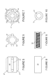
- FIG. 1 shows a side view of a conventional rod connection prior to make-up
- FIG. 8 shows a side view of a standard internally threaded female coupling
- FIG. 9 shows an axial cross-section through a standard coupling
- FIG. 14 shows the components of the second embodiment of the present invention, prior to rod connection make-up
- FIG. 16 shows an alternative configuration of the female threaded coupling of the second embodiment
- the outer surface of shoulders 17 and 18 which contact the ends of female threaded coupling (heretofore simply referred to as “coupling”) 15 when the connection is made-up, are finely machined, as are the ends of the coupling.
- the two male threaded pins 21 and 22 are screwed into coupling 15 , the rotational direction shown by arrows A and A′, with the connection made up against shoulders 17 and 18 , putting the male threaded pins 21 and 22 into tension, and joining the two rods 11 and 12 , as shown in FIG. 2 .
- Note the connected rods in FIG. 2 are shown within a length of production tubing 19 .
- FIGS. 11 through 16 A second embodiment of the present invention, which addresses this disassembly issue, is shown in FIGS. 11 through 16 .
- the female coupling 31 of this alternative embodiment is shown in FIGS. 11 and 12 .
- coupling 31 has a machined shoulder 32 that is larger in outside diameter than the main body 34 of coupling 31 .
- This shoulder serves two purposes. First, it takes the place of one of the retaining washers, in this instance, washer 25 , and, secondly, the larger diameter of the shoulder 32 provides a surface for a pipe wrench to grip while removing the coupling 31 from the rod pin during disassembly.
- the smooth bearing outer surface of the main body 34 of coupling 31 is therefore not touched by the wrench jaws during disassembly, so the coupling can be reused without requiring refinishing.
Landscapes
- Engineering & Computer Science (AREA)
- Life Sciences & Earth Sciences (AREA)
- Geology (AREA)
- Mining & Mineral Resources (AREA)
- Mechanical Engineering (AREA)
- Physics & Mathematics (AREA)
- Environmental & Geological Engineering (AREA)
- Fluid Mechanics (AREA)
- General Life Sciences & Earth Sciences (AREA)
- Geochemistry & Mineralogy (AREA)
- Mutual Connection Of Rods And Tubes (AREA)
- Earth Drilling (AREA)
Abstract
A spin-through rod centralizer consisting of a stator mounted on the rod coupling which provides the bearing surface for rotation of the coupling within the stator. The stator is restrained from such axial movement by two steel “washers” that are captured between the rod shoulders and the coupling when the connection between two rods is made up. The washers are slightly larger in diameter than the coupling and thereby keep the stator located on the coupling, yet do not restrict the relative rotation between the coupling and the stator. An alternative configuration uses a coupling with a shoulder at one end that acts as one of the “washers” to restrain the stator from axial movement.
Description
Applicant claims the benefits of provisional application Ser. No. 62/094,215, filed Dec. 19, 2014. The present invention relates to improvements in spin-through drive rod centralizers, and in particular spin-through centralizers mounted at the connection between adjacent rods, that are used to rotationally drive a downhole pump to retrieve and deliver to the surface production fluids from subterranean deposits.
Rod centralizers, of which spin-through centralizers are one type, are used principally to keep a rotating rod string from contacting the inner wall of the production tubing. In some rotating rod applications, such as geared centrifugal pump (GCP) applications, particularly where rod string tension is low, the centralizers are also used to maintain rotational stability. Unstable rotation is undesirable when the amplitude of the unstable motion is greater than the internal diameter of the tubing, causing rod-tubing contact. The unstable motion of the rod also increases the likelihood of fatigue failure of the rod string.
A rod rotating around its principal axis will turn smoothly up to a critical rotational speed, which is a function of the diameter of the rod, physical properties of the rod material, and the cross-sectional shape, the distance between supports or bearings, and the axial tension the rod is experiencing. During stable rotation, the natural stiffness of the rod is great enough to overcome the centrifugal force of the rotation. However, as the rotational speed increases, the centrifugal force increases with the square of the rotational speed, while the stiffness remains unchanged, and, eventually, the tendency of the rod to swing out of the stable, linear rotational axis will be greater than the stiffness can resist, and the rod will begin rotating unstably.
The effective stiffness of the rod can be increased by decreasing the unsupported length of rod, by installing bearings, or rotational supports, at closer spacing along the rod's length. This will increase the stable rotational speed. For rods, these supports, or bearings, can be simple centralizers, which are fixed to and rotate with the rod, or they can be spin-through type centralizers, which consist of a stator that stays rotationally fixed within the tubing, with the rod passing through a central bore of the stator, and rotating therein. The present invention disclosed and described herein is of the spin-through type.
There are two principal types of spin-through centralizers currently commercially available. The more common consists of a vaned plastic stator that is fitted over a thermo-plastic sleeve molded on to the body of the rod. The advantage of this type of spin-through centralizer is that any number of them can be applied to the rod, as required by the rotational stability needs. In low-tension portions of the rod string in GCP applications, for instance, as many as four centralizers per 25′ rod may be required.
The other type of spin-through centralizer is mounted only at the connection between rods. The type currently commercially available consists of a short, steel shaft that is threaded at both ends, with a section between the threaded portions that forms the journal, onto which the plastic stator is mounted. The threaded journal shaft is attached to the two adjacent rods via two standard female rod couplings. The outer diameter of the couplings is slightly larger than the outer diameter of the shaft journal surface, so the stator cannot move axially off the journal during rod rotation.
This connection mounted spin-through centralizer described above has several drawbacks, principal of which is cost. In addition, the extra length of the connection due to the threaded journal shaft requires that the rod connection so equipped must be made up by hand rather than via mechanical rod tongs, a time consuming process. Also, the connection itself is not as strong as a conventional connection due to the reduced shoulder area between the threaded journal shaft and the couplings.
The present invention is also a connection-mounted spin-through centralizer, but addresses all the shortcomings of the currently available type, by doing away with the threaded journal shaft and the additional coupling, allowing the rod connections to be made-up with existing equipment. The resulting connection of the present invention is also equal to the strength of a standard connection and, due to its simplicity, can be produced at significantly reduced cost compared to the currently available type.
The utility, strength and low cost of the proposed spin-through centralizer of the present invention arises from the fact that it utilizes the components and function of a conventional rod connection. FIGS. 1 and 2 show the components and configuration of a conventional rod connection. FIG. 1 shows the adjacent ends of two rods 11 and 12 to be connected. At both ends of every rod, which are typically 25 feet in length, there is a male threaded pin, a shoulder against which the connection is made, and a wrench flat that allows gripping the rods for make-up of the threaded connections. These three components of rod 11 are threaded pin 21, shoulder 17, and wrench flat 13. Adjacent rod 12 is similarly equipped, with threaded pin 22, shoulder 18 and wrench flat 14. The outer surface of shoulders 17 and 18, which contact the ends of female threaded coupling (heretofore simply referred to as “coupling”) 15 when the connection is made-up, are finely machined, as are the ends of the coupling. The two male threaded pins 21 and 22 are screwed into coupling 15, the rotational direction shown by arrows A and A′, with the connection made up against shoulders 17 and 18, putting the male threaded pins 21 and 22 into tension, and joining the two rods 11 and 12, as shown in FIG. 2 . Note the connected rods in FIG. 2 are shown within a length of production tubing 19.
The vanes 27 act to center the stator and, hence, the rod connection inside the tubing 19, while allowing fluid to flow past the connection. The outside diameter of the vanes 27 is slightly smaller than the inside diameter of the tubing 19 to allow ease of installation.
The first embodiment of the present invention, shown in FIGS. 3 through 10 , utilizes two washers, 25 and 26, situated between coupling 15 and the adjacent shoulders 17 and 18, to axially retain the stator 23 in its position over coupling 15. One of the advantages of this embodiment is a conventional rod connection can be easily converted to a spin-through stabilizer via a couple of washers 25, and 26, and a stator 23, while utilizing the same type of female coupling used in conventional rod connections. A potential disadvantage of this first embodiment, however, is in the disassembly of the rod connections.
Usually, a conventional rod connection is made without holding or rotating the female coupling—only the rods are rotated. The make-up procedure of the first embodiment, likewise, does not require manipulating coupling 15. However, when the rod string is pulled from the well and disassembled, the couplings will remain on one or the other of the formerly joined rod pins. The only way the coupling can be removed from that rod pin is by restraining the rod via the wrench flat (e.g. 13), and applying a pipe wrench to the external surface of the coupling to break the connection. The pipe wrench jaws can deeply mar the outer surface of the coupling. This surface damage would render the coupling unsuitable for reuse without refinishing.
A second embodiment of the present invention, which addresses this disassembly issue, is shown in FIGS. 11 through 16 . The female coupling 31 of this alternative embodiment is shown in FIGS. 11 and 12 . Unlike coupling 15 of the first embodiment, which has a constant outside diameter over its entire length, coupling 31 has a machined shoulder 32 that is larger in outside diameter than the main body 34 of coupling 31. This shoulder serves two purposes. First, it takes the place of one of the retaining washers, in this instance, washer 25, and, secondly, the larger diameter of the shoulder 32 provides a surface for a pipe wrench to grip while removing the coupling 31 from the rod pin during disassembly. The smooth bearing outer surface of the main body 34 of coupling 31 is therefore not touched by the wrench jaws during disassembly, so the coupling can be reused without requiring refinishing.
A minor modification of the threaded female coupling of the second embodiment is shown in FIGS. 16 through 18 , where the shoulder 36 is fitted with machined wrench flats 37, allowing coupling 35 to be gripped with a conventional wrench, rather than a pipe wrench, for removal from the rods during disassembly.
It will be appreciated that those skilled in the art, upon reading this detailed description, may think of some variations in structure and form, such variations are within the contemplation of the invention as described and claimed in the following:
Claims (2)
1. A drive rod string centralizer to position a connection between a first rod string and a second rod string within a production tubing, the drive rod string centralizer comprising:
a stator, said stator being comprised of a cylindrical body having a longitudinal length, said cylindrical body having an external diameter less than the internal diameter of said production tubing, and having a smooth central bore and several, equal length vanes extending radially from said cylindrical body, the radial extent of said vanes being less than the internal diameter of said production tubing;
a cylindrical coupling, said cylindrical coupling having a central bore along its longitudinal length, said central bore being equipped with female threads on the interior surface, a first length of the outer cylindrical surface of said coupling having an external diameter less than then the internal diameter of the central bore of said stator, said first length being greater than the length of said stator, and a second length of the outer cylindrical surface having an external diameter greater than the internal diameter of said central bore of said stator,
a thin circular disc, said thin circular disc having an outer diameter greater than the inner diameter of said central bore of said stator, and having a central bore;
wherein said central bore of said circular disc has an inner diameter greater than the outer diameter of threads of threaded pins on said ends of each of said first rod string and said second rod string;
wherein said first length of said coupling is inserted into said stator central bore;
wherein said first rod string and said second rod string are aligned axially with one another and with said coupling and stator, said circular disc being disposed between a shoulder of said first rod string or said second rod string and the end of said first length of said coupling;
wherein said rods are rotated in such a manner as to cause said threaded pins to thread into said coupling until said coupling and circular disc are firmly held between said shoulders.
2. The drive rod string centralizer of claim 1 , wherein said second length of said cylindrical coupling has flat surfaces machined or formed into the outer surface of said second length of said cylindrical coupling tangentially to the longitudinal axis of said cylindrical coupling.
Priority Applications (1)
| Application Number | Priority Date | Filing Date | Title |
|---|---|---|---|
| US14/879,148 US10167682B2 (en) | 2014-12-19 | 2015-10-09 | Coupling mounted spin-through rod centralizer |
Applications Claiming Priority (2)
| Application Number | Priority Date | Filing Date | Title |
|---|---|---|---|
| US201462094215P | 2014-12-19 | 2014-12-19 | |
| US14/879,148 US10167682B2 (en) | 2014-12-19 | 2015-10-09 | Coupling mounted spin-through rod centralizer |
Publications (2)
| Publication Number | Publication Date |
|---|---|
| US20160177635A1 US20160177635A1 (en) | 2016-06-23 |
| US10167682B2 true US10167682B2 (en) | 2019-01-01 |
Family
ID=56128824
Family Applications (1)
| Application Number | Title | Priority Date | Filing Date |
|---|---|---|---|
| US14/879,148 Active 2037-02-01 US10167682B2 (en) | 2014-12-19 | 2015-10-09 | Coupling mounted spin-through rod centralizer |
Country Status (1)
| Country | Link |
|---|---|
| US (1) | US10167682B2 (en) |
Cited By (2)
| Publication number | Priority date | Publication date | Assignee | Title |
|---|---|---|---|---|
| US11828115B1 (en) * | 2021-07-12 | 2023-11-28 | Swm International, Llc | Systems and apparatus for increasing the outer diameter of a downhole tool string and methods of assembly and use thereof |
| US11976521B2 (en) | 2019-08-01 | 2024-05-07 | Chevron U.S.A. Inc. | High speed rotor dynamics centralizer |
Families Citing this family (4)
| Publication number | Priority date | Publication date | Assignee | Title |
|---|---|---|---|---|
| AU201812056S (en) * | 2018-04-09 | 2018-05-01 | Cobalt Extreme Pty Ltd | A rod coupler |
| AU201815446S (en) * | 2018-09-10 | 2018-10-09 | Cobalt Extreme Pty Ltd | A Rod Coupler |
| US11306548B2 (en) * | 2018-12-13 | 2022-04-19 | Harrier Technologies, Inc. | Full tubing inner-diameter spin-through rod centralizers |
| USD954754S1 (en) * | 2020-02-28 | 2022-06-14 | Cobalt Extreme Pty Ltd | Rod coupler |
Citations (8)
| Publication number | Priority date | Publication date | Assignee | Title |
|---|---|---|---|---|
| US3049382A (en) * | 1960-12-20 | 1962-08-14 | Liberty Mfg Company Of Texas | Anti-friction sucker rod coupling |
| US4823456A (en) * | 1987-10-26 | 1989-04-25 | Gray Kenneth W | Method for protecting sucker rod couplings from abrasion and corrosion |
| US4905760A (en) * | 1987-10-26 | 1990-03-06 | Ico, Inc. | Sucker rod coupling with protective coating |
| US4919202A (en) * | 1989-02-08 | 1990-04-24 | Carl Clintberg | Sucker rod guide bearing |
| US5950744A (en) * | 1997-10-14 | 1999-09-14 | Hughes; W. James | Method and apparatus for aligning drill pipe and tubing |
| US20080035329A1 (en) * | 2006-08-14 | 2008-02-14 | Carstensen Kenneth J | Interconnect rod for sucker rod string |
| US20120186818A1 (en) * | 2009-08-31 | 2012-07-26 | Arnold Wollmann | Sucker Rod Coupling and Method of Wear Prevention in Driven Rotation of a Sucker Rod String in Production Tubing |
| US20120193089A1 (en) * | 2011-02-02 | 2012-08-02 | Plainsman Manufacturing Inc. | Sucker Rod Centralizer |
-
2015
- 2015-10-09 US US14/879,148 patent/US10167682B2/en active Active
Patent Citations (8)
| Publication number | Priority date | Publication date | Assignee | Title |
|---|---|---|---|---|
| US3049382A (en) * | 1960-12-20 | 1962-08-14 | Liberty Mfg Company Of Texas | Anti-friction sucker rod coupling |
| US4823456A (en) * | 1987-10-26 | 1989-04-25 | Gray Kenneth W | Method for protecting sucker rod couplings from abrasion and corrosion |
| US4905760A (en) * | 1987-10-26 | 1990-03-06 | Ico, Inc. | Sucker rod coupling with protective coating |
| US4919202A (en) * | 1989-02-08 | 1990-04-24 | Carl Clintberg | Sucker rod guide bearing |
| US5950744A (en) * | 1997-10-14 | 1999-09-14 | Hughes; W. James | Method and apparatus for aligning drill pipe and tubing |
| US20080035329A1 (en) * | 2006-08-14 | 2008-02-14 | Carstensen Kenneth J | Interconnect rod for sucker rod string |
| US20120186818A1 (en) * | 2009-08-31 | 2012-07-26 | Arnold Wollmann | Sucker Rod Coupling and Method of Wear Prevention in Driven Rotation of a Sucker Rod String in Production Tubing |
| US20120193089A1 (en) * | 2011-02-02 | 2012-08-02 | Plainsman Manufacturing Inc. | Sucker Rod Centralizer |
Cited By (3)
| Publication number | Priority date | Publication date | Assignee | Title |
|---|---|---|---|---|
| US11976521B2 (en) | 2019-08-01 | 2024-05-07 | Chevron U.S.A. Inc. | High speed rotor dynamics centralizer |
| US12091922B2 (en) | 2019-08-01 | 2024-09-17 | Chevron U.S.A. Inc. | Artificial lift systems utilizing high speed centralizers |
| US11828115B1 (en) * | 2021-07-12 | 2023-11-28 | Swm International, Llc | Systems and apparatus for increasing the outer diameter of a downhole tool string and methods of assembly and use thereof |
Also Published As
| Publication number | Publication date |
|---|---|
| US20160177635A1 (en) | 2016-06-23 |
Similar Documents
| Publication | Publication Date | Title |
|---|---|---|
| US10167682B2 (en) | Coupling mounted spin-through rod centralizer | |
| US9303466B2 (en) | Sucker rod centralizer | |
| US8863834B2 (en) | Friction reducing wear band and method of coupling a wear band to a tubular | |
| US20120186818A1 (en) | Sucker Rod Coupling and Method of Wear Prevention in Driven Rotation of a Sucker Rod String in Production Tubing | |
| US20210293096A1 (en) | Centralizer | |
| CN105781444B (en) | One kind subtracts torsion drop resistance stabilizer | |
| US20160362944A1 (en) | Smooth bore collar | |
| CN204344076U (en) | A kind of efficient brush cleaning workover tool | |
| US20170030148A1 (en) | Locking Nut With A Directional Coupling Mechanism | |
| CN106907115A (en) | A kind of roller type antifriction pipe nipple | |
| CN204299490U (en) | A kind of universal Anti-drop centralizer | |
| US1745310A (en) | Pump-rod swivel | |
| US2011036A (en) | Casing roller | |
| CN103418700B (en) | Swollen head group part | |
| CN203978310U (en) | Twist joint falls in anti-attrition | |
| CN205714019U (en) | One subtracts torsion fall resistance regulator | |
| CN201310306Y (en) | Stabilizer for rotary oil pipe | |
| US1574187A (en) | Swivel joint | |
| CN205036313U (en) | Antifriction connects | |
| CN203796184U (en) | Resistance and torque reducing device for drill stem | |
| CN105257227B (en) | a rigid centralizer | |
| CN205423519U (en) | Connecting piece and notebook computer rotate | |
| CN204326998U (en) | Pin nylon centralising device | |
| CN110439483A (en) | Sleeve connection device and sleeve connection method | |
| CN204871161U (en) | Novel steering column |
Legal Events
| Date | Code | Title | Description |
|---|---|---|---|
| AS | Assignment |
Owner name: HARRIER TECHNOLOGIES, INC., CONNECTICUT Free format text: ASSIGNMENT OF ASSIGNORS INTEREST;ASSIGNOR:MORROW, WILLIAM BRUCE;REEL/FRAME:041175/0468 Effective date: 20161215 |
|
| STCF | Information on status: patent grant |
Free format text: PATENTED CASE |
|
| MAFP | Maintenance fee payment |
Free format text: PAYMENT OF MAINTENANCE FEE, 4TH YR, SMALL ENTITY (ORIGINAL EVENT CODE: M2551); ENTITY STATUS OF PATENT OWNER: SMALL ENTITY Year of fee payment: 4 |