US10163181B2 - Method and system for joint evaluation of a medical image dataset - Google Patents
Method and system for joint evaluation of a medical image dataset Download PDFInfo
- Publication number
- US10163181B2 US10163181B2 US14/973,202 US201514973202A US10163181B2 US 10163181 B2 US10163181 B2 US 10163181B2 US 201514973202 A US201514973202 A US 201514973202A US 10163181 B2 US10163181 B2 US 10163181B2
- Authority
- US
- United States
- Prior art keywords
- application
- segment
- data
- observer
- presenter
- Prior art date
- Legal status (The legal status is an assumption and is not a legal conclusion. Google has not performed a legal analysis and makes no representation as to the accuracy of the status listed.)
- Active, expires
Links
Images


Classifications
-
- G—PHYSICS
- G16—INFORMATION AND COMMUNICATION TECHNOLOGY [ICT] SPECIALLY ADAPTED FOR SPECIFIC APPLICATION FIELDS
- G16Z—INFORMATION AND COMMUNICATION TECHNOLOGY [ICT] SPECIALLY ADAPTED FOR SPECIFIC APPLICATION FIELDS, NOT OTHERWISE PROVIDED FOR
- G16Z99/00—Subject matter not provided for in other main groups of this subclass
-
- G—PHYSICS
- G06—COMPUTING OR CALCULATING; COUNTING
- G06T—IMAGE DATA PROCESSING OR GENERATION, IN GENERAL
- G06T1/00—General purpose image data processing
- G06T1/20—Processor architectures; Processor configuration, e.g. pipelining
-
- G06F19/00—
-
- G—PHYSICS
- G06—COMPUTING OR CALCULATING; COUNTING
- G06T—IMAGE DATA PROCESSING OR GENERATION, IN GENERAL
- G06T11/00—Two-dimensional [2D] image generation
- G06T11/60—Creating or editing images; Combining images with text
-
- G—PHYSICS
- G06—COMPUTING OR CALCULATING; COUNTING
- G06T—IMAGE DATA PROCESSING OR GENERATION, IN GENERAL
- G06T5/00—Image enhancement or restoration
- G06T5/20—Image enhancement or restoration using local operators
-
- G—PHYSICS
- G06—COMPUTING OR CALCULATING; COUNTING
- G06T—IMAGE DATA PROCESSING OR GENERATION, IN GENERAL
- G06T7/00—Image analysis
- G06T7/0002—Inspection of images, e.g. flaw detection
- G06T7/0012—Biomedical image inspection
-
- G—PHYSICS
- G16—INFORMATION AND COMMUNICATION TECHNOLOGY [ICT] SPECIALLY ADAPTED FOR SPECIFIC APPLICATION FIELDS
- G16H—HEALTHCARE INFORMATICS, i.e. INFORMATION AND COMMUNICATION TECHNOLOGY [ICT] SPECIALLY ADAPTED FOR THE HANDLING OR PROCESSING OF MEDICAL OR HEALTHCARE DATA
- G16H40/00—ICT specially adapted for the management or administration of healthcare resources or facilities; ICT specially adapted for the management or operation of medical equipment or devices
- G16H40/60—ICT specially adapted for the management or administration of healthcare resources or facilities; ICT specially adapted for the management or operation of medical equipment or devices for the operation of medical equipment or devices
- G16H40/63—ICT specially adapted for the management or administration of healthcare resources or facilities; ICT specially adapted for the management or operation of medical equipment or devices for the operation of medical equipment or devices for local operation
-
- G—PHYSICS
- G16—INFORMATION AND COMMUNICATION TECHNOLOGY [ICT] SPECIALLY ADAPTED FOR SPECIFIC APPLICATION FIELDS
- G16H—HEALTHCARE INFORMATICS, i.e. INFORMATION AND COMMUNICATION TECHNOLOGY [ICT] SPECIALLY ADAPTED FOR THE HANDLING OR PROCESSING OF MEDICAL OR HEALTHCARE DATA
- G16H80/00—ICT specially adapted for facilitating communication between medical practitioners or patients, e.g. for collaborative diagnosis, therapy or health monitoring
-
- G—PHYSICS
- G06—COMPUTING OR CALCULATING; COUNTING
- G06T—IMAGE DATA PROCESSING OR GENERATION, IN GENERAL
- G06T2200/00—Indexing scheme for image data processing or generation, in general
- G06T2200/24—Indexing scheme for image data processing or generation, in general involving graphical user interfaces [GUIs]
Definitions
- the present embodiments relate to joint evaluation of a medical image dataset on at least two data processing devices that are connected via a data transmission network, a corresponding system.
- the prior art enables a plurality of users to see and assess the same dataset on respective local data processing devices simultaneously, using respective local applications at the same time independently of one another.
- the assessments respectively generated by the individual operators are not then visible, or only visible with a considerable time delay, to the respectively other users, with the result that an effective exchange of information is not possible.
- the same image dataset is processed independently by a plurality of users, there is a high risk that the work results of one user will be overwritten by the actions of another user and will thus be lost.
- One of the users may make his or her screen content (e.g., the information displayed on his or her screen) available to another data processing device by using remote screen technology.
- distribution of the screen display using remote screen technology may entail considerable loss of quality of the image data to be displayed (e.g., if the data processing devices concerned have screens or other visual display units with different form factors). For this reason, usually only the user who is carrying out distribution can and may generate assessments in the system, which in turn counteracts effective collaboration. Similar problems also occur with conventional applications for online conferences or webinars.
- the present embodiments may obviate one or more of the drawbacks or limitations in the related art.
- a method and an associated system that efficiently support joint evaluation of a medical image dataset on a plurality of data processing devices connected via a data transmission network are provided.
- the image datasets that are evaluated in the course of the method or by the system may optionally be single images with two-dimensional image information, image stacks having a plurality of in each case two-dimensional individual images (e.g., layers), three-dimensional image data (e.g., volumes), or moving image sequences with two-dimensional or three-dimensional image information.
- the system is configured to support the evaluation of image datasets of various kinds.
- One or more of the present embodiments take as a starting point a data processing system having at least two data processing devices that are connected via a data transmission network for the mutual exchange of data.
- the term “data processing device” e.g., device
- At least one of the devices may in this case be a personal computer or a workstation that is equipped with one or more screens as visual display units and with keyboard, mouse etc. as input units.
- at least one of the devices is formed by a notebook, tablet, personal digital assistant (PDA) or smartphone.
- PDA personal digital assistant
- the system may contain only devices of the same type. Usually, however, the system will include any combination of devices of various kinds, as desired.
- the system includes as the devices a personal computer and a tablet.
- the data transmission network is, for example, a local area network (LAN) that includes wired and/or wireless data transmission circuits.
- LAN local area network
- the data transmission network may also be composed of a plurality of subnetworks based on like or different data transmission standards (e.g., two LANs connected over the Internet).
- the devices used within the scope of the method are in this case configured for evaluation of medical image datasets in that in each of these devices at least one application (e.g., software application) that has a graphical user interface (GUI) having at least one segment for displaying a view of a medical image dataset is implemented.
- application e.g., software application
- GUI graphical user interface
- view may designate a digital, two-dimensional image that has been derived from an underlying medical image dataset and may be displayed directly on the screen.
- the view derived therefrom is, for example, an extract of this image information that has been compressed (e.g., in terms of pixel resolution), rotated, re-colored, smoothed (e.g., denoised) and/or processed in some other way.
- the view derived therefrom typically reproduces a processed (as described above) extract of a particular layer of this image stack.
- the view may also be derived from a combination (e.g., an additive or subtractive overlaying) of a plurality of layers.
- the view derived therefrom represents, for example, a section through the three-dimensional image information of the image dataset or an image scene generated by volume rendering.
- segment designates a software module that, within the context of the GUI, serves to display the view on a screen or on the other visual display units of the device.
- the segment typically takes the form of a frame or window inside which the view is displayed.
- the segment typically contains a number of tools (e.g., software tools), such as drop-down menus, by which a user interacting with the GUI may bring about actions for manipulating the image data being displayed.
- the GUI of each application may contain one or more of these segments. For example, at least one of the applications is set up such that, by user interaction with the GUI, any number of segments as desired may be reversibly opened and closed again.
- an image processing pipeline For deriving the view to be displayed in the segment from the underlying image dataset, an image processing pipeline is associated with each segment.
- image processing pipeline e.g., pipeline
- Each filter performs a particular processing step on the data of the image dataset.
- filter designates a software module that contains, as the input variable, original data or data of the image dataset that has been partially processed (e.g., by a filter upstream, where appropriate) and outputs further processed data of the image dataset to the segment for display, or where appropriate, to a filter downstream for further processing.
- Examples of the filters of the pipeline are, for example, an xy filter for centering an image extract to be displayed, in relation to an image plane of the underlying image dataset, a zoom filter for enlarging or reducing the image extract that is to be displayed as a view, a color filter for re-coloring the image information (e.g., color filter may cover anatomical filters, such as bone filters or soft tissue filters, that eliminate from the image information, or highlight therein, particular color value ranges of the image information corresponding, as is known from experience, to particular anatomical structures such as soft tissue or bone), and a rotary filter that rotates the image information about a predetermined angle within the image plane.
- an xy filter for centering an image extract to be displayed, in relation to an image plane of the underlying image dataset
- a zoom filter for enlarging or reducing the image extract that is to be displayed as a view
- a color filter for re-coloring the image information e.g., color filter may cover anatomical filters
- Filters of the types described above may also be represented a plurality of times within the pipeline.
- a plurality of the functions described above e.g., xy centering and zoom
- the pipeline takes a form such that during the running time of the application individual filters of the pipeline may be brought into the pipeline, automatically or by user interaction with the GUI, or may be removed from the pipeline.
- the view created from the underlying image data is generated in a multi-stage process, in that the image data runs through the filters that are connected one after the other and in so doing is successively further processed.
- a first application is performed in a first device, and a second application is performed in a second device.
- partially processed data from the image dataset to be evaluated is decoupled from the pipeline (e.g., image processing pipeline) of the segment (or, where applicable, of one of a plurality of segments) of the first application and is transferred to the second application.
- the associated segment of the first application is designated the “presenter segment” below.
- the image processing pipeline of this presenter segment from which the partially processed data is decoupled is accordingly designated a “presenter pipeline” below.
- the decoupled data is received by the second application and at the second application is coupled to the image processing pipeline of the segment there (or, where applicable, of one of a plurality of segments of the second application) for preparing the view.
- the relevant segment of the second application is also designated the “observer segment” below.
- the image processing pipeline of the observer segment to which the partially processed data is coupled is designated the “observer pipeline”.
- the decoupling and coupling process described above is performed in that, in the course of the multi-stage processing process that is carried out by the presenter pipeline, a copy of the partially processed data is generated and is processed further in the observer pipeline (e.g., where appropriate, instead of other data that was processed there hitherto) to give the view displayed in the observer segment.
- the partially processed data is also processed further in the presenter pipeline to generate the view to be displayed in the presenter segment.
- the multi-stage processing process for generating the views for the presenter segment and the observer segment is carried out in a first section in a single channel in the presenter pipeline and is then split into a first processing branch and a second processing branch.
- the first processing branch continues in the presenter pipeline and results in generation of the view for the presenter segment.
- the second processing branch passes through the observer pipeline and results in generation of the view for the observer segment.
- the branching processing structure offers sufficient flexibility to generate the view to be generated in a manner that accords with the technical restrictions of the respective device.
- the partially processed data of the image dataset is decoupled from the presenter pipeline, for example, before undergoing adjustment of the form factor (e.g., at the presenter end) of this data, and is also coupled to the observer pipeline before undergoing adjustment of the form factor (e.g., at the observer end).
- the term “form factor” designates an item of information that characterizes the image resolution of the screen or the other visual display units of the respective device.
- the form factor includes, for example, specifications of the line and column length of the display (e.g., the number of pixels displayed respectively horizontally and vertically) and, optionally, a specification of the color resolution that may be displayed for each pixel.
- the form factor may also be specified in a different way (e.g., by specifying the length-to-height ratio of the image (in the form of the specification “4:3”) and/or by specifying the length of the screen diagonal, etc.).
- the term “adjustment of the form factor” designates a processing step by which previously processed data of an image dataset is adjusted to the individual form factor of a particular device.
- the image data for a view intended to be displayed on a smartphone or a tablet normally is to be relatively highly compressed (e.g., the pixel resolution is scaled down) in the course of form factor adjustment.
- Form factor adjustment may include a plurality of processing steps.
- all the processing steps relating to form factor adjustment of the data of the image dataset are performed after the partially processed data is decoupled from the presenter pipeline.
- the form factor adjustment is performed separately for the presenter pipeline and the observer pipeline, respectively.
- All the processing steps of medical relevance e.g., selection of the image extract to be displayed
- optional steps such as re-coloring, smoothing, color selection, etc. are by contrast performed in the presentation pipeline before decoupling of the partially processed data.
- non-image data is associated with the actual image data of the image dataset in a manner that is conventional per se.
- This non-image data includes, for example, metadata that contains information on the patient, the time of capture, the imaging modality used for capture, and the capture parameters used.
- the metadata may be shown as an inset on the actual image data, and is completely or partly in the form of image text (e.g., image information reproducing alphanumeric information content).
- image text e.g., image information reproducing alphanumeric information content
- a text field is generated in a corner region of the view by the image processing pipeline and reproduces a selection of the metadata associated with the image dataset.
- the text field is inset on top of the actual image information.
- the non-image data includes assessments that are generated during the process of evaluating the image dataset by user interaction with the GUI of an application.
- the one or each assessment includes one or more markings, such as a circle, arrow, etc. and a descriptive text generated by the user.
- these assessments unlike the metadata, are not stored directly in the image dataset but in a separate file that is linked by data processing to the image dataset. When the view is generated, the assessments are overlaid on the actual image information, similarly to the metadata.
- the image data of the image dataset and the non-image data are decoupled from the presenter pipeline separately from one another (e.g., before being overlaid) and are transferred to the second application.
- the image data and the non-image data are coupled to the observer pipeline separately from one another and are always combined to form the view (e.g., are overlaid) only at this location.
- transferring image data and metadata and/or assessments makes it possible, in a simple and effective manner, to present the non-image data in a manner that is always legible on different devices having different form factors.
- the present method differs in this respect from a pure remote screen function in which the alphanumeric constituents of the view are enlarged and reduced in the same way as the image data and are thus frequently illegible.
- an assessment of this kind generated at the observer end, is transferred from the associated second application to the first application and there is fed into the presenter pipeline.
- the GUI of the first application and/or that of the second application optionally include a plurality of segments of the type described above. According to the method, one of these segments may be selectable as the presenter segment by user interaction with the GUI. As a result of this selection, partially processed data of the image dataset is decoupled from the associated image processing pipeline in the manner described above and is transferred to the second application.
- the GUI of the second application is set up such that by user interaction with the GUI, at least one of the segments there may be selected as the observer segment.
- the GUI of the first application or the second application is in this case structured such that each of the segments there may be selected as a presenter segment or an observer segment.
- each of the segments there may be selected as a presenter segment or an observer segment.
- the selection of a segment as the presenter segment or as the observer segment is reversible, so it is possible by user interaction with the respective GUI to cancel this again.
- the GUI of at least one application is structured such that both at least one presenter segment and at least one observer segment are formed therein or may be selected by user interaction with the GUI as a presenter segment and an observer segment, respectively.
- the user interface in this case may be structured such that each of the segments there may be selected by user interaction with the user interface optionally as a presenter segment or an observer segment.
- an application of this kind may thus be operated both as a “first application” and as a “second application” in the sense of the statements above.
- the system described above is set up for performing the method described above.
- the first application is thus set up to decouple partially processed data of the image dataset from the pipeline (e.g., presenter pipeline) of the associated segment (e.g., presenter segment) and to transfer the partially processed data to the second application.
- the second application is set up to receive the transferred, partially processed data of the image dataset and, for the purpose of preparing the view, to couple the transferred, partially processed data to the pipeline (e.g., observer pipeline) of the associated segment (e.g., observer segment).
- the first application may be set up to decouple the image data of the image dataset and the associated non-image data from the presenter pipeline separately from one another.
- the second application is in this context set up to couple the image data and the non-image data to the observer pipeline separately from one another and there to combine the image data and the non-image data to give the view.
- the first application may be set up to decouple the partially processed data of the image dataset from the presenter pipeline before this data has undergone form factor adjustment and also to couple the partially processed data to the observer pipeline before the data undergoes form factor adjustment.
- the second application is set up such that, by user interaction with the associated GUI in the observer segment, an assessment may be generated and may be transferred to the first application.
- the first application is set up to feed this assessment into the presenter pipeline before the partially processed data is decoupled.
- the system includes, in addition to the first application and the at least one second application, a central collaboration unit that brings about the data transfer described above between these applications.
- This central collaboration unit is in this case implemented in a cloud (e.g., a public cloud).
- cloud e.g., processor cloud
- cloud vendor provides the user with the hardware and, where appropriate, the software of the cloud as a service, within the scope of a contract of use (e.g., subscription).
- public clouds are, for example, “multi-tenant” arrangements. This designates the capability of keeping data, user management, and processor operations for users holding different subscriptions strictly separate. Thus, a user of the public cloud cannot see the data, user management, or processor operations of a different user holding a different subscription.
- the applications are also set up for mutual transfer of sound signals (e.g., captured speech) and optionally video signals.
- sound signals e.g., captured speech
- video signals optionally video signals.
- the transfer of sound and video may in this case also be brought about by way of the central collaboration unit.
- a crucial advantage of the system and the method is that different applications may display substantially the same views of the image dataset even if the image manipulation functions required to generate these views are not available in all the cooperating applications. Rather, it is sufficient if the required functions are present in the presenter pipeline. In this way, it is possible, for example, for views of mammogram datasets that have been prepared using data manipulation algorithms in the presenter pipeline that are specific to mammography also to be displayed in observer segments of other applications that do not themselves have these algorithms available.
- the use of the method and the associated system is also particularly advantageous for planning and performing emergency treatments with support from imaging investigative methods (e.g., computer tomography), particularly since in such cases it is frequently not possible, for time reasons, to assemble the procedure team required for evaluating the image data at the location of the procedure.
- imaging investigative methods e.g., computer tomography
- FIG. 1 shows, in a schematic block diagram, one embodiment of a system for joint evaluation of a medical image dataset by a plurality of users
- FIG. 2 shows, in a schematic block diagram, one embodiment of two applications
- FIG. 3 shows, in a schematic block diagram and in greater detail, one embodiment of image processing pipelines, an event handler, and an assessment management module in standalone operation;
- FIG. 4 shows, in an illustration according to FIG. 2 , the applications in a collaborative operation
- FIG. 5 shows, in an illustration according to FIG. 3 , the image processing pipelines of the two applications in the collaborative operation.
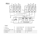
- FIG. 6 shows, in a greatly simplified diagram, one embodiment of the structure of the components that enable collaboration between the applications.
- FIG. 1 shows, greatly simplified and in schematic form, a system 1 for joint evaluation of medical image datasets B.
- the system 1 includes a plurality of data processing devices (e.g., devices 2 ) that are connected to one another for mutual data exchange via a network 3 (e.g., a data transmission network).
- a network 3 e.g., a data transmission network
- Each device 2 includes, for example, a processor 4 having connected visual display units 5 (e.g., one or more screens) and input units 6 for user interaction with the respective device 2 (e.g., a keyboard or a computer mouse).
- visual display units 5 e.g., one or more screens
- input units 6 for user interaction with the respective device 2 (e.g., a keyboard or a computer mouse).
- the four devices 2 include: an assessment station 7 , in which the processor 4 is formed, for example, by a powerful workstation, and which includes as visual display units 5 two large-format screens; a PC workstation 8 , in which the processor 4 is formed by a conventional desktop personal computer (PC) and the visual display units 5 are formed by a conventional computer monitor; a tablet 9 , in which the processor 4 , the visual display units 5 and the input units 6 are integrated in a portable compact unit with touch display; and a smartphone 10 , in which the processor 4 , the visual display units 5 , and the input units 6 are also integrated in a portable compact unit (e.g., of smaller format than the tablet 9 ) with touch display.
- an assessment station 7 in which the processor 4 is formed, for example, by a powerful workstation, and which includes as visual display units 5 two large-format screens
- a PC workstation 8 in which the processor 4 is formed by a conventional desktop personal computer (PC) and the visual display units 5 are formed by a conventional computer monitor
- the system 1 may also include data processing devices of other types, such as one or more notebooks.
- the system 1 may include any number of devices 2 , but at least two devices 2 .
- the devices 2 may be arranged spatially separated from one another in the operational condition of the system 1 . Any arrangement of devices 2 distributed worldwide may be provided.
- the assessment station 7 forms a constituent of an IT infrastructure of a medical facility (e.g., a clinic), while the PC workstation 8 is a home workstation in a private premises of the user, and the tablet 9 and the smartphone 10 are mobile units operated at varying locations.
- the network 3 includes, in one embodiment of the system 1 , a single, unified network or a plurality of cooperating subnetworks.
- the subnetworks of the network 3 include, for example, a wired LAN 11 of the medical facility in which the assessment station 7 is arranged, a wireless network 12 (e.g., a WLAN or a mobile telephone network) by which the tablet 9 and the smartphone 10 are linked to the system 1 , and the Internet 13 , by which the other subnetworks are connected to one another.
- Local subnetworks such as the LAN 11 are in this case typically connected to the Internet 13 by a firewall 14 , which is indicated by way of example.
- the system 1 includes a number of applications 15 (e.g., software applications) for displaying and processing the image datasets B.
- applications 15 e.g., software applications
- the same applications 15 may be implemented in all the devices 2 .
- different applications 15 or different variants of an application 15 that each have a range of functions adapted to a specific medical area of application and/or to the respectively associated device 2 are implemented on the individual devices 2 .
- the application 15 implemented in the assessment station 7 is formed by a full version of a specialized application for displaying and assessing mammogram images, while in the PC workstation 8 , for example, a version of the same application 15 that is limited in scope, from which numerically complex functions of the full version are omitted, is implemented.
- the applications 15 implemented are, for example, only generic display programs for image data (e.g., multi-modality readers) with no specialized functions for image processing and image evaluation.
- the system 1 includes, as regards software, a central collaboration unit 16 that coordinates cooperation between the individual applications 15 .
- the collaboration unit 16 is implemented in a cloud 17 (e.g., a public cloud; the “Azure” cloud service from Microsoft).
- the cloud 17 is, in this arrangement, not part of the system 1 in a strict sense but rather is only utilized by the system 1 .
- the system 1 includes a memory 18 in which the image datasets B are stored.
- the memory 18 is also arranged in the cloud 17 .
- the image datasets B may additionally or as an alternative also be stored at the location of one of the devices 2 (e.g., in the medical facility in which the assessment station 7 is arranged).
- the memory 18 may, for example, also include a plurality of individual memories that are arranged in one location or distributed across a plurality of locations.
- image datasets B of different types are stored in the memory 18 (e.g., single images (image datasets B having only two-dimensional image information, image stacks and volumes)). Purely for reasons of simplification, it will be assumed below that the image dataset B to be evaluated is a single image (e.g., a mammograph record).
- FIG. 2 shows, diagrammatically and greatly simplified, the structure of two applications 15 a and 15 b that may be any of the applications 15 shown in conjunction with FIG. 1 .
- each of the two applications 15 a , 15 b includes a graphical user interface (GUI) 20 .
- GUI graphical user interface
- each of the applications 15 a , 15 b includes one or more segments 21 , each of which serves to display a respective view V of the dataset B to be evaluated, and of which only one is illustrated in each case explicitly in FIG. 2 , purely for reasons of clarity.
- each segment 21 takes the form of a rectangular frame or window in which the view V is displayed.
- each segment 21 contains a number of drop-down menus that the user may activate by interaction with the GUI 20 (e.g., by clicking on a corresponding button with the mouse or a comparable input unit, or by performing a particular mouse pointer movement).
- the user may, by interaction with the GUI 20 , bring about actions for manipulating the displayed image data.
- the number of segments 20 positioned next to one another in the GUI 20 is in this case determined in user-specific manner.
- the user may open and close any desired number of segments 21 by interaction with the GUI 20 .
- each segment 21 may be formed by a front end 22 and a back end 23 , where the front end 22 defines the graphical operating elements of the segment 21 (e.g., the image plane and the drop-down menus), while the back end 23 contains the program logic that is linked to these operating elements.
- the functionality of the front end 22 and the back end 23 is grouped into a single software component.
- the applications 15 a , 15 b contain a respective associated pipeline 24 (e.g., image processing pipeline) that serves for deriving, from the underlying image dataset B, the view V that is to be presented in the respective segment 21 .
- a respective associated pipeline 24 e.g., image processing pipeline
- each pipeline 24 includes in each case a plurality of filters 25 that are connected one after the other and each of which performs a particular processing step on the data of the image dataset B in order to generate the view V from the original image dataset B.
- five filters 25 are illustrated, purely by way of example, and these are, for example, in the order of image processing: a filter 25 for selecting the image extract that is to be displayed of the original image data of the image dataset (including xy centering of the image center and zoom); a filter 25 for extracting the metadata to be displayed from the image dataset and distributing this metadata over the image plane; a filter 25 for selecting stored assessments F that are associated with the image extract and for positioning these assessments on the image plane; a filter 25 for adjusting the data of the image dataset, including the extracted assessments F, to the form factor of the respective device 2 ; and a filter 25 for combining the selected image data, metadata and assessments F to give the view V.
- the functions described in conjunction with the five filters 25 mentioned above may also be distributed over more than five filters 25 , or be grouped in a different form.
- the pipeline 25 may include numerous further filters.
- the image data of the image extract to be displayed is adapted to the screen resolution of the associated device 2 .
- the image information is scaled up or down appropriately in order to map the pixels of the image data extract onto a usually different number of screen pixels.
- a corresponding metadata image text (e.g., an item of image information containing alphanumeric information) is generated from the extracted metadata, where this image text is generated taking into account the form factor of the associated device 2 in order to provide legibility of the image text.
- the extracted assessments F that are distributed over the image plane are converted to a corresponding assessment image (e.g., an item of image information that reproduces the graphical and alphanumeric information).
- a corresponding assessment image e.g., an item of image information that reproduces the graphical and alphanumeric information.
- the form factor of the associated device 2 is taken into account in order to provide that the assessments are identifiable.
- the image text and the assessment image are overlaid on the actual image data.
- the finished view V thus contains the selected image extract of the image dataset, with a selection of metadata inset therein, and with the assessments F also inset.
- the view V is generated from the underlying image dataset B in a multi-stage process, in that image data, metadata, and assessments F pass through the filters 25 that are connected one after the other and in so doing are successively further processed.
- the individual filters 25 of the pipeline 24 (with the exception of the last filter 25 ) each pass partially processed data Ti to T 4 on to the respectively downstream filter 25 .
- the pipeline 24 is constructed such that individual filters 25 may be inserted into the pipeline 24 or removed from the pipeline 24 during the running time of the application 15 a , 15 b as a result of user interaction with the GUI 20 .
- a color filter (not explicitly illustrated) for coloring the image data, which is monochrome as standard, is inserted into the pipeline 24 if the user activates the color representation function in the segment 21 by selecting a corresponding menu item.
- Other filters 25 are inserted into the pipeline 24 or removed from the pipeline 24 automatically, as a function of the type of image dataset B loaded.
- Certain properties of at least some of the filters 25 are determined by parameters P that are pre-specified to the filters 25 by an event handler 26 .
- the event handler 26 determines the parameters P as a function of events E that are supplied and are either generated automatically by the application 15 a , 15 b or as a result of user interaction with the GUI 20 (e.g., actuation of the left-hand mouse button in a particular position of the mouse pointer).
- the parameters P determine, for example, the xy position of the original image data with respect to which the image extract to be displayed is to be centered, and a zoom factor, options for selecting the metadata, etc. to be displayed, options for presenting the assessments F, specifications of the script size of the metadata and assessments F to be inset, and specifications of whether the metadata image text and/or the assessment image is to be overlaid on the image data.
- the applications 15 a , 15 b also include a respective assessment management module 27 .
- the assessment management module 27 feeds the existing and newly created assessments F into the pipeline 24 .
- FIG. 2 shows the applications 15 a and 15 b described above in an operating mode in which the segments 21 of the applications 15 of the system 1 operate independently of one another in a manner conventional per se.
- this operating mode designated “standalone operation” below, there is no data exchange between the applications 15 a and 15 b and segments 21 thereof. For example, therefore, a joint evaluation of the image dataset B at a plurality of devices 2 is not supported in “standalone operation” by the applications 15 a , 15 b either.
- the applications 15 of the system 1 are set up such that individual segments 21 of the GUI 20 may be reversibly moved from “standalone operation” into a different operating mode, designated “collaborative operation” below and illustrated by FIGS. 4 and 5 .
- collaborative operation is characterized in that the pipelines 24 of two or more segments 21 of different applications 15 a , 15 b (which are usefully implemented on different devices 2 ) are coupled to one another, in that; according to the illustration from FIG. 4 , partially processed data T 3 is decoupled from the pipeline 24 of the segment 21 of a first application 15 (according to FIG. 4 , by way of example, application 15 a ) and coupled to the pipeline 24 of the segment 21 of at least one second application 15 (according to FIG. 4 , by way of example, application 15 b ).
- the pipeline 24 of the application 15 a and the associated segment 21 are thus operated as the presenter pipeline 30 and the presenter segment 31 .
- the pipeline 24 of the application 15 b and the associated segment 21 are by contrast operated as the observer pipeline 32 and the observer segment 33 .
- coupling of the pipelines 24 is achieved in that a respective coupling filter 34 and 35 are connected to the presenter pipeline 30 and the observer pipeline 32 , respectively.
- the coupling filter 34 decouples the data T 3 from the presenter pipeline 30 and transmits this data T 3 to the application 15 b .
- the coupling module 35 couples the data T 3 into the observer pipeline 32 at the same point in the processing sequence.
- the coupling filter 34 also outputs partially processed data T 3 ′ to the next filter 25 within the presenter pipeline 30 .
- the data T 3 ′ is, for example, substantially the same as the decoupled data T 3 .
- the data T 3 ′ differs from the data T 3 with respect to a mark 36 that is added by the coupling module 34 (e.g., in the form of a frame of a particular color (red)), which is displayed as part of the view V in the presenter segment 31 and thus visibly labels the presenter segment 31 as such ( FIG. 4 ).
- the coupling filter 35 replaces the data that is processed in the upstream filters 25 of the observer pipeline 32 with the data T 3 that is coupled in.
- the data T 3 from the presenter pipeline 30 thus takes over the observer pipeline 32 .
- the coupling filter 35 also adds an additional mark 37 to the data T 3 in the embodiment and passes correspondingly modified data T 3 ′ on to the downstream filter 25 .
- This mark 37 ( FIG. 4 ) may be generated in the form of a frame of a different color (e.g., yellow), which is displayed as part of the view V in the observer segment 33 and thus visibly labels the observer segment 33 as such.
- the coupling filters 34 and 35 are inserted into the presenter pipeline 30 and the observer pipeline 32 , respectively, such that all the medically relevant processing steps (e.g., selection of the image extract to be assessed, selection of the metadata to be displayed, selection of the assessments F to be displayed, where appropriate re-coloring of the image data, etc.) are performed only in the presenter pipeline 30 before the data T 3 is decoupled.
- form factor adjustment is performed after the data T 3 is decoupled and thus takes place in both the presenter pipeline 30 and the observer pipeline 32 , separately and independently of one another.
- Parameters P that are adjusted in each case to the form factor of the associated device 2 are predetermined for the filter 25 carrying out the form factor adjustment in the presenter pipeline 30 and in the observer pipeline 32 .
- image data with metadata and assessments F also takes place in both the presenter pipeline 30 and the observer pipeline 32 , separately and independently of one another.
- Image data, metadata, and assessments F are thus decoupled from the presenter pipeline 30 and coupled to the observer pipeline 32 as mutually separated constituent parts of the partially processed data T 3 , separately and independently of one another.
- the views V that are displayed in the presenter segment 31 and the observer segment 33 always contain the same medical image information, where this image information is in each case presented in a quality optimized for the respective device 2 .
- assessments F that are generated by the assessment management module 27 of the application 15 b based on inputs I by the user operating this application 15 b (“observer”) are not, as in standalone operation of the application 15 b , fed into the observer pipeline 32 . Rather, these assessments F that are generated at the observer end are transmitted to the application 15 a and managed by the assessment management module 27 there and are fed into the presenter pipeline 30 . As a result, the assessments F generated at the observer end are visible both in the presenter segment 31 and in the observer segment 33 .
- parameters P that are generated by the event handler 26 of the application 15 b based on events E occurring at the observer end are fed into the observer pipeline 32 .
- Another part of these parameters P is transmitted to the application 15 a and fed into the presenter pipeline 30 by the event handler 26 there.
- the parameters P that relate to the filters 25 upstream of the coupling filters 34 and 35 are transmitted to the application 15 a .
- parameters P that are generated at the observer end and relate to medically relevant image manipulation steps such as selection of the image extract, selection of the metadata, and selection of the assessments F are transmitted to the application 15 a and fed into the presenter pipeline 30 .
- transmission of the assessments F generated at the observer end and the parameters P generated at the observer end to the application 15 a is performed by withdrawable modules 38 , 39 , 40 and 41 that are coupled in collaborative operation (e.g., in the manner of plug-ins) to the assessment management module 27 at the observer end, the assessment management module 27 at the presenter end, the event handler 26 at the observer end, and the event handler 26 at the presenter end, respectively.
- withdrawable modules 38 , 39 , 40 and 41 are not provided. Instead, the function of these withdrawable modules 38 - 41 is implemented as a fixed (non-separable) constituent, which may be activated and deactivated during the running time of the applications 15 a , 15 b , of the assessment management modules 27 and event handlers 26 of the applications 15 a , 15 b.
- assessments F and parameters P generated at the observer end instead of assessments F and parameters P generated at the observer end, the underlying inputs I and events E of the second application 15 b are transmitted directly to the first application 15 a .
- assessments F and parameters P are derived from the transmitted inputs I and events E at the presenter end, by the application 15 a.
- Each segment 21 of the applications 15 a , 15 b may be switched reversibly between standalone operation, according to FIGS. 2, 3 , and collaborative operation, according to FIGS. 4, 5 , by the respective user by interaction with the GUI 20 .
- an operating element that is designated below as the collaboration pilot 42 ( FIG. 4 ) is displayed to the user by the respective application 15 a , 15 b , as a constituent of the GUI 20 (e.g., all the time or on activation by the user).
- this collaboration pilot 42 which is presented by way of example as a window or frame within the respective GUI 20 , the identities of the users who have declared their willingness to take part in a collaborative session at a common point in time by interaction with the GUI 20 are displayed.
- any collaborative session is characterized by coupling a presentation pipeline 30 to one or more observer pipelines 32 of other applications 15 and thus by an image dataset B that is to be evaluated jointly.
- one of the users concerned may be identified as the presenter in the collaboration pilot 42 by interaction with the GUI 20 .
- the further user or users who has/have declared their willingness to take part in the collaborative session are identified as observers in the collaboration pilot 42 .
- the user of the application 15 a who is identified, for example, as the presenter may, by interaction with the GUI 20 , mark the segment 21 there (or any of, where appropriate, a plurality of segments displayed in the GUI 20 ) as the presenter segment 31 by dragging an icon representing himself or herself in the GUI 20 into the desired segment 21 .
- the application 15 a switches the segment 21 concerned from standalone operation to collaborative operation, and activates the associated pipeline 24 as the presenter pipeline 30 by attaching the coupling filter 34 to the pipeline 24 , according to FIG. 5 , and coupling the withdrawable modules 39 and 41 to the assessment management module 27 and the event handler 26 , respectively.
- the user of the application 15 b who is identified, for example, as the observer, may, by interaction with the GUI 20 , mark the segment 21 there (or any of, where appropriate, a plurality of segments displayed in the GUI 20 ) as the observer segment 33 by dragging an icon representing himself or herself in the GUI 20 into the desired segment 21 .
- the application 15 b also switches the segment 21 concerned from standalone operation to collaborative operation, and activates the associated pipeline 24 as the observer pipeline 32 by attaching the coupling filter 35 to the pipeline 24 , according to FIG. 5 , and coupling the withdrawable modules 38 and 40 to the assessment management module 27 and the event handler 26 respectively.
- system 1 may, within the scope of one or more of the present embodiments, be constructed such that the applications 15 a , 15 b exchange data directly (e.g., peer to peer; the partially processed data T 3 and assessments F and parameters P that are generated at the observer end), in an embodiment of the system 1 , in collaborative operation, each of the applications 15 a , 15 b communicates in collaborative operation only with the central collaboration unit 16 that brings about data exchange between the applications 15 a , 15 b . In this arrangement, the central collaboration unit 16 also coordinates the collaboration pilot 42 of the applications 15 a , 15 b.
- data e.g., peer to peer; the partially processed data T 3 and assessments F and parameters P that are generated at the observer end
- each of the applications 15 a , 15 b communicates in collaborative operation only with the central collaboration unit 16 that brings about data exchange between the applications 15 a , 15 b .
- the central collaboration unit 16 also coordinates the collaboration pilot 42 of the applications 15 a , 15 b.
- each of the applications 15 is constructed for holding a plurality of collaborative sessions simultaneously.
- the applications 15 are set up such that, at the choice of the user, one or more segments 21 of the respective GUI 20 may be operated in collaborative operation simultaneously, but within the scope of different collaborative sessions.
- the applications 15 are constructed such that, for each application 15 , only a single segment 21 may be operated as the presenter segment 31 at one time.
- the sound and video transmission between the applications 15 a , 15 b is in this case also may be brought about by way of the central collaboration unit 16 .
- FIG. 6 the components of the system 1 that are involved in realizing the collaborative operation are once again illustrated, in an overview.
- FIG. 6 shows that a local collaboration unit 50 that combines the functions and components required for collaboration and communicates with the central collaboration unit 16 is associated with each application 15 .
- the local collaboration unit 50 that is associated with an application 15 thus includes, for example, the coupling filters 34 , 35 , the withdrawable modules 38 - 41 , and the collaboration pilot 42 .
- the local collaboration unit 50 may be constructed as separate modules that, for example in the manner of plug-ins, may be coupled to the respectively associated application 15 during running time.
- the local collaboration units 50 are implemented as a fixed constituent of the respectively associated application 15 a , 15 b.
- each local collaboration unit 50 contains a presenter channel 51 , by way of which individual segments 21 of the associated application 15 are accorded a respective role as presenter segment 31 or observer segment 33 .
- This presenter channel 51 which, for example, also controls the collaboration pilot 42 , communicates with a module of the central collaboration unit 16 that is designated the presentation manager 52 .
- the presentation manager 52 coordinates the roles of the segments 21 that are concerned, in the collaborative sessions that in each case involve more than one application.
- Each local collaboration unit 50 contains an event channel 53 , via which the events relevant to the collaboration are signaled between the applications 15 . These events include, for example, the provision of partially processed data T 3 through the presenter pipeline 30 , and the generation of new assessments F and parameters P at the observer end.
- This event channel 53 which cooperates, for example, with withdrawable modules 38 - 41 according to FIG. 5 , communicates with a corresponding module of the central collaboration unit 16 that is designated the event manager 54 .
- the event manager 54 manages and passes on the events that are fed to the event manager 54 in a manner involving more than one application.
- the exchange of the data T 3 , assessments F and parameters P that are connected with these events, is brought about via a module of the central collaboration unit 16 that is designated the data exchange manager 55 .
- the data exchange manager 55 handles the data for exchange independently of the respective data type, and in this sense, has no format.
- Each local collaboration unit 50 contains an audio channel 56 via which sound signals (and where appropriate video signals) that are captured in the course of the collaboration are exchanged.
- This audio channel 56 communicates with a corresponding module of the central collaboration unit 16 that is designated the audio manager 57 , where the audio manager 57 manages and passes on the sound signals (and where appropriate video signals) that are fed to the audio manager 57 .
Landscapes
- Engineering & Computer Science (AREA)
- Health & Medical Sciences (AREA)
- Medical Informatics (AREA)
- Biomedical Technology (AREA)
- Physics & Mathematics (AREA)
- Theoretical Computer Science (AREA)
- General Physics & Mathematics (AREA)
- General Health & Medical Sciences (AREA)
- Public Health (AREA)
- Epidemiology (AREA)
- Primary Health Care (AREA)
- General Business, Economics & Management (AREA)
- Business, Economics & Management (AREA)
- Pathology (AREA)
- Nuclear Medicine, Radiotherapy & Molecular Imaging (AREA)
- Radiology & Medical Imaging (AREA)
- Quality & Reliability (AREA)
- Computer Vision & Pattern Recognition (AREA)
- Processing Or Creating Images (AREA)
- Measuring And Recording Apparatus For Diagnosis (AREA)
- User Interface Of Digital Computer (AREA)
Abstract
Description
Claims (13)
Applications Claiming Priority (3)
| Application Number | Priority Date | Filing Date | Title |
|---|---|---|---|
| EP14198598.6A EP3035220B1 (en) | 2014-12-17 | 2014-12-17 | Method and system for joint evaluating a medicinal image database |
| EP14198598 | 2014-12-17 | ||
| EP14198598.6 | 2014-12-17 |
Publications (2)
| Publication Number | Publication Date |
|---|---|
| US20160180492A1 US20160180492A1 (en) | 2016-06-23 |
| US10163181B2 true US10163181B2 (en) | 2018-12-25 |
Family
ID=52394033
Family Applications (1)
| Application Number | Title | Priority Date | Filing Date |
|---|---|---|---|
| US14/973,202 Active 2036-12-16 US10163181B2 (en) | 2014-12-17 | 2015-12-17 | Method and system for joint evaluation of a medical image dataset |
Country Status (2)
| Country | Link |
|---|---|
| US (1) | US10163181B2 (en) |
| EP (1) | EP3035220B1 (en) |
Citations (6)
| Publication number | Priority date | Publication date | Assignee | Title |
|---|---|---|---|---|
| US5187790A (en) * | 1989-06-29 | 1993-02-16 | Digital Equipment Corporation | Server impersonation of client processes in an object based computer operating system |
| US20060235936A1 (en) | 2005-04-15 | 2006-10-19 | General Electric Company | System and method for PACS workstation conferencing |
| US20080085040A1 (en) * | 2006-10-05 | 2008-04-10 | General Electric Company | System and method for iterative reconstruction using mask images |
| US20110126127A1 (en) * | 2009-11-23 | 2011-05-26 | Foresight Imaging LLC | System and method for collaboratively communicating on images and saving those communications and images in a standard known format |
| US20120307116A1 (en) * | 2011-06-01 | 2012-12-06 | Lansel Steven P | Learning of Image Processing Pipeline for Digital Imaging Devices |
| US20140282624A1 (en) * | 2013-03-15 | 2014-09-18 | Varian Medical Systems, Inc. | Method and pipeline processing system for facilitating responsive interaction |
Family Cites Families (4)
| Publication number | Priority date | Publication date | Assignee | Title |
|---|---|---|---|---|
| US8819591B2 (en) * | 2009-10-30 | 2014-08-26 | Accuray Incorporated | Treatment planning in a virtual environment |
| US20110282686A1 (en) * | 2010-05-12 | 2011-11-17 | General Electric Company | Medical conferencing systems and methods |
| US8682049B2 (en) * | 2012-02-14 | 2014-03-25 | Terarecon, Inc. | Cloud-based medical image processing system with access control |
| US20140143298A1 (en) * | 2012-11-21 | 2014-05-22 | General Electric Company | Zero footprint dicom image viewer |
-
2014
- 2014-12-17 EP EP14198598.6A patent/EP3035220B1/en active Active
-
2015
- 2015-12-17 US US14/973,202 patent/US10163181B2/en active Active
Patent Citations (6)
| Publication number | Priority date | Publication date | Assignee | Title |
|---|---|---|---|---|
| US5187790A (en) * | 1989-06-29 | 1993-02-16 | Digital Equipment Corporation | Server impersonation of client processes in an object based computer operating system |
| US20060235936A1 (en) | 2005-04-15 | 2006-10-19 | General Electric Company | System and method for PACS workstation conferencing |
| US20080085040A1 (en) * | 2006-10-05 | 2008-04-10 | General Electric Company | System and method for iterative reconstruction using mask images |
| US20110126127A1 (en) * | 2009-11-23 | 2011-05-26 | Foresight Imaging LLC | System and method for collaboratively communicating on images and saving those communications and images in a standard known format |
| US20120307116A1 (en) * | 2011-06-01 | 2012-12-06 | Lansel Steven P | Learning of Image Processing Pipeline for Digital Imaging Devices |
| US20140282624A1 (en) * | 2013-03-15 | 2014-09-18 | Varian Medical Systems, Inc. | Method and pipeline processing system for facilitating responsive interaction |
Non-Patent Citations (1)
| Title |
|---|
| European Search Report for related European Application No. 14198598.6, dated May 29, 2015 with English Translation. |
Also Published As
| Publication number | Publication date |
|---|---|
| EP3035220A1 (en) | 2016-06-22 |
| EP3035220B1 (en) | 2024-09-18 |
| EP3035220C0 (en) | 2024-09-18 |
| US20160180492A1 (en) | 2016-06-23 |
Similar Documents
| Publication | Publication Date | Title |
|---|---|---|
| US11487412B2 (en) | Information processing method and information processing system | |
| AU2019101736A4 (en) | Medical virtual reality and mixed reality collaboration platform | |
| US10169534B2 (en) | Medical image display system and method | |
| US20160054897A1 (en) | Method and system for enabling interaction with a plurality of applications using a single user interface | |
| US9648057B2 (en) | Methods and systems for collaborative remote application sharing and conferencing | |
| US9741084B2 (en) | Method and system for providing remote access to data for display on a mobile device | |
| KR101474768B1 (en) | Medical device and image displaying method using the same | |
| US20200363924A1 (en) | Augmented reality drag and drop of objects | |
| US9372960B2 (en) | Medical support system and method thereof | |
| JP7059178B6 (en) | Data display device | |
| US10638089B2 (en) | System and method of collaboratively communication on images via input illustrations and have those illustrations auto erase | |
| JP5935216B2 (en) | Medical information display device and medical information display program | |
| CN110572591B (en) | KVM (keyboard, video and mouse) agent system signal source preview system and method | |
| NO331338B1 (en) | Method and apparatus for changing a video conferencing layout | |
| US9377925B2 (en) | GUI window with portal region for interacting with hidden interface elements | |
| US20150149195A1 (en) | Web-based interactive radiographic study session and interface | |
| CN112820385A (en) | Medical image browsing method, client and system | |
| CN109716278A (en) | Image procossing based on cloud is controlled by ensuring data confidentiality | |
| US10163181B2 (en) | Method and system for joint evaluation of a medical image dataset | |
| US7899884B2 (en) | Method and system for provision of image data from a server to a client | |
| KR101806816B1 (en) | Medical device and image displaying method using the same | |
| Gutenko et al. | Remote volume rendering pipeline for mHealth applications | |
| US7949705B1 (en) | Dynamic desktop switching for thin clients | |
| US20150145779A1 (en) | Image Display Apparatus And Image Display Method | |
| JP7517899B2 (en) | Display information control system and display information control method |
Legal Events
| Date | Code | Title | Description |
|---|---|---|---|
| AS | Assignment |
Owner name: SIEMENS AKTIENGESELLSCHAFT, GERMANY Free format text: ASSIGNMENT OF ASSIGNORS INTEREST;ASSIGNORS:DOMINICK, LUTZ;UKIS, VLADYSLAV;SIGNING DATES FROM 20160125 TO 20160128;REEL/FRAME:038110/0862 |
|
| STCF | Information on status: patent grant |
Free format text: PATENTED CASE |
|
| AS | Assignment |
Owner name: SIEMENS HEALTHCARE GMBH, GERMANY Free format text: ASSIGNMENT OF ASSIGNORS INTEREST;ASSIGNOR:SIEMENS AKTIENGESELLSCHAFT;REEL/FRAME:059764/0013 Effective date: 20220315 |
|
| MAFP | Maintenance fee payment |
Free format text: PAYMENT OF MAINTENANCE FEE, 4TH YEAR, LARGE ENTITY (ORIGINAL EVENT CODE: M1551); ENTITY STATUS OF PATENT OWNER: LARGE ENTITY Year of fee payment: 4 |
|
| AS | Assignment |
Owner name: SIEMENS HEALTHINEERS AG, GERMANY Free format text: ASSIGNMENT OF ASSIGNORS INTEREST;ASSIGNOR:SIEMENS HEALTHCARE GMBH;REEL/FRAME:066088/0256 Effective date: 20231219 |
|
| AS | Assignment |
Owner name: SIEMENS HEALTHINEERS AG, GERMANY Free format text: CORRECTIVE ASSIGNMENT TO CORRECT THE ASSIGNEE PREVIOUSLY RECORDED AT REEL: 066088 FRAME: 0256. ASSIGNOR(S) HEREBY CONFIRMS THE ASSIGNMENT;ASSIGNOR:SIEMENS HEALTHCARE GMBH;REEL/FRAME:071178/0246 Effective date: 20231219 |