US1016245A - Mathematical computer and register. - Google Patents
Mathematical computer and register. Download PDFInfo
- Publication number
- US1016245A US1016245A US64018411A US1911640184A US1016245A US 1016245 A US1016245 A US 1016245A US 64018411 A US64018411 A US 64018411A US 1911640184 A US1911640184 A US 1911640184A US 1016245 A US1016245 A US 1016245A
- Authority
- US
- United States
- Prior art keywords
- pointer
- bar
- sliding
- stationary
- register
- Prior art date
- Legal status (The legal status is an assumption and is not a legal conclusion. Google has not performed a legal analysis and makes no representation as to the accuracy of the status listed.)
- Expired - Lifetime
Links
Images

Classifications
-
- G—PHYSICS
- G06—COMPUTING OR CALCULATING; COUNTING
- G06G—ANALOGUE COMPUTERS
- G06G1/00—Hand-manipulated computing devices
- G06G1/02—Devices in which computing is effected by adding, subtracting, or comparing lengths of parallel or concentric graduated scales
- G06G1/04—Devices in which computing is effected by adding, subtracting, or comparing lengths of parallel or concentric graduated scales characterised by construction
Definitions
- the present invention relates to improvements in mathematical computers and registers, andthe primary object of the invention is the provision of a ycomputing or registering device especially applicable for use in keeping scale registers, or in fact for quickly computing in addition and subtrac tion, to obtain the gross and net weight in weighing loaded cars and wagons, or in fact for obtaining the sums in addition or the minuends in substraction for any pur-v pose whatsoever.
- a further object'of the invention is the provision of a rectangular receptacle provided with av series of longitudinally disposed and s aced divided or scaled bars, combined Wit a series of slidably ymounted bars or poises, each one of which is provided with a scale with proper registering markings thereon, combined with a slidably mounted auxiliary poise disposed upon the' main sliding poises and so mounted as to have its double arrow head or point reglster with the scale upon the stationary or main sliding bar to co-act with a pointer carried at the eXtreme left end of the slidable bar, to indicate the sum or minund particularly .pointed ⁇ to by the respective pointers.
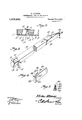
- FIG. 1 is a top plan view of the complete apparatus, the main poises being in various positions, to demonstrate the use of this invention.
- Fig. 2 is a perspective view of one of the main poises removed.
- Fig. 3 is a cross section taken on Specicationof Letters Patent. Application filed July 24 1911. Serial No. 640,184.
- Fig. i is a perspective view of one of the auxiliary poises. Fig.
- 5- is a cross section therethrough.
- the numeral 1 designates the metal receptacle provided with four upstanding portlons forming a rim to receive the transverse detachable end strip 2 which 'projects above the rims ot the receptacle and holds the respective Patented, Feb. 6,1912.
- the longivtudinally disposed strip 2 being/ mountedwithin the receptacle at the upper edge as clearly shown in Figs. 1 and 3.
- the stationary bars Disposed rigidly within the receptacle and parallel to each other, are the stationary bars, -3 4, 5, '6' and.7, whose opposed faces are inclined, sol as to provide dovetailed slots therebetween for the movable reception of the respective main sliding poises 3', 4', 5, 6 and, the same being inoperable relation to the respective stationary scale bars, and alll of said bars and poises being provided with scales as shown divided intov equal parts, to represent pounds, decimals of pounds, dollars and cents, tons and decimals of tons, or in fact any scale of weights and measures that may be desired.
- the main poises are so disposed within 'the spaces bet-Ween the stationary bars that the spaces 8 are provided, the
- Each one of the mam poises or bars, such as 3 as clearly shown in Fig. 2, are propurpose of vided at their left hand ends with the plates l Disposed upon the inner face of the mainv poise such as 3', and opposite the plate 9 is a plate 13, having the triangular shaped plate 14 formed at the inner end thereof and terminating in the angular flange or guiding arm 15, which is adapted to abut thebase 12 of its respective co-acting sta-- tionary bar 3 and thereby provide a means to retain the movable poise within the space between the stationary bars of the device.
- a plate 16 having the u standing finger engaging plate or flange 1% is mounted at the other end of the sliding poise, so that the said poise may be Vslid within the space between the main or stationary bars so that the pointer 11 may beistopped at the desired scale.
- auxiliary poises 22 Disposed to slide within the spaces -8 and be locked therein are the auxiliary poises 22, each of one of which consists of the block 23 dove-tail in cross section, and having mounted thereon the metal plate 24 havingthe upper short portion 25 resting upon the reduced upper edge of the block 23 and -provided with the upstanding nger engag- .ing fiange 26, and with the double pointed dove-tailed portion 27, having vthe upper tare rate pointer 28 and the lower gross rate pointer 29.
- the bar 3 and its sliding poise 3 will be illustrated as in. operation.
- the pointer 11 ind'cates 20 cent-s while the auxiliary poise indicator point indicates the gross 50 cents, while the tare rate pointer 28 indicates 30, so that the minuend would register 20 from 50- leaving 30, orfor addition 20 and 30 equals 50.
- all three of the indications are yindicated at once; and that b v the manipulation of the main sliding vpoise 3, so that its pointer 11 will indicate the amount it is desired to add to the tare rate carried by the poise 3', or, if desired, the gross rate carried. by the stationary bar 3.
- the pointer 11 In the position of the bar 5 and its sliding poise 5', the pointer 11 indicates 2,000, while the auxiliary poise indicates at the tare pointer 28 2,500 which if added to the 2,000 pointed by the pointer 11 shows as indicated by the gross pointer 29, the sum of 4,500. Or if desired to subtract, the 2,000 indicated by the pointer 11 subtracted from 'the/1,500 indicated by the pointer 29, will equal the tare as demonstrated by the tare pointer 28 of 2,500.
- the pointer 11 indicates 200, for instance dollars, while the tare pointer 28 indicates 800 dollars, the
- the subtraction that is 30 from 80 will indicate as shown Hby the pointer 28 the minuend of 50.
- a lmathematical computer and register having a receptacle, two stationary bars disposed longitudinally therewithin and providing a space dove-tailed in cross section, the lower lof said bars being provided upon its outer face with a graduated scale, a bar of lesser width than the dovetailed space and of a shorter length than the first twobars slidably mounted' within the space therebetween, guiding means carried at the respective ends thereof to retain said sliding bar within the space, a pointer carried by one end thereof projecting above the scale of the lower stationary bar, said sliding barv being provided with equal graduations to the lower bar. and a sliding poise disposed between the sliding bar and lower stationary bar, and provided with oppositely disposed pointers adapted to simultaneously indicate ther graduations upon the respective scales of the lower stationary bar and the sliding bar.
- a receptacle two stationary bars disposed longitudinally therewithin and providing a space dove-tailed in cross section, the lower of said bars being provided upon its outer face with a graduated scale, a bar of lesser width than the dove-tailed space and of a shorter length than the first two r bars slidably mounted within the space therebetween, a plate at each end of said sliding bar for engaging the lower stationary bar to retain the sliding bar Within vthe dove-tailed space, said sliding bar being narrower than said space and providing a dove-tailed in cross section space parallel with the sliding bar and between said plates,
- va pointer carried at one end of the sliding bar toproject above the scale of the lower the reduced dove-tailed space between stationary bar, said sliding bar being provided with similar graduations to the lower i hul', and a sliding poise dove-tailed in Cross section mounted for sliding movement in! sliding bar and lower stationary bar, said sliding poise having at one end oppositely disposed pointers to simultaneously indicate graduations upon the respective scales ofi the ture in the presence the lower bar.
Landscapes
- Physics & Mathematics (AREA)
- Engineering & Computer Science (AREA)
- Theoretical Computer Science (AREA)
- Mathematical Physics (AREA)
- Computer Hardware Design (AREA)
- General Physics & Mathematics (AREA)
- Orthopedics, Nursing, And Contraception (AREA)
Description
E. ATTAWY.
MATHBMATIGAL (BOMPUTBR AND REGISTER.
uPLIoATIloN FILED JULY 24, 1911.
1,016,245. l Patented Feb.6,1912.
SHEIITS-BHEET 1.
lllll *j/ff Z9 49 l lllllllll lllll l'llll E. ATTAWAY.
MATHEMATIGAL COMPUTER AND REGISTER.
APPLIGATION FILED JULY 111111 1.
1,016,245'. Tat-,amd Feb.v6,`1912.
ELISHiA ATTAWAY- ,'OF MORLBOW, LOUISIAYNA.
MAATHEMATICAL COMPUTER AND REGISTER.
To all 'whom tmay concern.'
- Be it known that I, ELISHA ATTAWAY, a citizen of the United States, 'residing at Morrow, in the parish of St. Landry and State of Louisiana, have invented a newv and useful' Mathematical Computer and Register,l of which the following is a speci-- ication.
The present invention relates to improvements in mathematical computers and registers, andthe primary object of the invention is the provision of a ycomputing or registering device especially applicable for use in keeping scale registers, or in fact for quickly computing in addition and subtrac tion, to obtain the gross and net weight in weighing loaded cars and wagons, or in fact for obtaining the sums in addition or the minuends in substraction for any pur-v pose whatsoever.-
A further object'of the invention is the provision of a rectangular receptacle provided with av series of longitudinally disposed and s aced divided or scaled bars, combined Wit a series of slidably ymounted bars or poises, each one of which is provided with a scale with proper registering markings thereon, combined with a slidably mounted auxiliary poise disposed upon the' main sliding poises and so mounted as to have its double arrow head or point reglster with the scale upon the stationary or main sliding bar to co-act with a pointer carried at the eXtreme left end of the slidable bar, to indicate the sum or minund particularly .pointed `to by the respective pointers. 1
With the foregoing and other objects in Iview which will appear as t-he description' proceeds, the invention resides in the arrangement and combination oi parts and in the details of construction hereinater described and claimed, it being understood that changes in the precise embodiment of invention herein disclosed can be made within the scope of what is claimed without departing from the spirit of the inven tion.
' In the drawings-Figure 1 is a top plan view of the complete apparatus, the main poises being in various positions, to demonstrate the use of this invention. Fig. 2 is a perspective view of one of the main poises removed. Fig. 3 is a cross section taken on Specicationof Letters Patent. Application filed July 24 1911. Serial No. 640,184.
line 3 3 (if Fig. 1. I Fig. i is a perspective view of one of the auxiliary poises. Fig.
5- is a cross section therethrough.
Referring to the drawings, the numeral 1 designates the metal receptacle provided with four upstanding portlons forming a rim to receive the transverse detachable end strip 2 which 'projects above the rims ot the receptacle and holds the respective Patented, Feb. 6,1912.
members within the receptacle, the longivtudinally disposed strip 2 being/ mountedwithin the receptacle at the upper edge as clearly shown in Figs. 1 and 3.
Disposed rigidly within the receptacle and parallel to each other, are the stationary bars, -3 4, 5, '6' and.7, whose opposed faces are inclined, sol as to provide dovetailed slots therebetween for the movable reception of the respective main sliding poises 3', 4', 5, 6 and, the same being inoperable relation to the respective stationary scale bars, and alll of said bars and poises being provided with scales as shown divided intov equal parts, to represent pounds, decimals of pounds, dollars and cents, tons and decimals of tons, or in fact any scale of weights and measures that may be desired.
The main poises are so disposed within 'the spaces bet-Ween the stationary bars that the spaces 8 are provided, the
which will presently appeai".
Each one of the mam poises or bars, such as 3 as clearly shown in Fig. 2, are propurpose of vided at their left hand ends with the plates l Disposed upon the inner face of the mainv poise such as 3', and opposite the plate 9 is a plate 13, having the triangular shaped plate 14 formed at the inner end thereof and terminating in the angular flange or guiding arm 15, which is adapted to abut thebase 12 of its respective co-acting sta-- tionary bar 3 and thereby provide a means to retain the movable poise within the space between the stationary bars of the device. Mounted atthe other end of the sliding poise is a plate 16 having the u standing finger engaging plate or flange 1%, so that the said poise may be Vslid within the space between the main or stationary bars so that the pointer 11 may beistopped at the desired scale.
In order to retain the body` and ends of 1, plate 21 which is a apted to engage the base 12 ofthe stationary bar similar to the flange 15, and thereby Ietain the sliding poises in relative parallel relation to the stationaryl batrs. Y
Disposed to slide within the spaces -8 and be locked therein are the auxiliary poises 22, each of one of which consists of the block 23 dove-tail in cross section, and having mounted thereon the metal plate 24 havingthe upper short portion 25 resting upon the reduced upper edge of the block 23 and -provided with the upstanding nger engag- .ing fiange 26, and with the double pointed dove-tailed portion 27, having vthe upper tare rate pointer 28 and the lower gross rate pointer 29.
4In order to properly demonstrate the use of the present:apparatus, the bar 3 and its sliding poise 3 will be illustrated as in. operation. For instance as shown in Fig. 1, the pointer 11 ind'cates 20 cent-s while the auxiliary poise indicator point indicates the gross 50 cents, while the tare rate pointer 28 indicates 30, so that the minuend would register 20 from 50- leaving 30, orfor addition 20 and 30 equals 50. It will thus be seen that all three of the indications are yindicated at once; and that b v the manipulation of the main sliding vpoise 3, so that its pointer 11 will indicate the amount it is desired to add to the tare rate carried by the poise 3', or, if desired, the gross rate carried. by the stationary bar 3.
The bar 4 and its sliding poise 4 is shown out of operation.
In the position of the bar 5 and its sliding poise 5', the pointer 11 indicates 2,000, while the auxiliary poise indicates at the tare pointer 28 2,500 which if added to the 2,000 pointed by the pointer 11 shows as indicated by the gross pointer 29, the sum of 4,500. Or if desired to subtract, the 2,000 indicated by the pointer 11 subtracted from 'the/1,500 indicated by the pointer 29, will equal the tare as demonstrated by the tare pointer 28 of 2,500.
As illustrated by the stationary bar 6 and its sliding poise 6, the pointer 11 indicates 200, for instance dollars, while the tare pointer 28 indicates 800 dollars, the
that the 200 indicated by the pointer 11 added to the 800 pointed'by the tare pointery 28 will .equal the amount pointed to by the pointer 29 or 1,000-dollars. To subtract indicatethe minuend200, while to subtract the 200 from the 1,000 the pointer 28 will indicate the minuend/.of 800.
As indicated by the stationary bar l7 and its movable poise 7', the pointerltindicates .30 while the pointer 28 of thel auxiliary poise indicates 50, which if added to the 30 will indicate as pointed by the pointer 29, the sum of 80. The subtraction that is 30 from 80 will indicate as shown Hby the pointer 28 the minuend of 50.
From this description it will be noted that the manipulation of this device is very simple and that a person of ordinary intelligence can keepa register or record of `the weights, and should'it be desired to continue an account or register, it is simplynecessary to manipulate the movable poises with relation to the stationary bars and the auxil iary poises, adding and subtracting as desired any'of three numbers, giving at an instant, the sum or the minuend, as clearly set forth in the' examples heretofore given.
What is claimed is: l. In a lmathematical computer and register, having a receptacle, two stationary bars disposed longitudinally therewithin and providing a space dove-tailed in cross section, the lower lof said bars being provided upon its outer face with a graduated scale, a bar of lesser width than the dovetailed space and of a shorter length than the first twobars slidably mounted' within the space therebetween, guiding means carried at the respective ends thereof to retain said sliding bar within the space, a pointer carried by one end thereof projecting above the scale of the lower stationary bar, said sliding barv being provided with equal graduations to the lower bar. and a sliding poise disposed between the sliding bar and lower stationary bar, and provided with oppositely disposed pointers adapted to simultaneously indicate ther graduations upon the respective scales of the lower stationary bar and the sliding bar.
2. In a mathematical computer and register, a receptacle, two stationary bars disposed longitudinally therewithin and providing a space dove-tailed in cross section, the lower of said bars being provided upon its outer face with a graduated scale, a bar of lesser width than the dove-tailed space and of a shorter length than the first two r bars slidably mounted within the space therebetween, a plate at each end of said sliding bar for engaging the lower stationary bar to retain the sliding bar Within vthe dove-tailed space, said sliding bar being narrower than said space and providing a dove-tailed in cross section space parallel with the sliding bar and between said plates,
va pointer carried at one end of the sliding bar toproject above the scale of the lower the reduced dove-tailed space between stationary bar, said sliding bar being provided with similar graduations to the lower i hul', and a sliding poise dove-tailed in Cross section mounted for sliding movement in! sliding bar and lower stationary bar, said sliding poise having at one end oppositely disposed pointers to simultaneously indicate graduations upon the respective scales ofi the ture in the presence the lower bar.
In testimony that I claim the foregoing as my own, 1 have hereto axed my signaof two witnesses.
ELSHA ATTAWAY.
Stationary bul' und the sliding 10 Witnesses:
W. W. HALEY, S. L. GIPsoN.
Priority Applications (1)
| Application Number | Priority Date | Filing Date | Title |
|---|---|---|---|
| US64018411A US1016245A (en) | 1911-07-24 | 1911-07-24 | Mathematical computer and register. |
Applications Claiming Priority (1)
| Application Number | Priority Date | Filing Date | Title |
|---|---|---|---|
| US64018411A US1016245A (en) | 1911-07-24 | 1911-07-24 | Mathematical computer and register. |
Publications (1)
| Publication Number | Publication Date |
|---|---|
| US1016245A true US1016245A (en) | 1912-02-06 |
Family
ID=3084548
Family Applications (1)
| Application Number | Title | Priority Date | Filing Date |
|---|---|---|---|
| US64018411A Expired - Lifetime US1016245A (en) | 1911-07-24 | 1911-07-24 | Mathematical computer and register. |
Country Status (1)
| Country | Link |
|---|---|
| US (1) | US1016245A (en) |
-
1911
- 1911-07-24 US US64018411A patent/US1016245A/en not_active Expired - Lifetime
Similar Documents
| Publication | Publication Date | Title |
|---|---|---|
| US1016245A (en) | Mathematical computer and register. | |
| US442020A (en) | Island | |
| US1040592A (en) | Computing device. | |
| US576900A (en) | Measuring instrument | |
| US732935A (en) | Slide-rule. | |
| US515978A (en) | Calculating-rule | |
| US517698A (en) | Druggist s weighing-scale | |
| US1560747A (en) | Vector calculator | |
| US397686A (en) | Scale for surface measurements | |
| US903711A (en) | Chart for scales. | |
| US1230232A (en) | Weighing-balance. | |
| US1648497A (en) | Micrometer | |
| US847904A (en) | Spring-load computer. | |
| US600837A (en) | Island | |
| US597670A (en) | Price-scale | |
| US576468A (en) | Computing-scale | |
| US674802A (en) | Ticket-holder and indicator-plate. | |
| US1816548A (en) | Simplified rule | |
| US1180277A (en) | Computing scale-beam. | |
| US852552A (en) | Computing-scale. | |
| US352408A (en) | Calculator | |
| US2424713A (en) | Vernier for slide rules | |
| US493636A (en) | Edward s | |
| US8748A (en) | Improvement in weighing-machines | |
| US1808981A (en) | Calculating device |