US10161563B1 - Stand clamp with ease of force application - Google Patents
Stand clamp with ease of force application Download PDFInfo
- Publication number
- US10161563B1 US10161563B1 US15/692,472 US201715692472A US10161563B1 US 10161563 B1 US10161563 B1 US 10161563B1 US 201715692472 A US201715692472 A US 201715692472A US 10161563 B1 US10161563 B1 US 10161563B1
- Authority
- US
- United States
- Prior art keywords
- rotating rod
- bolt
- stand
- movable part
- ease
- Prior art date
- Legal status (The legal status is an assumption and is not a legal conclusion. Google has not performed a legal analysis and makes no representation as to the accuracy of the status listed.)
- Active
Links
- 230000006835 compression Effects 0.000 claims description 5
- 238000007906 compression Methods 0.000 claims description 5
- 238000010586 diagram Methods 0.000 description 8
- 235000011312 Silene vulgaris Nutrition 0.000 description 4
- 240000000022 Silene vulgaris Species 0.000 description 4
- 238000013459 approach Methods 0.000 description 1
Images


Classifications
-
- F—MECHANICAL ENGINEERING; LIGHTING; HEATING; WEAPONS; BLASTING
- F16—ENGINEERING ELEMENTS AND UNITS; GENERAL MEASURES FOR PRODUCING AND MAINTAINING EFFECTIVE FUNCTIONING OF MACHINES OR INSTALLATIONS; THERMAL INSULATION IN GENERAL
- F16M—FRAMES, CASINGS OR BEDS OF ENGINES, MACHINES OR APPARATUS, NOT SPECIFIC TO ENGINES, MACHINES OR APPARATUS PROVIDED FOR ELSEWHERE; STANDS; SUPPORTS
- F16M13/00—Other supports for positioning apparatus or articles; Means for steadying hand-held apparatus or articles
- F16M13/02—Other supports for positioning apparatus or articles; Means for steadying hand-held apparatus or articles for supporting on, or attaching to, an object, e.g. tree, gate, window-frame, cycle
- F16M13/022—Other supports for positioning apparatus or articles; Means for steadying hand-held apparatus or articles for supporting on, or attaching to, an object, e.g. tree, gate, window-frame, cycle repositionable
-
- F—MECHANICAL ENGINEERING; LIGHTING; HEATING; WEAPONS; BLASTING
- F16—ENGINEERING ELEMENTS AND UNITS; GENERAL MEASURES FOR PRODUCING AND MAINTAINING EFFECTIVE FUNCTIONING OF MACHINES OR INSTALLATIONS; THERMAL INSULATION IN GENERAL
- F16B—DEVICES FOR FASTENING OR SECURING CONSTRUCTIONAL ELEMENTS OR MACHINE PARTS TOGETHER, e.g. NAILS, BOLTS, CIRCLIPS, CLAMPS, CLIPS OR WEDGES; JOINTS OR JOINTING
- F16B2/00—Friction-grip releasable fastenings
- F16B2/02—Clamps, i.e. with gripping action effected by positive means other than the inherent resistance to deformation of the material of the fastening
- F16B2/06—Clamps, i.e. with gripping action effected by positive means other than the inherent resistance to deformation of the material of the fastening external, i.e. with contracting action
- F16B2/10—Clamps, i.e. with gripping action effected by positive means other than the inherent resistance to deformation of the material of the fastening external, i.e. with contracting action using pivoting jaws
-
- F—MECHANICAL ENGINEERING; LIGHTING; HEATING; WEAPONS; BLASTING
- F16—ENGINEERING ELEMENTS AND UNITS; GENERAL MEASURES FOR PRODUCING AND MAINTAINING EFFECTIVE FUNCTIONING OF MACHINES OR INSTALLATIONS; THERMAL INSULATION IN GENERAL
- F16M—FRAMES, CASINGS OR BEDS OF ENGINES, MACHINES OR APPARATUS, NOT SPECIFIC TO ENGINES, MACHINES OR APPARATUS PROVIDED FOR ELSEWHERE; STANDS; SUPPORTS
- F16M11/00—Stands or trestles as supports for apparatus or articles placed thereon ; Stands for scientific apparatus such as gravitational force meters
- F16M11/02—Heads
- F16M11/04—Means for attachment of apparatus; Means allowing adjustment of the apparatus relatively to the stand
- F16M11/043—Allowing translations
- F16M11/046—Allowing translations adapted to upward-downward translation movement
-
- F—MECHANICAL ENGINEERING; LIGHTING; HEATING; WEAPONS; BLASTING
- F16—ENGINEERING ELEMENTS AND UNITS; GENERAL MEASURES FOR PRODUCING AND MAINTAINING EFFECTIVE FUNCTIONING OF MACHINES OR INSTALLATIONS; THERMAL INSULATION IN GENERAL
- F16M—FRAMES, CASINGS OR BEDS OF ENGINES, MACHINES OR APPARATUS, NOT SPECIFIC TO ENGINES, MACHINES OR APPARATUS PROVIDED FOR ELSEWHERE; STANDS; SUPPORTS
- F16M11/00—Stands or trestles as supports for apparatus or articles placed thereon ; Stands for scientific apparatus such as gravitational force meters
- F16M11/20—Undercarriages with or without wheels
- F16M11/2007—Undercarriages with or without wheels comprising means allowing pivoting adjustment
- F16M11/2021—Undercarriages with or without wheels comprising means allowing pivoting adjustment around a horizontal axis
-
- G—PHYSICS
- G10—MUSICAL INSTRUMENTS; ACOUSTICS
- G10D—STRINGED MUSICAL INSTRUMENTS; WIND MUSICAL INSTRUMENTS; ACCORDIONS OR CONCERTINAS; PERCUSSION MUSICAL INSTRUMENTS; AEOLIAN HARPS; SINGING-FLAME MUSICAL INSTRUMENTS; MUSICAL INSTRUMENTS NOT OTHERWISE PROVIDED FOR
- G10D13/00—Percussion musical instruments; Details or accessories therefor
- G10D13/01—General design of percussion musical instruments
- G10D13/02—Drums; Tambourines with drumheads
-
- G10D13/026—
-
- G—PHYSICS
- G10—MUSICAL INSTRUMENTS; ACOUSTICS
- G10D—STRINGED MUSICAL INSTRUMENTS; WIND MUSICAL INSTRUMENTS; ACCORDIONS OR CONCERTINAS; PERCUSSION MUSICAL INSTRUMENTS; AEOLIAN HARPS; SINGING-FLAME MUSICAL INSTRUMENTS; MUSICAL INSTRUMENTS NOT OTHERWISE PROVIDED FOR
- G10D13/00—Percussion musical instruments; Details or accessories therefor
- G10D13/10—Details of, or accessories for, percussion musical instruments
- G10D13/28—Mountings or supports for individual drums
-
- G—PHYSICS
- G10—MUSICAL INSTRUMENTS; ACOUSTICS
- G10G—REPRESENTATION OF MUSIC; RECORDING MUSIC IN NOTATION FORM; ACCESSORIES FOR MUSIC OR MUSICAL INSTRUMENTS NOT OTHERWISE PROVIDED FOR, e.g. SUPPORTS
- G10G5/00—Supports for musical instruments
-
- G—PHYSICS
- G10—MUSICAL INSTRUMENTS; ACOUSTICS
- G10G—REPRESENTATION OF MUSIC; RECORDING MUSIC IN NOTATION FORM; ACCESSORIES FOR MUSIC OR MUSICAL INSTRUMENTS NOT OTHERWISE PROVIDED FOR, e.g. SUPPORTS
- G10G5/00—Supports for musical instruments
- G10G5/005—Supports for musical instruments while playing, e.g. cord, strap or harness
-
- A—HUMAN NECESSITIES
- A01—AGRICULTURE; FORESTRY; ANIMAL HUSBANDRY; HUNTING; TRAPPING; FISHING
- A01C—PLANTING; SOWING; FERTILISING
- A01C5/00—Making or covering furrows or holes for sowing, planting or manuring
- A01C5/06—Machines for making or covering drills or furrows for sowing or planting
- A01C5/066—Devices for covering drills or furrows
- A01C5/068—Furrow packing devices, e.g. press wheels
-
- F—MECHANICAL ENGINEERING; LIGHTING; HEATING; WEAPONS; BLASTING
- F16—ENGINEERING ELEMENTS AND UNITS; GENERAL MEASURES FOR PRODUCING AND MAINTAINING EFFECTIVE FUNCTIONING OF MACHINES OR INSTALLATIONS; THERMAL INSULATION IN GENERAL
- F16B—DEVICES FOR FASTENING OR SECURING CONSTRUCTIONAL ELEMENTS OR MACHINE PARTS TOGETHER, e.g. NAILS, BOLTS, CIRCLIPS, CLAMPS, CLIPS OR WEDGES; JOINTS OR JOINTING
- F16B2/00—Friction-grip releasable fastenings
- F16B2/02—Clamps, i.e. with gripping action effected by positive means other than the inherent resistance to deformation of the material of the fastening
- F16B2/06—Clamps, i.e. with gripping action effected by positive means other than the inherent resistance to deformation of the material of the fastening external, i.e. with contracting action
- F16B2/065—Clamps, i.e. with gripping action effected by positive means other than the inherent resistance to deformation of the material of the fastening external, i.e. with contracting action using screw-thread elements
-
- F—MECHANICAL ENGINEERING; LIGHTING; HEATING; WEAPONS; BLASTING
- F16—ENGINEERING ELEMENTS AND UNITS; GENERAL MEASURES FOR PRODUCING AND MAINTAINING EFFECTIVE FUNCTIONING OF MACHINES OR INSTALLATIONS; THERMAL INSULATION IN GENERAL
- F16M—FRAMES, CASINGS OR BEDS OF ENGINES, MACHINES OR APPARATUS, NOT SPECIFIC TO ENGINES, MACHINES OR APPARATUS PROVIDED FOR ELSEWHERE; STANDS; SUPPORTS
- F16M2200/00—Details of stands or supports
- F16M2200/02—Locking means
- F16M2200/021—Locking means for rotational movement
- F16M2200/022—Locking means for rotational movement by friction
-
- F—MECHANICAL ENGINEERING; LIGHTING; HEATING; WEAPONS; BLASTING
- F16—ENGINEERING ELEMENTS AND UNITS; GENERAL MEASURES FOR PRODUCING AND MAINTAINING EFFECTIVE FUNCTIONING OF MACHINES OR INSTALLATIONS; THERMAL INSULATION IN GENERAL
- F16M—FRAMES, CASINGS OR BEDS OF ENGINES, MACHINES OR APPARATUS, NOT SPECIFIC TO ENGINES, MACHINES OR APPARATUS PROVIDED FOR ELSEWHERE; STANDS; SUPPORTS
- F16M2200/00—Details of stands or supports
- F16M2200/02—Locking means
- F16M2200/025—Locking means for translational movement
- F16M2200/027—Locking means for translational movement by friction
Definitions
- the present invention relates to a stand clamp, and more particularly relates to a locking structure of the stand clamp.
- a musical instrument such as a pair of cymbals, a drum or a cow-bell, may be fixed to a stand (not shown), whereby they can be arranged around the performer.
- the conventional stand clamp comprises a fixed part 1 , a movable part 2 and a screwing-lock part 3 , wherein the movable part 2 is pivotally coupled to a pivotal point 4 of the fixed part 1 , and the movable part 2 is provided with an outer curved surface 5 at one side far away from the fixed part 1 .
- the screwing-lock part 3 is configured to screwing-lock the outer curved surface 5 which passes through the fixed part 1 and presses the movable part 2 , such that the movable part 2 rotates with respect to the fixed part 1 and the movable part 2 approaches to the fixed part 1 , whereby the movable part 2 is clamped to the stand.
- the conventional stand clamp can be clamped to the stand by rotating the screwing-lock part 3 . Since the conventional screwing-lock part 3 is generally of a knob structure, it is quite difficult to clamp for those people who have less effort. If the screwing-lock part 3 is lengthened, the torque can be increased and the screwing-lock part can be easily clamped by an operator, but the lengthened screwing-lock part 3 will occupy a space and may not be stored easily. Once the screwing-lock part 3 is not clamped, it is possible to slip to cause drop of a musical instrument, such as a pair of cymbals, a drum or a cow-bell lest the performance be affected or the musical instrument be damaged, and it is obvious that the requirement on use cannot be satisfied.
- a musical instrument such as a pair of cymbals, a drum or a cow-bell
- the primary objective of the present invention is to disclose a stand clamp with ease of force application, in which a rotating rod can freely rotate to a most suitable application angle and is then tightened.
- the present invention proposes a stand clamp with ease of force application, which is to be locked and fixed to a stand and comprises a fixed part, a movable part and a screwing-lock part, wherein the movable part is pivotally coupled to the fixed part.
- the movable part rotates with respect to the fixed part to form a clamping area.
- the movable part is provided with an outer curved surface at one side far away from the fixed part.
- the screwing-lock part includes a bolt, a pressing plate, a rotating rod and a resetting assembly, wherein two ends of the bolt are provided with a threaded section and a ratchet wheel section respectively.
- the bolt presses the outer curved surface of the movable part across the pressing plate, and the threaded section passes through the pressing plate and is locked to the fixed part, such that the pressing plate presses the movable part to rotate to reduce the clamping area and to be locked and fixed to the stand.
- the rotating rod slips with respect to the bolt to form a reset position and an actuating position.
- the resetting assembly is linked to the bolt and the rotating rod, such that the rotating rod is in the reset position under an ordinary state, and the rotating rod is provided with a ratchet which is engaged with the ratchet wheel section correspondingly at the reset position.
- the rotating rod can freely rotate with respect to the bolt at the actuating position.
- the rotating rod can freely rotate with respect to the bolt at the actuating position, i.e., an operator can allow the rotating rod to be in the actuating position first and freely rotate the rotating rod, such that a most suitable application angle can be selected; while when the rotating rod is locked and fixed to the stand, it can return to the reset position by using the resetting assembly, such that the ratchet is engaged with the ratchet wheel section, and therefore the rotating rod rotates to drive the bolt to rotate, and further, the pressing plate is enabled to press the movable part to rotate to reduce the clamping area and to be locked and fixed to the stand.
- FIG. 1 is a schematic diagram showing the usage of a conventional stand clamp with ease of force application
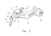
- FIG. 2 is a combined structure diagram of the present invention
- FIG. 3 is a locally exploded structure diagram of the present invention.
- FIG. 4A is a sectional schematic diagram when the rotating rod is located in a reset position according to the present invention.
- FIG. 4B is a sectional schematic diagram when the rotating rod is located in an actuating position according to the present invention.
- FIG. 5 is an implementation schematic diagram of the present invention.
- FIG. 6 is another implementation schematic diagram of the present invention.
- FIG. 7 is yet another implementation schematic diagram of the present invention.
- the present invention proposes a stand clamp with ease of force application, which is to be locked and fixed to a stand 10 and comprises a fixed part 20 , a movable part 30 and a screwing-lock part 40 , wherein the movable part 30 is pivotally coupled to the fixed part 20 .
- the movable part 30 rotates with respect to the fixed part 20 to form a clamping area 50 .
- the movable part 30 is provided with an outer curved surface 31 at one side far away from the fixed part 20 .
- the screwing-lock part 40 is provided with a bolt 41 , a pressing plate 42 , a rotating rod 43 and a resetting assembly 44 , wherein two ends of the bolt 41 are provided with a threaded section 411 and a ratchet wheel section 412 respectively.
- the bolt 41 presses the outer curved surface 31 of the movable part 30 across the pressing plate 42 , and the threaded section 411 passes through the pressing plate 42 and is locked to the fixed part 20 , such that the pressing plate 42 presses the movable part 30 to rotate to reduce the clamping area 50 and to be locked and fixed to the stand 10 .
- the rotating rod 43 slips with respect to the bolt 41 to form a reset position (as shown in FIG. 4A ) and an actuating position (as shown in FIG. 4B ).
- the resetting assembly 44 is linked to the bolt 41 and the rotating rod 43 , such that the rotating rod 43 is in the reset position under an ordinary state, and the rotating rod 43 is provided with a ratchet 432 which is engaged with the ratchet wheel section 412 correspondingly at the reset position.
- the rotating rod 43 can freely rotate with respect to the bolt 41 at the actuating position.
- the resetting assembly 44 may be provided with a compression spring 45 and a nut 46 .
- the nut 46 is provided with a head part 461 and a screwing-lock stud 462 , wherein the screwing-lock stud 462 passes through the rotating rod 43 and is locked to the bolt 41 , and a variable gap 47 is formed between the head part 461 and the rotating rod 43 .
- the compression spring 45 is provided inside the variable gap 47 in a compressed manner.
- the rotating rod 43 is kept in the reset position under an ordinary state, and the rotating rod 43 slips with respect to the bolt 41 to compress the variable gap 47 , till the ratchet 432 is separated from the ratchet wheel section 412 and is in the actuating position.
- the rotating rod 43 may be provided with a recessed space 431 for accommodating the head part 461 .
- the recessed space 431 can prevent the head part 461 from exposing and hide the compression spring 45 .
- the rotating rod 43 may be provided with an inner ring surface 433 through which the ratchet wheel section 412 passes and on which the ratchet 432 is formed.
- each of the movable part 30 and the fixed part 20 is provided with a cushion 32 contacting the stand 10 , and when they are clamped to the stand 10 , the stability can be increased.
- the movable part 30 may be provided with an accommodating groove 33 in which the fixed part 20 can be embedded.
- the fixed part 20 is configured to fix various musical instruments, and may be, in implementation, provided with a connector 60 .
- the connector 60 may allow a pair of cymbals 70 to be arranged thereon to fix the cymbals 70 , or as shown in FIG. 6 , may allow a cow-bell 80 to be arranged thereon to fix the cow-bell 80 .
- a spherical universal head 21 may be provided on the fixed part 20 . The spherical universal head 21 is connected to an L-shaped rod 22 which is then connected to the connector 60 for assembly of a musical instrument support 90 .
- the movable part 30 and the fixed part 20 are locked to the stand 10 .
- the operator can allow the rotating rod 43 to be in an actuating position first and then freely rotate the rotating rod 43 (as shown in FIG. 4B ).
- the operator may select a most suitable force application angle, and after the rotating rod 43 is adjusted to the most suitable force application angle, the rotating rod 43 can return to the reset position (as shown in FIG. 4A ) using a resetting force of the resetting assembly 44 .
- the ratchet 432 is engaged with the ratchet wheel section 412 , i.e., the rotating rod 43 rotates to drive the bolt 41 to rotate, whereby the pressing plate 42 can be pressed to press the movable part 30 to rotate, and the clamping area 50 will be reduced and be locked and fixed to the stand 10 .
- the present invention at least includes the following advantages:
- the rotating rod can freely rotate with respect to the bolt at the actuating position, and therefore, the most suitable force application angle can be selected tolock, and the musical instrument can be fixed firmly.
- the rotating rod is allowed to be in a reset position under an ordinary state, and thereby the rotating rod is prevented from shaking.
- the rotating rod After the rotating rod is unused (locked), the rotating rod can freely rotate with respect to the bolt to a suitable storage position, and therefore, the case where the performance is affected can be avoided; in addition, the rotating rod can be lengthened appropriately to increase a torque and reduce an effort required for locking.
Landscapes
- Engineering & Computer Science (AREA)
- General Engineering & Computer Science (AREA)
- Mechanical Engineering (AREA)
- Physics & Mathematics (AREA)
- Acoustics & Sound (AREA)
- Multimedia (AREA)
- Auxiliary Devices For Music (AREA)
Abstract
The stand clamp with ease of force application comprises a fixed part, a movable part and a screwing-lock part. The movable part is pivotally coupled to the fixed part. The screwing-lock part includes a bolt, a pressing plate, a rotating rod and a resetting assembly, wherein two ends of the bolt are provided with a threaded section and a ratchet wheel section respectively. Further, the rotating rod slips with respect to the bolt to form a reset position and an actuating position. The resetting assembly is linked to the bolt and the rotating rod, such that the rotating rod is in the reset position under an ordinary state. In addition, the rotating rod can freely rotate with respect to the bolt at the actuating position. Therefore, an operator can freely change the position of the rotating rod and apply a force with a most suitable application angle.
Description
The present invention relates to a stand clamp, and more particularly relates to a locking structure of the stand clamp.
Refer to FIG. 1 , according to a publication of U.S. Pat. No. 9,633,635 B2, a musical instrument, such as a pair of cymbals, a drum or a cow-bell, may be fixed to a stand (not shown), whereby they can be arranged around the performer.
The conventional stand clamp comprises a fixed part 1, a movable part 2 and a screwing-lock part 3, wherein the movable part 2 is pivotally coupled to a pivotal point 4 of the fixed part 1, and the movable part 2 is provided with an outer curved surface 5 at one side far away from the fixed part 1. The screwing-lock part 3 is configured to screwing-lock the outer curved surface 5 which passes through the fixed part 1 and presses the movable part 2, such that the movable part 2 rotates with respect to the fixed part 1 and the movable part 2 approaches to the fixed part 1, whereby the movable part 2 is clamped to the stand.
The conventional stand clamp can be clamped to the stand by rotating the screwing-lock part 3. Since the conventional screwing-lock part 3 is generally of a knob structure, it is quite difficult to clamp for those people who have less effort. If the screwing-lock part 3 is lengthened, the torque can be increased and the screwing-lock part can be easily clamped by an operator, but the lengthened screwing-lock part 3 will occupy a space and may not be stored easily. Once the screwing-lock part 3 is not clamped, it is possible to slip to cause drop of a musical instrument, such as a pair of cymbals, a drum or a cow-bell lest the performance be affected or the musical instrument be damaged, and it is obvious that the requirement on use cannot be satisfied.
Therefore, the primary objective of the present invention is to disclose a stand clamp with ease of force application, in which a rotating rod can freely rotate to a most suitable application angle and is then tightened.
To achieve the above-mentioned objective, the present invention proposes a stand clamp with ease of force application, which is to be locked and fixed to a stand and comprises a fixed part, a movable part and a screwing-lock part, wherein the movable part is pivotally coupled to the fixed part. The movable part rotates with respect to the fixed part to form a clamping area. The movable part is provided with an outer curved surface at one side far away from the fixed part. The screwing-lock part includes a bolt, a pressing plate, a rotating rod and a resetting assembly, wherein two ends of the bolt are provided with a threaded section and a ratchet wheel section respectively. The bolt presses the outer curved surface of the movable part across the pressing plate, and the threaded section passes through the pressing plate and is locked to the fixed part, such that the pressing plate presses the movable part to rotate to reduce the clamping area and to be locked and fixed to the stand. Further, the rotating rod slips with respect to the bolt to form a reset position and an actuating position. The resetting assembly is linked to the bolt and the rotating rod, such that the rotating rod is in the reset position under an ordinary state, and the rotating rod is provided with a ratchet which is engaged with the ratchet wheel section correspondingly at the reset position. In addition, the rotating rod can freely rotate with respect to the bolt at the actuating position.
Therefore, since the rotating rod can freely rotate with respect to the bolt at the actuating position, i.e., an operator can allow the rotating rod to be in the actuating position first and freely rotate the rotating rod, such that a most suitable application angle can be selected; while when the rotating rod is locked and fixed to the stand, it can return to the reset position by using the resetting assembly, such that the ratchet is engaged with the ratchet wheel section, and therefore the rotating rod rotates to drive the bolt to rotate, and further, the pressing plate is enabled to press the movable part to rotate to reduce the clamping area and to be locked and fixed to the stand.
The preferred embodiments will be described in detail in cooperation with the attached drawings to demonstrate the technical contents, characteristics and efficacies of the present invention below.
Refer to FIG. 2 , FIG. 3 , FIG. 4A , FIG. 4B , and FIG. 5 , the present invention proposes a stand clamp with ease of force application, which is to be locked and fixed to a stand 10 and comprises a fixed part 20, a movable part 30 and a screwing-lock part 40, wherein the movable part 30 is pivotally coupled to the fixed part 20. The movable part 30 rotates with respect to the fixed part 20 to form a clamping area 50. The movable part 30 is provided with an outer curved surface 31 at one side far away from the fixed part 20.
The screwing-lock part 40 is provided with a bolt 41, a pressing plate 42, a rotating rod 43 and a resetting assembly 44, wherein two ends of the bolt 41 are provided with a threaded section 411 and a ratchet wheel section 412 respectively. The bolt 41 presses the outer curved surface 31 of the movable part 30 across the pressing plate 42, and the threaded section 411 passes through the pressing plate 42 and is locked to the fixed part 20, such that the pressing plate 42 presses the movable part 30 to rotate to reduce the clamping area 50 and to be locked and fixed to the stand 10.
Further, the rotating rod 43 slips with respect to the bolt 41 to form a reset position (as shown in FIG. 4A ) and an actuating position (as shown in FIG. 4B ). The resetting assembly 44 is linked to the bolt 41 and the rotating rod 43, such that the rotating rod 43 is in the reset position under an ordinary state, and the rotating rod 43 is provided with a ratchet 432 which is engaged with the ratchet wheel section 412 correspondingly at the reset position. In addition, the rotating rod 43 can freely rotate with respect to the bolt 41 at the actuating position. In implementation, the resetting assembly 44 may be provided with a compression spring 45 and a nut 46. The nut 46 is provided with a head part 461 and a screwing-lock stud 462, wherein the screwing-lock stud 462 passes through the rotating rod 43 and is locked to the bolt 41, and a variable gap 47 is formed between the head part 461 and the rotating rod 43. The compression spring 45 is provided inside the variable gap 47 in a compressed manner. The rotating rod 43 is kept in the reset position under an ordinary state, and the rotating rod 43 slips with respect to the bolt 41 to compress the variable gap 47, till the ratchet 432 is separated from the ratchet wheel section 412 and is in the actuating position.
In addition, for aesthetic and safety reasons, the rotating rod 43 may be provided with a recessed space 431 for accommodating the head part 461. The recessed space 431 can prevent the head part 461 from exposing and hide the compression spring 45. Further, the rotating rod 43 may be provided with an inner ring surface 433 through which the ratchet wheel section 412 passes and on which the ratchet 432 is formed.
Moreover, each of the movable part 30 and the fixed part 20 is provided with a cushion 32 contacting the stand 10, and when they are clamped to the stand 10, the stability can be increased. In addition, the movable part 30 may be provided with an accommodating groove 33 in which the fixed part 20 can be embedded.
The fixed part 20 according to the invention is configured to fix various musical instruments, and may be, in implementation, provided with a connector 60. As shown in FIG. 5 , the connector 60 may allow a pair of cymbals 70 to be arranged thereon to fix the cymbals 70, or as shown in FIG. 6 , may allow a cow-bell 80 to be arranged thereon to fix the cow-bell 80. Or as shown in FIG. 7 , a spherical universal head 21 may be provided on the fixed part 20. The spherical universal head 21 is connected to an L-shaped rod 22 which is then connected to the connector 60 for assembly of a musical instrument support 90.
The movable part 30 and the fixed part 20 are locked to the stand 10. In operation, the operator can allow the rotating rod 43 to be in an actuating position first and then freely rotate the rotating rod 43 (as shown in FIG. 4B ). In other words, the operator may select a most suitable force application angle, and after the rotating rod 43 is adjusted to the most suitable force application angle, the rotating rod 43 can return to the reset position (as shown in FIG. 4A ) using a resetting force of the resetting assembly 44. At this moment, the ratchet 432 is engaged with the ratchet wheel section 412, i.e., the rotating rod 43 rotates to drive the bolt 41 to rotate, whereby the pressing plate 42 can be pressed to press the movable part 30 to rotate, and the clamping area 50 will be reduced and be locked and fixed to the stand 10.
In summary, the present invention at least includes the following advantages:
1. the rotating rod can freely rotate with respect to the bolt at the actuating position, and therefore, the most suitable force application angle can be selected tolock, and the musical instrument can be fixed firmly.
2. Through the resetting assembly, the rotating rod is allowed to be in a reset position under an ordinary state, and thereby the rotating rod is prevented from shaking.
3. After the rotating rod is unused (locked), the rotating rod can freely rotate with respect to the bolt to a suitable storage position, and therefore, the case where the performance is affected can be avoided; in addition, the rotating rod can be lengthened appropriately to increase a torque and reduce an effort required for locking.
Claims (6)
1. A stand clamp with ease of force application, which is to be locked and fixed to a stand and is characterized by comprising:
a fixed part;
a movable part, wherein the movable part is pivotally coupled to the fixed part, and the movable part rotates with respect to the fixed part to form a clamping area and is provided with an outer curved surface at one side far away from the fixed part; and
a screwing-lock part, wherein the screwing-lock part is provided with a bolt, a pressing plate, a rotating rod and a resetting assembly, wherein two ends of the bolt are provided with a threaded section and a ratchet wheel section respectively; the bolt presses the outer curved surface of the movable part across the pressing plate, and the threaded section passes through the pressing plate and is locked to the fixed part, such that the pressing plate presses the movable part to rotate to reduce the clamping area and to be locked and fixed to the stand; further, the rotating rod slips with respect to the bolt to form a reset position and an actuating position; the resetting assembly is linked to the bolt and the rotating rod, such that the rotating rod is in the reset position under an ordinary state, and the rotating rod is provided with a ratchet which is engaged with the ratchet wheel section correspondingly at the reset position; in addition, the rotating rod can freely rotate with respect to the bolt at the actuating position.
2. The stand clamp with ease of force application of claim 1 , wherein the resetting assembly is provided with a compression spring and a nut, wherein the nut is provided with a head part and a screwing-lock stud; the screwing-lock stud passes through the rotating rod and is locked to the bolt, and a variable gap is formed between the head part and the rotating rod; the compression spring is provided inside the variable gap in a compressed manner; the rotating rod is kept in the reset position under an ordinary state, and the rotating rod slips with respect to the bolt to compress the variable gap, till the ratchet is separated from the ratchet wheel section and is in the actuating position.
3. The stand clamp with ease of force application of claim 2 , wherein the rotating rod is provided with a recessed space for accommodating the head part.
4. The stand clamp with ease of force application of claim 1 , wherein the rotating rod is provided with an inner ring surface through which the ratchet wheel section passes and on which the ratchet is formed.
5. The stand clamp with ease of force application of claim 1 , wherein each of the movable part and the fixed part is provided with a cushion contacting the stand.
6. The stand clamp with ease of force application of claim 1 , wherein the movable part is provided with an accommodating groove through which the fixed part is embedded.
Priority Applications (1)
| Application Number | Priority Date | Filing Date | Title |
|---|---|---|---|
| US15/692,472 US10161563B1 (en) | 2017-08-31 | 2017-08-31 | Stand clamp with ease of force application |
Applications Claiming Priority (1)
| Application Number | Priority Date | Filing Date | Title |
|---|---|---|---|
| US15/692,472 US10161563B1 (en) | 2017-08-31 | 2017-08-31 | Stand clamp with ease of force application |
Publications (1)
| Publication Number | Publication Date |
|---|---|
| US10161563B1 true US10161563B1 (en) | 2018-12-25 |
Family
ID=64716833
Family Applications (1)
| Application Number | Title | Priority Date | Filing Date |
|---|---|---|---|
| US15/692,472 Active US10161563B1 (en) | 2017-08-31 | 2017-08-31 | Stand clamp with ease of force application |
Country Status (1)
| Country | Link |
|---|---|
| US (1) | US10161563B1 (en) |
Cited By (5)
| Publication number | Priority date | Publication date | Assignee | Title |
|---|---|---|---|---|
| USD860628S1 (en) * | 2018-07-02 | 2019-09-24 | Jianfeng Hu | Umbrella bracket |
| USD885169S1 (en) * | 2017-01-05 | 2020-05-26 | Schnell Percussion LLC | Interchangeable securing device |
| US10770042B1 (en) * | 2019-12-04 | 2020-09-08 | Tsun-Chi Liao | Rod holder for musical instrument |
| EP4485448A1 (en) * | 2023-06-29 | 2025-01-01 | Roland Corporation | Percussion instrument and rod tightening method |
| CN119704115A (en) * | 2024-12-04 | 2025-03-28 | 上海空间电源研究所 | A high-precision positioning tool for flat devices in extravehicular environments |
Citations (5)
| Publication number | Priority date | Publication date | Assignee | Title |
|---|---|---|---|---|
| US6096956A (en) * | 1999-01-22 | 2000-08-01 | Hoshino Gakki Co., Ltd. | Clamp device for musical instruments |
| US6150595A (en) * | 1999-05-11 | 2000-11-21 | Jamtec | Portable and adjustable drum stick station |
| US6459025B1 (en) * | 2001-05-04 | 2002-10-01 | J. D'addario & Co., Inc. | Capo |
| US6635813B2 (en) * | 2000-04-06 | 2003-10-21 | Nicholas John Campling | Capo |
| US9633635B2 (en) | 2015-09-21 | 2017-04-25 | Tsun-Chi Liao | Musical instrument stand clamp |
-
2017
- 2017-08-31 US US15/692,472 patent/US10161563B1/en active Active
Patent Citations (5)
| Publication number | Priority date | Publication date | Assignee | Title |
|---|---|---|---|---|
| US6096956A (en) * | 1999-01-22 | 2000-08-01 | Hoshino Gakki Co., Ltd. | Clamp device for musical instruments |
| US6150595A (en) * | 1999-05-11 | 2000-11-21 | Jamtec | Portable and adjustable drum stick station |
| US6635813B2 (en) * | 2000-04-06 | 2003-10-21 | Nicholas John Campling | Capo |
| US6459025B1 (en) * | 2001-05-04 | 2002-10-01 | J. D'addario & Co., Inc. | Capo |
| US9633635B2 (en) | 2015-09-21 | 2017-04-25 | Tsun-Chi Liao | Musical instrument stand clamp |
Cited By (5)
| Publication number | Priority date | Publication date | Assignee | Title |
|---|---|---|---|---|
| USD885169S1 (en) * | 2017-01-05 | 2020-05-26 | Schnell Percussion LLC | Interchangeable securing device |
| USD860628S1 (en) * | 2018-07-02 | 2019-09-24 | Jianfeng Hu | Umbrella bracket |
| US10770042B1 (en) * | 2019-12-04 | 2020-09-08 | Tsun-Chi Liao | Rod holder for musical instrument |
| EP4485448A1 (en) * | 2023-06-29 | 2025-01-01 | Roland Corporation | Percussion instrument and rod tightening method |
| CN119704115A (en) * | 2024-12-04 | 2025-03-28 | 上海空间电源研究所 | A high-precision positioning tool for flat devices in extravehicular environments |
Similar Documents
| Publication | Publication Date | Title |
|---|---|---|
| US10161563B1 (en) | Stand clamp with ease of force application | |
| US9633635B2 (en) | Musical instrument stand clamp | |
| US8008560B2 (en) | Musical system | |
| US20150353215A1 (en) | Membrane strapping apparatus | |
| US20190110814A1 (en) | Orthopedic clamping devices | |
| CN105593926B (en) | Clutches, Nut and Bolt Systems and Strike Assemblies Used in Strike Systems | |
| US3956962A (en) | Guitar and adjustable mute therefor | |
| US7663040B1 (en) | Positioning device for a cymbal | |
| US20120032037A1 (en) | Musical Instrument Stand That Is Operated Smoothly and Stably and is Adjusted Quickly | |
| US1579893A (en) | Tone modifier or sharpener for drums | |
| US6930233B2 (en) | Fast release clamp for a cymbal | |
| US7005568B2 (en) | Extension connector for an angle adjustable cymbal stand | |
| US20100229358A1 (en) | Apparatus for extending the arm of a lever | |
| US20060085956A1 (en) | Adjustable bungee cord | |
| CN103562614A (en) | Clamping plate | |
| CN207097441U (en) | Easy force-applying vertical rod clamping seat | |
| TWI273055B (en) | Spindle structure | |
| US16292A (en) | Sylvester i | |
| US9848256B2 (en) | Holder attachment for drum | |
| TWM338291U (en) | Washer stopping structure of sleeve screw | |
| TWM551330U (en) | Upright rod holder featuring easy force exertion | |
| US1015504A (en) | Screw-wrench. | |
| US1995066A (en) | Drum-head tightener device | |
| US20140265086A1 (en) | Handtight clamp | |
| US11801584B2 (en) | Chuck structure |
Legal Events
| Date | Code | Title | Description |
|---|---|---|---|
| FEPP | Fee payment procedure |
Free format text: ENTITY STATUS SET TO UNDISCOUNTED (ORIGINAL EVENT CODE: BIG.); ENTITY STATUS OF PATENT OWNER: SMALL ENTITY |
|
| FEPP | Fee payment procedure |
Free format text: ENTITY STATUS SET TO SMALL (ORIGINAL EVENT CODE: SMAL); ENTITY STATUS OF PATENT OWNER: SMALL ENTITY |
|
| STCF | Information on status: patent grant |
Free format text: PATENTED CASE |
|
| MAFP | Maintenance fee payment |
Free format text: PAYMENT OF MAINTENANCE FEE, 4TH YR, SMALL ENTITY (ORIGINAL EVENT CODE: M2551); ENTITY STATUS OF PATENT OWNER: SMALL ENTITY Year of fee payment: 4 |