US10148059B2 - Gain mirror for solid state ring laser rotation sensors - Google Patents
Gain mirror for solid state ring laser rotation sensors Download PDFInfo
- Publication number
- US10148059B2 US10148059B2 US15/626,106 US201715626106A US10148059B2 US 10148059 B2 US10148059 B2 US 10148059B2 US 201715626106 A US201715626106 A US 201715626106A US 10148059 B2 US10148059 B2 US 10148059B2
- Authority
- US
- United States
- Prior art keywords
- laser
- mirror
- gain
- ring laser
- closed loop
- Prior art date
- Legal status (The legal status is an assumption and is not a legal conclusion. Google has not performed a legal analysis and makes no representation as to the accuracy of the status listed.)
- Active
Links
Images


Classifications
-
- H—ELECTRICITY
- H01—ELECTRIC ELEMENTS
- H01S—DEVICES USING THE PROCESS OF LIGHT AMPLIFICATION BY STIMULATED EMISSION OF RADIATION [LASER] TO AMPLIFY OR GENERATE LIGHT; DEVICES USING STIMULATED EMISSION OF ELECTROMAGNETIC RADIATION IN WAVE RANGES OTHER THAN OPTICAL
- H01S3/00—Lasers, i.e. devices using stimulated emission of electromagnetic radiation in the infrared, visible or ultraviolet wave range
- H01S3/05—Construction or shape of optical resonators; Accommodation of active medium therein; Shape of active medium
- H01S3/08—Construction or shape of optical resonators or components thereof
- H01S3/081—Construction or shape of optical resonators or components thereof comprising three or more reflectors
- H01S3/083—Ring lasers
-
- G—PHYSICS
- G01—MEASURING; TESTING
- G01C—MEASURING DISTANCES, LEVELS OR BEARINGS; SURVEYING; NAVIGATION; GYROSCOPIC INSTRUMENTS; PHOTOGRAMMETRY OR VIDEOGRAMMETRY
- G01C19/00—Gyroscopes; Turn-sensitive devices using vibrating masses; Turn-sensitive devices without moving masses; Measuring angular rate using gyroscopic effects
- G01C19/58—Turn-sensitive devices without moving masses
- G01C19/64—Gyrometers using the Sagnac effect, i.e. rotation-induced shifts between counter-rotating electromagnetic beams
- G01C19/66—Ring laser gyrometers
-
- H—ELECTRICITY
- H01—ELECTRIC ELEMENTS
- H01S—DEVICES USING THE PROCESS OF LIGHT AMPLIFICATION BY STIMULATED EMISSION OF RADIATION [LASER] TO AMPLIFY OR GENERATE LIGHT; DEVICES USING STIMULATED EMISSION OF ELECTROMAGNETIC RADIATION IN WAVE RANGES OTHER THAN OPTICAL
- H01S3/00—Lasers, i.e. devices using stimulated emission of electromagnetic radiation in the infrared, visible or ultraviolet wave range
- H01S3/05—Construction or shape of optical resonators; Accommodation of active medium therein; Shape of active medium
- H01S3/06—Construction or shape of active medium
- H01S3/0602—Crystal lasers or glass lasers
- H01S3/0604—Crystal lasers or glass lasers in the form of a plate or disc
-
- H—ELECTRICITY
- H01—ELECTRIC ELEMENTS
- H01S—DEVICES USING THE PROCESS OF LIGHT AMPLIFICATION BY STIMULATED EMISSION OF RADIATION [LASER] TO AMPLIFY OR GENERATE LIGHT; DEVICES USING STIMULATED EMISSION OF ELECTROMAGNETIC RADIATION IN WAVE RANGES OTHER THAN OPTICAL
- H01S3/00—Lasers, i.e. devices using stimulated emission of electromagnetic radiation in the infrared, visible or ultraviolet wave range
- H01S3/05—Construction or shape of optical resonators; Accommodation of active medium therein; Shape of active medium
- H01S3/08—Construction or shape of optical resonators or components thereof
- H01S3/08013—Resonator comprising a fibre, e.g. for modifying dispersion or repetition rate
-
- H—ELECTRICITY
- H01—ELECTRIC ELEMENTS
- H01S—DEVICES USING THE PROCESS OF LIGHT AMPLIFICATION BY STIMULATED EMISSION OF RADIATION [LASER] TO AMPLIFY OR GENERATE LIGHT; DEVICES USING STIMULATED EMISSION OF ELECTROMAGNETIC RADIATION IN WAVE RANGES OTHER THAN OPTICAL
- H01S3/00—Lasers, i.e. devices using stimulated emission of electromagnetic radiation in the infrared, visible or ultraviolet wave range
- H01S3/05—Construction or shape of optical resonators; Accommodation of active medium therein; Shape of active medium
- H01S3/08—Construction or shape of optical resonators or components thereof
- H01S3/08086—Multiple-wavelength emission
- H01S3/0809—Two-wavelenghth emission
-
- H—ELECTRICITY
- H01—ELECTRIC ELEMENTS
- H01S—DEVICES USING THE PROCESS OF LIGHT AMPLIFICATION BY STIMULATED EMISSION OF RADIATION [LASER] TO AMPLIFY OR GENERATE LIGHT; DEVICES USING STIMULATED EMISSION OF ELECTROMAGNETIC RADIATION IN WAVE RANGES OTHER THAN OPTICAL
- H01S3/00—Lasers, i.e. devices using stimulated emission of electromagnetic radiation in the infrared, visible or ultraviolet wave range
- H01S3/09—Processes or apparatus for excitation, e.g. pumping
- H01S3/091—Processes or apparatus for excitation, e.g. pumping using optical pumping
- H01S3/094—Processes or apparatus for excitation, e.g. pumping using optical pumping by coherent light
- H01S3/0941—Processes or apparatus for excitation, e.g. pumping using optical pumping by coherent light of a laser diode
-
- H—ELECTRICITY
- H01—ELECTRIC ELEMENTS
- H01S—DEVICES USING THE PROCESS OF LIGHT AMPLIFICATION BY STIMULATED EMISSION OF RADIATION [LASER] TO AMPLIFY OR GENERATE LIGHT; DEVICES USING STIMULATED EMISSION OF ELECTROMAGNETIC RADIATION IN WAVE RANGES OTHER THAN OPTICAL
- H01S3/00—Lasers, i.e. devices using stimulated emission of electromagnetic radiation in the infrared, visible or ultraviolet wave range
- H01S3/14—Lasers, i.e. devices using stimulated emission of electromagnetic radiation in the infrared, visible or ultraviolet wave range characterised by the material used as the active medium
- H01S3/16—Solid materials
- H01S3/1601—Solid materials characterised by an active (lasing) ion
- H01S3/1603—Solid materials characterised by an active (lasing) ion rare earth
- H01S3/1611—Solid materials characterised by an active (lasing) ion rare earth neodymium
-
- H—ELECTRICITY
- H01—ELECTRIC ELEMENTS
- H01S—DEVICES USING THE PROCESS OF LIGHT AMPLIFICATION BY STIMULATED EMISSION OF RADIATION [LASER] TO AMPLIFY OR GENERATE LIGHT; DEVICES USING STIMULATED EMISSION OF ELECTROMAGNETIC RADIATION IN WAVE RANGES OTHER THAN OPTICAL
- H01S3/00—Lasers, i.e. devices using stimulated emission of electromagnetic radiation in the infrared, visible or ultraviolet wave range
- H01S3/14—Lasers, i.e. devices using stimulated emission of electromagnetic radiation in the infrared, visible or ultraviolet wave range characterised by the material used as the active medium
- H01S3/16—Solid materials
- H01S3/17—Solid materials amorphous, e.g. glass
- H01S3/176—Solid materials amorphous, e.g. glass silica or silicate glass
Definitions
- the field of this invention includes ring lasers used in laser gyros, which are typically used in system applications to measure rotation.
- the concept of using a ring laser to measure angular motion (rotation) was first publicly disclosed in the Feb. 11, 1963 Aviation Week and Space Technology magazine. Its operation was based on using a low pressure Helium-Neon gas discharge for the active gain medium for good technical reasons and ring laser gyros have been powered by an Helium-Neon gas discharge ever since. For more than 50 years no better method has been found.
- the physics of gas discharge and solid state lasers is now well understood (see, for example, Yariv, and Rabeendran) and gas discharge ring laser gyros are now used successfully in navigation, stabilization, surveying and many other systems. They work very well but have lifetime, reliability, performance and size limitations associated with the gas discharge and are expensive to manufacture.
- the gain mirror described below for use in a truly solid state ring laser will have a very positive impact on all these areas.
- a thin film gain mirror which provides bidirectional optical amplification, is created for use in solid state ring laser rotation sensors.
- Such ring lasers include at least three very high reflectivity multilayer dielectric mirrors attached to an ultra stable block of material in such a way as to form a closed loop optical path. At least one of the mirrors serves, in part, as a gain mirror. When gain in the closed loop optical path exceeds loss, two counter propagating laser light beams travel around the path and can be used to measure rotation.
- the gain mirror is constructed by first depositing a multilayer dielectric mirror unto an highly polished, ultra stable substrate and then depositing a single layer of Neodymium (Nd) doped silica (SiO 2 ) on top of the multilayer mirror.
- the mirror is tuned to the laser beam wavelength by making the thicknesses of the alternating layers of dielectric material equal to a quarter optical wavelength of the counter propagating laser light beams.
- Typical dielectric materials are Titanium dioxide (TiO 2 ) and Silicon dioxide (SiO 2 ) but other materials may be used.
- the thickness of the Nd doped thin film silica gain layer is made an integer number of half optical wavelengths of the laser light beams in order to maximize the laser light intensity inside the gain layer for maximum gain.
- Nd 3+ ions in the silica host top layer are responsible for optical amplification.
- Nd gain curve in silica is inhomogeneously broadened an appropriate ratio of Nd isotopes must be present in the gain layer in order to eliminate the gain competition which would occur if a single isotope were used. This competition would extinguish one of the counter propagating laser light beams making rotation sensing impossible.
- the ratio of Nd isotopes can be adjusted during the gain mirror fabrication process.
- An intense pump laser diode light source is used to illuminate the gain layer and create a population inversion in the Nd 3+ ions. It is easiest to pump the gain layer with light of wavelength 0.8 microns and create counter propagating laser beams of wavelength 1.06 microns because this is a four level laser system. However, it is possible to create laser beams having alternative frequencies by using different host materials and dopants in the gain layer, pumping with light of different wavelength and adjusting the multilayer mirror film thicknesses.
- a laser diode pumped gain mirror comprised of a thin film of Neodymium (Nd) doped silica (SiO 2 ) deposited onto one of the ring laser mirrors, to form an all solid state ring laser.
- FIG. 1 shows the key elements of a gas discharge ring laser. It shows the machined and polished block with three multilayer dielectric mirrors and a cathode and two anodes attached thereto, the gain tubes filled with Helium and Neon gases, the balanced gas discharges and the readout optics.
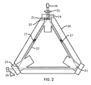
- FIG. 2 shows the much simpler solid state ring laser assembly where the gas discharge and electrodes have been replaced by a thin film of Nd doped silica deposited onto one of the multilayer dielectric mirrors and a laser diode illuminating and pumping the doped thin film through a focusing lens.
- FIG. 3 is a view of a gain mirror assembly showing a laser diode and lens pumping a thin film of Nd doped silica on top of a high reflectivity multilayer dielectric mirror.
- FIG. 4 shows an alternate way of delivering the pump light to the Nd doped thin film gain layer from a laser diode, located outside the laser housing, by using a fiber optic cable and connector.
- a conventional gas discharge ring laser shown in FIG. 1 is formed by attaching three high reflectivity multilayer dielectric mirrors 11 onto an ultra stable, low coefficient of expansion glass-ceramic body 10 which has appropriate cavities machined into it which behave as gain tubes 12 when filled with Helium-Neon gases 13 at low pressure and excited by an high-voltage, low-current electrical discharge 14 between a cathode 15 and a pair of anodes 16 .
- Two counter propagating beams of light 17 travel around the optical cavity through the gain tubes.
- This frequency difference can be measured by extracting minuscule amounts of light from each beam and overlaying them onto a pair of optical detectors using a simple prism and beam splitter arrangement 18 to form an optical fringe pattern.
- the rate of fringe motion (a beat frequency) across the detector pair is proportional to the rate of rotation and the direction the fringes move gives the direction of rotation.
- the solid state ring laser shown in FIG. 2 is comprised of three high reflectivity multilayer dielectric mirrors 21 mounted onto an ultrastable, machined and polished block of material 20 . These mirrors are positioned to define a closed loop optical path (the optical cavity), which passes through holes 22 in the block, and is traversed by counter propagating laser beams 27 when gain in the optical cavity exceeds loss.
- the frequencies of these laser beams are sensitive to rotation and the difference in the laser beam frequencies, which is proportional to rotation, is measured using a simple beam combining optical system and detector 28 just as in the conventional gas discharge ring laser.
- the solid state ring laser shown in FIG. 2 has no electrically excited gas discharge but has a thin, amorphous film 23 of Neodymium (Nd) doped silica (SiO 2 ) deposited on top of one or more of its multilayer dielectric mirrors 21 creating a gain mirror to supply optical amplification.
- Nd Neodymium
- SiO 2 Neodymium doped silica
- Light supplied by a 0.8 micron wavelength pump laser diode 26 and lens 25 assembly provides the light excitation energy 24 necessary to create the population inversion in Nd 3+ ions in the Nd doped thin film which is needed for lasing action 27 to occur at 1.06 micron wavelength in the optical cavity. This is a very simple design.
- the laser diode pumped Nd doped thin film 23 is the optical amplifier in the solid state ring laser and is the crux of this invention.
- Nd doped silica is an extremely high-gain medium at 1.06 microns wavelength and only needs to be a few wavelengths thick in order for lasing action to occur.
- the solid state gain medium must be very thin so as not to introduce errors into the rotation measurement process. This high gain together with the ultra low loss optical cavity of the ring laser is the absolutely ideal combination.
- laser diodes that are very efficient emitters at the 0.8 micron wavelength needed to pump the Nd 3+ ions in the doped Nd thin film and create the population inversion necessary to support laser oscillation at 1.06 microns wavelength and the thin film is very absorptive at 0.8 micron.
- Diodes that emit many milliwatts of power at 0.8 micron are readily available and are capable of operating the ring laser significantly above the threshold needed to achieve useful power output in the microwatt range.
- Nd doped silica has extremely high gain per unit length but has very small total gain in thin film form where the laser beam impinges on and passes through the face of the film, but this gain is still more than enough to create lasing action in an ultra low loss cavity.
- Nd doped silica typically contains about 5 ⁇ 10 20 Nd atoms/cm 3 .
- Typical high performance ring lasers have round trip optical cavity losses in the range of 100 to 200 ppm so this is a very favorable gain-to-loss ratio and assures laser oscillation will take place when using the gain mirror. Note that each laser beam traverses the Nd doped thin film gain media twice in a round trip pass of the optical cavity but because there are two lasers present (counter propagating beams) this analysis is valid.
- Amorphous Nd doped silica must be used in order to eliminate the high internal scattering that polycrystalline materials have which leads to a high lock-in threshold that reduces measurement accuracy of the laser gyro.
- FIG. 3 One design for the gain mirror is shown in FIG. 3 .
- a thin film of Nd doped silica 30 is deposited onto the outer layer 31 of a multilayer dielectric mirror.
- High reflectivity multilayer dielectric mirrors are formed by depositing alternate layers of high 31 and low 32 index of refraction material, each a quarter optical wavelength thick, onto a highly polished substrate 33 .
- Typical materials are TiO 2 and SiO 2 .
- the gain medium would preferably be deposited as an outer layer 30 which would be an integer number of half optical wavelengths thick so it would have no effect on passive mirror reflectivity and beam intensity would be maximum inside the gain material.
- the pump light 34 can be delivered to the Nd doped thin film of the gain mirror in several ways.
- One way is shown in FIG. 2 (and FIG. 3 ) where the laser diode 26 (and 36 ) and simple focusing optics 25 (and 35 ) are located inside the solid state ring laser housing. This is simple enough but places an undesirable heat source inside the housing and makes it difficult to replace the diode when needed.
- FIG. 4 Another approach shown in FIG. 4 is to locate the laser diode 46 outside the housing 48 and transmit the pump light 44 from the diode to the gain mirror 43 via a fiber optic cable 45 .
- a connector 47 can be used to pass the light through the housing wall 48 . This removes the diode and control electronics heat sources from inside the housing and makes the diode easily replaceable.
- Lasing operation with a Nd doped thin film SiO 2 gain mirror at 1.06 micron wavelength pumped by a laser diode at 0.8 micron wavelength is the easiest to achieve because this is a four level laser system.
- other laser operating wavelengths are possible by adjusting the multilayer dielectric mirror film thicknesses and changing the dopant material to change energy levels and adjusting the pump diode wavelength. For example, it may be desireable to have a laser operating closer to the visible portion of the optical spectrum where detectors are more sensitive.
- a low pressure gas is a near ideal optical transmission medium.
- the low pressure Helium-Neon discharge is a source of measurement error in the gas discharge ring laser gyro and limits the lifetime and reliability of the sensor. It also adds to high manufacturing costs.
- the solid state ring laser offers dramatically lower costs, increased reliability and lifetime, and enhanced performance.
- FIG. 1 and FIG. 2 The manufacturing benefits of the solid state ring laser can be seen by comparing FIG. 1 and FIG. 2 .
- the basic laser block is simplified by eliminating the electrodes and machined passages from the electrodes to the gain tubes. Also the polishing operations needed to form the surfaces needed to seal the electrodes to the block are eliminated.
- the expensive cathode made from exotic long-life material and an anode and anode fill tube are also eliminated.
- the gain tubes are no longer needed so the accuracy of this machining operation and its cost can also be reduced. These holes simply need to be passages for the counter propagating laser beams.
- the glass-ceramic material presently used for the ring laser body is no longer needed because without the need for Helium gas there is no concern over Helium gas loss through permeation through the material affecting lifetime. It could be replaced with ultra low expansion (ULE) fused silica, for example.
- UBE ultra low expansion
- This material is amorphous and has the potential for easier, quicker optical contact assembly of the mirrors to the block because glassy surfaces form better optical contact bonds than the polycrystalline surfaces of glass-ceramics, reducing assembly costs.
- the mirror substrates could also be made from amorphous ULE fused silica and may lead to reduced polishing costs, higher quality mirror substrates and enhanced optical contact seals.
- the solid state ring laser is significantly easier to assemble. Once the electrodes are bonded to the gas discharge ring laser block and the mirrors optically contacted to the block, the assembly must be attached to a highly specialized processing station. Here atmospheric gases must be vacuumed out and replaced with a low pressure mixture of special Helium and Neon isotopes. Before these gases are added, however, the cathode must be Oxygen processed to form a long-life electron emission surface. After the cathode is processed the Helium-Neon gas mixture is added and the laser must undergo a burn-in and clean-up procedure.
- the solid state ring laser makes it possible to simplify the electronics required for operation.
- the gas discharge requires complex start and run electronics. In order to start the gas discharge a very high, short duration voltage must be applied. After the discharge starts a high voltage must still be maintained between the cathode and anodes to keep the discharge running.
- the discharge must have symmetry to reduce gas flow induced measurement errors and thus the discharge control circuits must not only control the total current but the current balance between the two legs of the discharge. These high voltage circuits are problematic in the low voltage environment associated with modern digital circuitry.
- the solid state ring laser has no need for these high voltages and these circuits can be eliminated with significant cost savings.
- High voltage current control is replaced by low voltage control of the laser diode which may be outside the sensor housing.
- the solid state ring laser offers increased lifetime and reliability.
- the gas discharge is the main source of failures in the gas discharge ring laser assembly.
- the ultraviolet radiation and charged particles in the gas discharge degrade the mirror coating materials and increase mirror absorption leading to laser failure.
- the process that sustains the gas discharge involves ion bombardment of the cathode to release free electrons. This ion bombardment slowly buries gas molecules in the surface of the cathode and material sputtered off the cathode surface buries gas molecules on the walls of the discharge tubes. Both processes reduce Helium and Neon gas pressure in the laser, reduce gain and eventually lead to failure of the ring laser.
- the solid state ring laser offers enhanced performance. Rotation measurement accuracy is primarily determined by a fundamental lock-in threshold associated with coupling of the counter propagating light beams in the ring laser and by the gas flow instability associated with the gas discharge.
- the lock-in threshold establishes a minimum rotation rate that the sensor can measure and is associated with mirror imperfections and backscattering of the laser light from those imperfections.
- Photochromic effects where plasma (gas discharge) radiation (ultraviolet light) interacts with the counter propagating laser light beams to form very low level gratings in the mirrors also leads to coupling of the beams and lock-in.
- the solid state ring laser does not have this latter source of lock-in.
- the gas discharge does have properties that lead to instabilities in rotation measurements. Mainly the flowing of the Neon gaseous gain atoms due to the motion of free electrons and ionized particles in the plasma of the gas discharge creates a bias error. This flow is discharge current sensitive, temperature sensitive and magnetic field sensitive. Again the solid state ring laser does not have this error source.
- the Nd doped silica thin film gain mirror and pump laser diode assembly shown in FIG. 3 is an entity unto itself. It may be used in conjunction with any ultra low loss laser resonant cavity (ring, linear, out of plane, etc.) for special applications where stability may be paramount and low output power may be tolerated.
Landscapes
- Physics & Mathematics (AREA)
- Electromagnetism (AREA)
- Engineering & Computer Science (AREA)
- Optics & Photonics (AREA)
- Plasma & Fusion (AREA)
- Chemical & Material Sciences (AREA)
- Crystallography & Structural Chemistry (AREA)
- Radar, Positioning & Navigation (AREA)
- Remote Sensing (AREA)
- General Physics & Mathematics (AREA)
- Power Engineering (AREA)
- Gyroscopes (AREA)
- Lasers (AREA)
Abstract
Description
- Klass, P. J., Ring Laser Device Performs Rate Gyro Angular Sensor Functions, Aviation Week and Space Technology Magazine, Feb. 11, 1963
- Yariv, A., Introduction to Optical Electronics, 2nd Ed., New York, Holt, Rhinehart and Winston, 1976
- Rabeendran, N., New Approaches to Gyroscopic Lasers, PhD Thesis, University of Canterbury, 2013
γ=(N 2 −N 1)λ2 g(v)/8πn 2 t spont where γ is the fractional gain per cm
Also
-
- (N2−N1)=the population inversion density of the Nd3+ ions in number per cm3.
- λ=the lasing wavelength in cm.
- g(ν)=1/(Δν) is the gain curve line shape function with Δν the linewidth in hertz.
- n=the index of refraction for Nd doped SiO2.
- tspont=the spontaneous emission lifetime of the level 2 to level 1 transition in seconds.
(N 2 −N 1)=0.03×5×1020=1.5×10¹⁹/cm3.
Using the following data for Nd in silica
-
- λ=1.06 micron=1.06×10⁻⁴ cm
- n=1.5
- Δν=6×10¹² sec
- tspont=3×10⁻⁴ sec
we get a gain coefficient γ=1.5 cm−1
For a 3 wavelength thick (3 micron=3×10⁻⁴ cm) thin film the total gain per pass is G=1.5×3×10−4=4.5×10−4=450 ppm.
Claims (16)
Priority Applications (1)
| Application Number | Priority Date | Filing Date | Title |
|---|---|---|---|
| US15/626,106 US10148059B2 (en) | 2016-06-23 | 2017-06-17 | Gain mirror for solid state ring laser rotation sensors |
Applications Claiming Priority (2)
| Application Number | Priority Date | Filing Date | Title |
|---|---|---|---|
| US201662493119P | 2016-06-23 | 2016-06-23 | |
| US15/626,106 US10148059B2 (en) | 2016-06-23 | 2017-06-17 | Gain mirror for solid state ring laser rotation sensors |
Publications (2)
| Publication Number | Publication Date |
|---|---|
| US20170373458A1 US20170373458A1 (en) | 2017-12-28 |
| US10148059B2 true US10148059B2 (en) | 2018-12-04 |
Family
ID=60677963
Family Applications (1)
| Application Number | Title | Priority Date | Filing Date |
|---|---|---|---|
| US15/626,106 Active US10148059B2 (en) | 2016-06-23 | 2017-06-17 | Gain mirror for solid state ring laser rotation sensors |
Country Status (1)
| Country | Link |
|---|---|
| US (1) | US10148059B2 (en) |
Families Citing this family (4)
| Publication number | Priority date | Publication date | Assignee | Title |
|---|---|---|---|---|
| US20200056889A1 (en) * | 2018-08-17 | 2020-02-20 | Honeywell International Inc. | Enhanced solid-state gain medium for ring laser gyroscopes |
| US20200059062A1 (en) * | 2018-08-17 | 2020-02-20 | Honeywell International Inc. | Systems and methods for end pumped laser mirror stack assemblies |
| US10739137B2 (en) * | 2018-08-17 | 2020-08-11 | Honeywell International Inc. | Solid state ring laser gyroscope using rare-earth gain dopants in glassy hosts |
| US10907966B2 (en) * | 2019-06-18 | 2021-02-02 | Honeywell International Inc. | Solid state ring laser gyroscope having a primary cavity and a pumping cavity |
Citations (6)
| Publication number | Priority date | Publication date | Assignee | Title |
|---|---|---|---|---|
| US20040202222A1 (en) * | 2001-05-30 | 2004-10-14 | Jean Paul Pocholle | Solid state laser gyro comprising a resonator block |
| US20050040337A1 (en) * | 2001-09-12 | 2005-02-24 | Cox James A. | Tunable laser fluid sensor |
| US20070274361A1 (en) * | 2003-03-24 | 2007-11-29 | Calvez Stephane L D | Vertical-Cavity Semiconductor Optical Devices |
| US20080151961A1 (en) * | 2006-12-20 | 2008-06-26 | In Kim | Vertical cavity surface-emitting laser and method of fabricating the same |
| US20110064099A1 (en) * | 2009-09-11 | 2011-03-17 | Coherent, Inc. | Optically-pumped external-cavity surface-emitting semiconductor lasers with front-cooled gain-structures |
| US20140044226A1 (en) * | 2011-04-20 | 2014-02-13 | Logos Technologies Llc | Flexible Driver Laser for Inertial Fusion Energy |
-
2017
- 2017-06-17 US US15/626,106 patent/US10148059B2/en active Active
Patent Citations (6)
| Publication number | Priority date | Publication date | Assignee | Title |
|---|---|---|---|---|
| US20040202222A1 (en) * | 2001-05-30 | 2004-10-14 | Jean Paul Pocholle | Solid state laser gyro comprising a resonator block |
| US20050040337A1 (en) * | 2001-09-12 | 2005-02-24 | Cox James A. | Tunable laser fluid sensor |
| US20070274361A1 (en) * | 2003-03-24 | 2007-11-29 | Calvez Stephane L D | Vertical-Cavity Semiconductor Optical Devices |
| US20080151961A1 (en) * | 2006-12-20 | 2008-06-26 | In Kim | Vertical cavity surface-emitting laser and method of fabricating the same |
| US20110064099A1 (en) * | 2009-09-11 | 2011-03-17 | Coherent, Inc. | Optically-pumped external-cavity surface-emitting semiconductor lasers with front-cooled gain-structures |
| US20140044226A1 (en) * | 2011-04-20 | 2014-02-13 | Logos Technologies Llc | Flexible Driver Laser for Inertial Fusion Energy |
Also Published As
| Publication number | Publication date |
|---|---|
| US20170373458A1 (en) | 2017-12-28 |
Similar Documents
| Publication | Publication Date | Title |
|---|---|---|
| US10148059B2 (en) | Gain mirror for solid state ring laser rotation sensors | |
| US3718868A (en) | I{11 {11 {11 {11 INVERTED LAMB DIP STABILIZED He-Ne LASER | |
| EP2530504B1 (en) | High performance hollow-core optical-fiber filter for optical rotation sensing | |
| US9212912B1 (en) | Ring laser gyroscope on a chip with doppler-broadened gain medium | |
| US7907284B2 (en) | Enhanced scale factor ring laser gyroscope | |
| US20040202222A1 (en) | Solid state laser gyro comprising a resonator block | |
| US5430755A (en) | Pressure-equalized self-compensating discharge configuration for triangular ring laser gyroscopes | |
| US20110235047A1 (en) | Laser Gyro Having a Solid-State Amplifying Medium and an Optical Ring Cavity | |
| US4821281A (en) | Hollow cathode glow discharge ring laser angular rate sensor | |
| US5367377A (en) | Solid state split-gain multioscillator ring laser gyroscope | |
| Chopra | Optoelectronic Gyroscopes | |
| Woods et al. | Stable single-frequency carbon dioxide lasers | |
| JP2008516214A (en) | Solid laser gyro with stable scale factor | |
| Schreiber et al. | Rotation Sensing with Large Ring Lasers: Applications in Geophysics and Geodesy | |
| US4825260A (en) | Apparatus and method using amplification cells for ring laser gyroscope cavity length control | |
| JPS62217683A (en) | Ring laser | |
| US20260016355A1 (en) | Implementation of a dual fabry-perot photonic pressure sensor | |
| Roland et al. | Optical gyroscopes | |
| Digonnet | Status of broadband rare-earth doped fiber sources for FOG applications | |
| US9653873B1 (en) | Self-locking atomic emission laser with an intracavity atomic plasma as the resonance line seeder | |
| EP3800442A1 (en) | Ring laser gyroscopes with active volume bragg grating | |
| US3613026A (en) | Plasma tube impedance variation frequency stabilized gas laser | |
| Burns | Current status of fiber-optic gyroscopes | |
| GB2227878A (en) | Ring laser gyroscope | |
| US20060146335A1 (en) | Apparatus and method to facilitate laser gyroscope ionization |
Legal Events
| Date | Code | Title | Description |
|---|---|---|---|
| STCF | Information on status: patent grant |
Free format text: PATENTED CASE |
|
| FEPP | Fee payment procedure |
Free format text: MAINTENANCE FEE REMINDER MAILED (ORIGINAL EVENT CODE: REM.); ENTITY STATUS OF PATENT OWNER: MICROENTITY |
|
| FEPP | Fee payment procedure |
Free format text: SURCHARGE FOR LATE PAYMENT, MICRO ENTITY (ORIGINAL EVENT CODE: M3554); ENTITY STATUS OF PATENT OWNER: MICROENTITY |
|
| MAFP | Maintenance fee payment |
Free format text: PAYMENT OF MAINTENANCE FEE, 4TH YEAR, MICRO ENTITY (ORIGINAL EVENT CODE: M3551); ENTITY STATUS OF PATENT OWNER: MICROENTITY Year of fee payment: 4 |
|
| MAFP | Maintenance fee payment |
Free format text: PAYMENT OF MAINTENANCE FEE, 8TH YEAR, MICRO ENTITY (ORIGINAL EVENT CODE: M3552); ENTITY STATUS OF PATENT OWNER: MICROENTITY Year of fee payment: 8 |