US10146094B2 - Tunable achromatic waveplates - Google Patents
Tunable achromatic waveplates Download PDFInfo
- Publication number
- US10146094B2 US10146094B2 US14/818,443 US201514818443A US10146094B2 US 10146094 B2 US10146094 B2 US 10146094B2 US 201514818443 A US201514818443 A US 201514818443A US 10146094 B2 US10146094 B2 US 10146094B2
- Authority
- US
- United States
- Prior art keywords
- achromatic
- wave plate
- tunable
- retarders
- retarder
- Prior art date
- Legal status (The legal status is an assumption and is not a legal conclusion. Google has not performed a legal analysis and makes no representation as to the accuracy of the status listed.)
- Active
Links
- 239000000463 material Substances 0.000 claims abstract description 26
- 239000006185 dispersion Substances 0.000 claims abstract description 19
- 230000010287 polarization Effects 0.000 claims description 23
- 239000004973 liquid crystal related substance Substances 0.000 claims description 13
- 230000003595 spectral effect Effects 0.000 claims description 9
- 238000005305 interferometry Methods 0.000 claims description 7
- 230000010363 phase shift Effects 0.000 claims description 6
- 230000009977 dual effect Effects 0.000 claims description 4
- 238000003384 imaging method Methods 0.000 claims description 4
- 230000003098 cholesteric effect Effects 0.000 claims description 3
- 230000002452 interceptive effect Effects 0.000 claims description 2
- 239000000758 substrate Substances 0.000 claims 1
- 230000003287 optical effect Effects 0.000 abstract description 7
- 230000005540 biological transmission Effects 0.000 description 21
- 238000004088 simulation Methods 0.000 description 7
- 230000008859 change Effects 0.000 description 4
- 230000009471 action Effects 0.000 description 3
- 239000012141 concentrate Substances 0.000 description 3
- 230000005684 electric field Effects 0.000 description 3
- 239000011521 glass Substances 0.000 description 3
- 239000005387 chalcogenide glass Substances 0.000 description 2
- 230000007423 decrease Effects 0.000 description 2
- 230000001419 dependent effect Effects 0.000 description 2
- 239000005262 ferroelectric liquid crystals (FLCs) Substances 0.000 description 2
- 238000012634 optical imaging Methods 0.000 description 2
- 229910000530 Gallium indium arsenide Inorganic materials 0.000 description 1
- 239000004988 Nematic liquid crystal Substances 0.000 description 1
- 229910008062 Si-SiO2 Inorganic materials 0.000 description 1
- 229910006403 Si—SiO2 Inorganic materials 0.000 description 1
- 238000010521 absorption reaction Methods 0.000 description 1
- 230000006978 adaptation Effects 0.000 description 1
- 229910021417 amorphous silicon Inorganic materials 0.000 description 1
- 238000004873 anchoring Methods 0.000 description 1
- 238000013213 extrapolation Methods 0.000 description 1
- AMGQUBHHOARCQH-UHFFFAOYSA-N indium;oxotin Chemical compound [In].[Sn]=O AMGQUBHHOARCQH-UHFFFAOYSA-N 0.000 description 1
- 229940056932 lead sulfide Drugs 0.000 description 1
- 229910052981 lead sulfide Inorganic materials 0.000 description 1
- 238000004519 manufacturing process Methods 0.000 description 1
- 239000011159 matrix material Substances 0.000 description 1
- 238000005259 measurement Methods 0.000 description 1
- 239000010445 mica Substances 0.000 description 1
- 229910052618 mica group Inorganic materials 0.000 description 1
- 238000000386 microscopy Methods 0.000 description 1
- 238000012986 modification Methods 0.000 description 1
- 230000004048 modification Effects 0.000 description 1
- 239000002086 nanomaterial Substances 0.000 description 1
- 238000012014 optical coherence tomography Methods 0.000 description 1
- 238000005457 optimization Methods 0.000 description 1
- 229910021420 polycrystalline silicon Inorganic materials 0.000 description 1
- 230000001902 propagating effect Effects 0.000 description 1
- 239000010453 quartz Substances 0.000 description 1
- 239000012925 reference material Substances 0.000 description 1
- 230000004044 response Effects 0.000 description 1
- VYPSYNLAJGMNEJ-UHFFFAOYSA-N silicon dioxide Inorganic materials O=[Si]=O VYPSYNLAJGMNEJ-UHFFFAOYSA-N 0.000 description 1
- 239000010409 thin film Substances 0.000 description 1
Images


Classifications
-
- G—PHYSICS
- G02—OPTICS
- G02F—OPTICAL DEVICES OR ARRANGEMENTS FOR THE CONTROL OF LIGHT BY MODIFICATION OF THE OPTICAL PROPERTIES OF THE MEDIA OF THE ELEMENTS INVOLVED THEREIN; NON-LINEAR OPTICS; FREQUENCY-CHANGING OF LIGHT; OPTICAL LOGIC ELEMENTS; OPTICAL ANALOGUE/DIGITAL CONVERTERS
- G02F1/00—Devices or arrangements for the control of the intensity, colour, phase, polarisation or direction of light arriving from an independent light source, e.g. switching, gating or modulating; Non-linear optics
- G02F1/01—Devices or arrangements for the control of the intensity, colour, phase, polarisation or direction of light arriving from an independent light source, e.g. switching, gating or modulating; Non-linear optics for the control of the intensity, phase, polarisation or colour
- G02F1/13—Devices or arrangements for the control of the intensity, colour, phase, polarisation or direction of light arriving from an independent light source, e.g. switching, gating or modulating; Non-linear optics for the control of the intensity, phase, polarisation or colour based on liquid crystals, e.g. single liquid crystal display cells
- G02F1/133—Constructional arrangements; Operation of liquid crystal cells; Circuit arrangements
- G02F1/1333—Constructional arrangements; Manufacturing methods
- G02F1/1347—Arrangement of liquid crystal layers or cells in which the final condition of one light beam is achieved by the addition of the effects of two or more layers or cells
- G02F1/13471—Arrangement of liquid crystal layers or cells in which the final condition of one light beam is achieved by the addition of the effects of two or more layers or cells in which all the liquid crystal cells or layers remain transparent, e.g. FLC, ECB, DAP, HAN, TN, STN, SBE-LC cells
-
- G—PHYSICS
- G02—OPTICS
- G02B—OPTICAL ELEMENTS, SYSTEMS OR APPARATUS
- G02B5/00—Optical elements other than lenses
- G02B5/30—Polarising elements
- G02B5/3083—Birefringent or phase retarding elements
-
- G—PHYSICS
- G02—OPTICS
- G02F—OPTICAL DEVICES OR ARRANGEMENTS FOR THE CONTROL OF LIGHT BY MODIFICATION OF THE OPTICAL PROPERTIES OF THE MEDIA OF THE ELEMENTS INVOLVED THEREIN; NON-LINEAR OPTICS; FREQUENCY-CHANGING OF LIGHT; OPTICAL LOGIC ELEMENTS; OPTICAL ANALOGUE/DIGITAL CONVERTERS
- G02F1/00—Devices or arrangements for the control of the intensity, colour, phase, polarisation or direction of light arriving from an independent light source, e.g. switching, gating or modulating; Non-linear optics
- G02F1/01—Devices or arrangements for the control of the intensity, colour, phase, polarisation or direction of light arriving from an independent light source, e.g. switching, gating or modulating; Non-linear optics for the control of the intensity, phase, polarisation or colour
- G02F1/13—Devices or arrangements for the control of the intensity, colour, phase, polarisation or direction of light arriving from an independent light source, e.g. switching, gating or modulating; Non-linear optics for the control of the intensity, phase, polarisation or colour based on liquid crystals, e.g. single liquid crystal display cells
- G02F1/137—Devices or arrangements for the control of the intensity, colour, phase, polarisation or direction of light arriving from an independent light source, e.g. switching, gating or modulating; Non-linear optics for the control of the intensity, phase, polarisation or colour based on liquid crystals, e.g. single liquid crystal display cells characterised by the electro-optical or magneto-optical effect, e.g. field-induced phase transition, orientation effect, guest-host interaction or dynamic scattering
- G02F1/139—Devices or arrangements for the control of the intensity, colour, phase, polarisation or direction of light arriving from an independent light source, e.g. switching, gating or modulating; Non-linear optics for the control of the intensity, phase, polarisation or colour based on liquid crystals, e.g. single liquid crystal display cells characterised by the electro-optical or magneto-optical effect, e.g. field-induced phase transition, orientation effect, guest-host interaction or dynamic scattering based on orientation effects in which the liquid crystal remains transparent
- G02F1/1393—Devices or arrangements for the control of the intensity, colour, phase, polarisation or direction of light arriving from an independent light source, e.g. switching, gating or modulating; Non-linear optics for the control of the intensity, phase, polarisation or colour based on liquid crystals, e.g. single liquid crystal display cells characterised by the electro-optical or magneto-optical effect, e.g. field-induced phase transition, orientation effect, guest-host interaction or dynamic scattering based on orientation effects in which the liquid crystal remains transparent the birefringence of the liquid crystal being electrically controlled, e.g. ECB-, DAP-, HAN-, PI-LC cells
Definitions
- the invention is from the field of optics. Specifically the invention relates to the design of tunable achromatic wave plates.
- Achromatic wave plates are key components in many instruments and optical systems particularly in polarization control. Due to the importance of these components many investigators have presented various designs for achromatic quarter wave plates (AQWP) and achromatic half wave plates (AHWP) based on various optical principles [1-11].
- AQWP achromatic quarter wave plates
- HAWP achromatic half wave plates
- a cascade of two or more crystalline wave plates is a popular approach to design achromatic wave plates, while the wave plates in the cascade can be produced from the same or different materials with specific thickness and optical axis orientation of each one.
- the design of an achromatic wave plate in the visible range (using mica) formed from a combination of three retarders of the same material was proposed by Pancharatnam [1], in which the first and the third retarder are identical (thickness and orientation) while the one between has a specific thickness and orientation.
- a design composed of six retarders was presented in ref [2].
- Saha et al [3,4,5] presented different AQWP designs using crystalline quartz plates.
- the first design is a combination of three plates that can operate as AQWP and AHWP in the near infrared region by changing the orientation of the middle plate; the other two designs present an AQWP in the 500-700 nm region while one of them composed from four plates and the last from two plates.
- the invention is a tunable achromatic wave plate comprised of two or more retarders made of electrooptic or magnetooptic materials arranged at different orientations with respect to each other and at least one voltage source configured to tune the retardation dispersion of each of the retarders by applying an external electric or magnetic field to each retarder separately.
- At least two of the two or more retarders are made of different electrooptic or magnetooptic materials.
- At least one of the retarders is made of liquid crystal material.
- the material or mode of the liquid crystal material can be chosen from the group comprising: nematic, twisted nematic, vertically aligned, ferroelectric, cholesteric, hybrid aligned, chiral liquid crystals, flexoelectric, dual mode, and in-plane.
- Embodiments of the tunable achromatic wave plate of the invention can be comprised of two different retarders oriented with their optic axis perpendicular to each other and with the incident light polarized at 45 degrees to the optic axis of the first retarder.
- the spectral range over which the wave plate operates is tuned by changing the tilt angles of the retarders with respect to each other.
- the spectral range over which the wave plate operates is tuned by changing the voltage applied to each of the retarders.
- At least one of the retarders is a liquid crystal device having an alignment layer comprising a subwavelength grating.
- At least one of the retarders is comprised of pixels, thereby allowing the tunable achromatic wave plate to operate as an achromatic spatial light modulator.
- At least one of the retarders is comprised of an optically addressed spatial light modulator, thereby allowing the external field to be controlled by light.
- the tunable achromatic wave plate of the invention operates between two polarizers acting as an achromatic intensity switch.
- the first retarder is configured to act as a variable retarder and the second retarder is configured to act as a quarter wave plate; thereby causing the output of the tunable achromatic wave plate to act as a wavelength independent polarization rotator.
- the invention is an achromatic phase generator for a polarimetric imaging system composed of two tunable achromatic wave plates of the first aspect of the invention.
- the first achromatic wave plate is configured to operate as an achromatic full wave plate
- the second achromatic wave plate is configured to operate as one of an achromatic quarter, half, or full wave plate
- the output of the phase generator is Right circular polarization, linear Vertical polarization, or linear Horizontal polarization respectively.
- the first achromatic wave plate is configured to operate as an achromatic quarter wave plate
- the second achromatic wave plate is configured to operate as an achromatic half wave plate
- the output of the phase generator is Left circular polarization.
- An achromatic phase generator for a phase shift orthogonally polarized low coherence interferometry system composed of the tunable achromatic waveplate of the first aspect of the invention placed after the output of an orthogonally polarized interferometry system to generate achromatic phase shift between two interfering beams of the interferometry system.
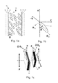
- FIG. 1 a schematically shows the structure of a nematic LC cell with anti-parallel alignment
- FIG. 1 b schematically shows the LC molecule and geometry of the optical axes
- FIG. 1 c schematically shows the device of the invention between two polarizers
- FIG. 2 shows retardation vs. wavelength of an E7 LC cell for different voltages
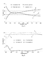
- FIG. 3 to FIG. 5 show the simulated transmission of an embodiment of the device of the invention between crossed and parallel polarizers for different values of tilt angle of the LC retarders, i.e. different voltages;
- FIG. 6 to FIG. 9 show experimentally measured transmission of an embodiment of the device of the invention between crossed and parallel polarizers for different values of tilt angle of the LC retarders, i.e. different voltages;
- FIG. 10 shows the simulated transmission of an embodiment of the device of the invention between crossed and parallel polarizers for the device of the invention comprising a third ideal nematic retarder.
- the invention is a new design of achromatic wave plates (AWP) based on two or more retarders made of electrooptic or magnetooptic materials such as liquid crystals.
- the AWPs of the invention operate as tunable achromatic quarter wave plates (AQWP), tunable achromatic half waveplates (AHWP) and tunable achromatic full wave plates (AFWP) by applying different voltages on each retarder over wide spectral bands.
- the novelty in the invention is to control the retardation dispersion by applying a suitable external field (electric or magnetic) to each retarder separately.
- Liquid crystals are birefringent materials which respond to small applied electric and magnetic fields. Hence the phase retardation of an optical wave propagating through them can be easily controlled.
- the effective extraordinary refractive index n e depends both on the refractive index parallel n ⁇ to the molecular axis and perpendicular to it n 51 as well as on the orientation angles of the LC molecules. Since the orientation angles of the LC molecules are voltage dependent, the effective birefringence and its dispersion will then be voltage dependent.
- FIG. 1 a The structure of a nematic LC cell with anti-parallel alignment at zero voltage is shown in FIG. 1 a , where the applied electric field is along the z axis.
- the cell 10 is built in a typical layered structure. From side to side the layers are: glass 12 , indium tin oxide (ITO) 14 , alignment layer 16 , LC material 18 comprised of LC molecules 20 , alignment layer 16 , ITO 14 and glass 12 .
- the layers are transparent.
- the ITO layers are conductive so applying the voltage drop between them imposes an electrical field on the LC material.
- the LC molecules with positive dielectric anisotropy tend to align parallel to the electric field, and as a result the angle ⁇ changes [12] thus changing the effective extraordinary refractive index and the retardation of the cell.
- FIG. 1 c schematically shows the device of the invention, which is composed of two nematic LC cells 10 with anti-parallel alignment oriented at 90 degrees to each other.
- Incident light represented by the broken arrow—is travelling along the z axis.
- a polarizer represented by the double headed arrow P—in front of the first LC cell
- an analyzer represented by the double headed arrow A—after the second LC cell that are not part of the device but are part of the experimental setup used for making measurements with the device.
- the optic axis of the first retarder is at 45 degrees to the polarizer axis.
- the Jones matrices represent a system which consists of a linear polarizer (at 0 degree with the x axis), the achromatic device composed from the two cells is arranged so that the optic axis of the first cell is at 45 degrees with respect to the polarizer P or the x-axis while the optic axis of the second cell is at ⁇ 45 degrees with respect to the x-axis and the analyzer A is at an arbitrary orientation ⁇ with the x-axis:
- J in represents the incident light after the polarizer
- A( ⁇ ) the analyzer matrix at angle ⁇ with respect to the polarizer
- Ret 1 and Ret 2 represent the matrices for the two retarders composing the device and ⁇ 1 , ⁇ 2 are their retardations respectively.
- FWP full waveplate
- the dispersion of each retarder is chosen so that the wavelength dependence is compensated at certain thicknesses to operate as AQWP, AHWP or AFWP.
- the voltage is used to tune the dispersion of the retardation of each retarder to obtain such compensation.
- a simulation of the retarders based on equation 1 has been performed using two different ideal nematic LC cells: the first uses Merck BL036 LC material with thickness of 27.23 ⁇ m and the second uses Merck E7 LC material with thickness of 49.51 ⁇ m.
- the change in the applied voltage is expressed in the simulation by changing the tilt angle ( ) of the molecules which causes a change of the birefringence (equation 1), or the retardation.
- FIG. 4 The possibility to tune the region of the AQWP to a different range by setting different pair of tilt angles (equivalently applying a different pair of voltages) in the same device is shown in FIG. 4 .
- Changing the tilt angle for the BL036 LC retarder to 35 degrees and the tilt angle for the E7 LC retarder to 46.26 degrees tunes the achromatic QWP to the wavelength region 435-645 nm with transmission variation of 10% ( ⁇ 0.06 ⁇ variation in retardation).
- FIG. 5 shows the experimentally measured transmission of the same device as in FIG. 3 and FIG. 4 with tilt angle for the BL036 LC of 2 degrees and 30.85 degrees for the E7 LC retarder showing that it operates as an AHWP in the range 535-1690 nm.
- Equation 4 the voltage normalized to the Frederick's threshold voltage, and ⁇ m ⁇ 0 at the threshold voltage.
- the values of the voltages from equation 4 are inaccurate because of the assumption of a uniform profile of ⁇ . Equations 4 and 5 give more accurate expression for ⁇ profile [14], for small angles ( ⁇ m ) up to 30°:
- z r z/d
- z in the distance across the cell and d is the thickness of the cell
- the first cell is a Merck BL036 LC retarder with thickness of 27.23 ⁇ 0.36 ⁇ m and the second cell is a Merck E7 LC retarder with thickness of 49.51 ⁇ 0.2 ⁇ m.
- the dashed lines represent the retardation levels.
- Line a represents the case of crossed polarizers while the case of parallel polarizers is represented by line b.
- the dashed lines represent the retardation values.
- the sharp decrease in the transmission below 460 nm is due to absorption of the LC materials, the ITO and the polarizers. This is an experimental demonstration of the AQWP at different spectral range 450-650 nm using the same device.
- Line a represents the transmission between crossed polarizers and line b the transmission between parallel polarizers.
- the device operates as an AHWP in the range 460-800 nm with transmission variation up to 10%.
- Line a represents the case of crossed polarizers while the case of parallel polarizers is represented by line b. This is an experimental demonstration for AFWP action in the range 470-1000 nm.
- the device as a tunable achromatic waveplate has been demonstrated herein, it is possible to generate other achromatic phase retardation values. Hence the device can in practice act as a tunable achromatic phase modulator useful for many applications.
- the orientation of two retarders with optics axis parallel to each other provides total retardation of ⁇ 2 + ⁇ 1 .
- This relation provides the opportunity to divide each thick retarder into two or more thinner retarders which decreases the response time of the device.
- Another utilization of this relation is to increase the achromatic region of the device by adding additional retarders to the basic two retarders with parallel orientation according to these basic retarders. As an example, if we add another LC retarder oriented parallel to the first retarder of the previously demonstrated device; the achromatic region will be extended.
- FIG. 10 shows the results of a simulation of an embodiment of the device of the invention comprising a third ideal nematic LC cell made from Merck BL036 LC material with thickness of 14.69 ⁇ m.
- FIG. 10 which is to be compared with FIG. 3 , shows the device operating as an extended AQWP with variation of 5% in transmission ( ⁇ 0.03 ⁇ in retardation) in the wavelength region of 510-930 nm.
- the second LC retarder with tilt angle of 17.74 degrees
- the third LC retarder with 27 degrees.
- FIG. 1 For embodiments of the invention use the same concept but with other LC modes or combinations of different LC devices based on different modes such as twisted nematic, vertically aligned, ferroelectric, cholesteric, hybrid aligned, chiral liquid crystals, flexoelectric, dual mode, in-plane and other modes known in the art. Combination of different modes and different LC materials is another important embodiment because it increases the chances to find the voltage combinations that give the desired achromatic range.
- Ferroelectric liquid crystals (FLCs) are faster devices and their use is important when dynamic control of the achromatic phase is important for example in broadband phase shift interferometry, interference microscopy and optical coherence tomography.
- Example of such an FLC mode that can give phase only modulation is the one presented by one of the inventors in ref [15], which includes special treatment of the boundaries so that the molecules at the boundaries are fixed.
- Alignment layers of the LC devices can also vary, for example nanostructured surfaces such as subwavelength gratings are known to align LCs and at the same time function also as polarizers.
- Subwavelength gratings have also the special dispersion property of their form birefringence which makes them useful for building passive non-tunable achromatic waveplates.
- One of the embodiments of this invention is to integrate subwavelength gratings and other nanostructures with form birefringence (examples include metallic gratings with Gaussian profile, glass gratings written with femtosecond lasers, etc.) into the LC devices in order to improve their functionality as tunable AWPs and to also function as alignment layers.
- Another embodiment of the device is to have at least one of its individual tunable retarders made of pixels so that an achromatic spatial light modulator (ASLM) is generated.
- ASLM achromatic spatial light modulator
- One important option of this embodiment is to have a small number of pixels of rectangular or annular shape in order to generate achromatic phase or amplitude masks used in optical imaging systems for improving the depth of field or the resolution.
- Another important option is to use such achromatic SLM to change the focus of an optical imaging system without dependence on the wavelength.
- One important application is as an achromatic phase mask located near the image plane of orthogonal polarization interferometer or interference microscope to give 3 or 4 different phase shifts between the two orthogonal polarizations; hence 3D phase image can be obtained without any scanning.
- Another embodiment of the device is one in which the external fields are controlled by light, for example by having at least one of the individual retarders made as an optically addressed spatial light modulator (OASLM).
- OASLM optically addressed spatial light modulator
- a photosensor layer is used in conjunction with the LC layer so that when light is incident on the photosensor, it changes the voltage drop on the LC layer because of the generated photocurrent or the photoinduced change in the resistivity or capacitance of the photosensor layer.
- the writing light can then be in a different spectral region or polarization than the light to be modulated and the device can operate in reflection or in transmission modes.
- photosensors include crystalline or polycrystalline Si, hydrogenated amorphous Si, lead sulfide, InGaAs photodiodes, PbS, chalcogenide glass thin films and more. Chalcogenide glass has also been shown by the group of one of the inventors to act as a photoalignment layer in addition to its action as a photosensor [16].
- Another embodiment of the device is to have it acting as an achromatic switch when operated between two polarizers as demonstrated in FIG. 8 and FIG. 9 , which For example shows a case in which switching of the transmission between ON and OFF is achieved over a wideband.
- Another embodiment of the device is as a wavelength independent polarization rotator, when the first retarder is acting as a variable retarder while the second retarder is acting as a quarter waveplate (QWP).
- QWP quarter waveplate
- the vertically incident polarized light will be rotated by half of the retardation of the first cell. It is possible to improve the polarization rotator by having the QWP to be achromatic in which case the number of the active voltage channels is reduced.
- Another embodiment of the device is to build an achromatic phase generator for a polarimetric imaging system that generates linear Vertical polarization (V), linear Horizontal polarization (H), Right circular polarization (R) and Left circular polarization (L).
- This phase generator is composed of two achromatic devices.
- the first device acts as AFWP and the second device act as AQWP, AHWP or AFWP the output of the polarization generator is R, V and H polarization respectively.
- the first device acts as AQWP and the second device acts as AHWP
- the output of the phase generator is L polarization.
Landscapes
- Physics & Mathematics (AREA)
- Nonlinear Science (AREA)
- General Physics & Mathematics (AREA)
- Optics & Photonics (AREA)
- Chemical & Material Sciences (AREA)
- Crystallography & Structural Chemistry (AREA)
- Mathematical Physics (AREA)
- Liquid Crystal (AREA)
- Spectroscopy & Molecular Physics (AREA)
Abstract
Description
ϑm=ϑ0+(π/2−ϑ0)√{square root over (1−1/Vr 2)} (4)
and equation 6 describes the profile for ϑm>30°:
Γ=2π∫0 1(n e(ϑ(z r))−n o)dz r/λ (7)
- 1. S. Pancharatnam, Proc. Indian Acad. Sci. 41A, 137-144 (1955).
- 2. J. B. Masson and G. Gallot, OPTICS LETTERS, Vol. 31, No. 2, (2006).
- 3. A. Saha, K. Bhattacharya and A. K. Chakraborty, Optical Engineering 50(3), 034004 (2011).
- 4. A. Saha, K. Bhattacharya and A. K. Chakraborty, Optical Engineering 51(1), 013001 (January 2012).
- 5. A. Saha, K. Bhattacharya and A. K. Chakraborty, APPLIED OPTICS, Vol. 51, No. 12, (2012).
- 6. S. Shen, J. She, and T. Tao, J Opt Soc Am. A, Vol. 22, No. 5 (2005).
- 7. H. Kikuta, Y. Ohira, and K. Iwata, APPLIED OPTICS. Vol. 36, No. 7. (1997).
- 8. G. P. Nordin and P. C. Deguzman, OPTICS EXPRES, Vol. 5, No. 8, (1999).
- 9. K. Guo-Guo, T. Qiao-Feng, and J. Guo-Fan, CHIN PHYS LETT, Vol. 26, No. 7 (2009).
- 10. G. Kang, Q. Tan, X. Wang and G. Jin, OPTICS EXPRESS, Vol. 18, No. 2, (2010).
- 11. R. M. A. Azzam and C. L. Spinu, J. Opt. Soc. Am A, Vol. 21, No. 10, (2004).
- 12. I. Abdulhalim, R. Moses and R. Sharon, ACTA PHYSICA POLONICA A, No. 5, Vol. 112 (2007).
- 13. M. Wahle and H. S. Kitzerow, OPTICS EXPRESS, Vol. 22, No. 1, (2014).
- 14. I. Abdulhalim and D. Menashe, Liquid Crystals, Vol. 37, No. 2, 233-239 (2010).
- 15. I. Abdulhalim, Continuous Phase-Only or Amplitude Light Modulation using Ferroelectric Liquid Crystals with Fixed Boundary Orientations, Optic Communi, 108, 219 (1994).
- 16. Miri Gelbaor Kirzhner, Matvey Klebanov, Victor Lyubin, Neil Collings, and I. Abdulhalim, High resolution optically addressed spatial light modulator based on nematic liquid crystal and nano-dimensional chalcogenide glass photosensor, Optics Letters 39, 2048 (2014).
Claims (15)
Priority Applications (1)
| Application Number | Priority Date | Filing Date | Title |
|---|---|---|---|
| US14/818,443 US10146094B2 (en) | 2014-08-17 | 2015-08-05 | Tunable achromatic waveplates |
Applications Claiming Priority (2)
| Application Number | Priority Date | Filing Date | Title |
|---|---|---|---|
| US201462038273P | 2014-08-17 | 2014-08-17 | |
| US14/818,443 US10146094B2 (en) | 2014-08-17 | 2015-08-05 | Tunable achromatic waveplates |
Publications (2)
| Publication Number | Publication Date |
|---|---|
| US20160048049A1 US20160048049A1 (en) | 2016-02-18 |
| US10146094B2 true US10146094B2 (en) | 2018-12-04 |
Family
ID=55302092
Family Applications (1)
| Application Number | Title | Priority Date | Filing Date |
|---|---|---|---|
| US14/818,443 Active US10146094B2 (en) | 2014-08-17 | 2015-08-05 | Tunable achromatic waveplates |
Country Status (1)
| Country | Link |
|---|---|
| US (1) | US10146094B2 (en) |
Cited By (1)
| Publication number | Priority date | Publication date | Assignee | Title |
|---|---|---|---|---|
| RU239108U1 (en) * | 2025-04-30 | 2025-11-24 | Общество с ограниченной ответственностью "Терагерцовая фотоника" | Achromatic wave plates for the terahertz range with multiple cutoff frequencies |
Families Citing this family (6)
| Publication number | Priority date | Publication date | Assignee | Title |
|---|---|---|---|---|
| EP3252529A1 (en) * | 2016-05-30 | 2017-12-06 | INTA, Instituto Nacional de Technica Aeroespacial | Achromatic liquid crystal variable optical retarder |
| TWI592717B (en) | 2016-07-13 | 2017-07-21 | 國立清華大學 | Tunable terahertz achromatic wave plate and a terahertz achromatic range tuning method |
| JP6727657B2 (en) * | 2017-11-06 | 2020-07-22 | 独立行政法人国立高等専門学校機構 | Liquid crystal tunable filter |
| US10712577B1 (en) * | 2017-12-05 | 2020-07-14 | Facebook Technologies, Llc | Electronically tunable polarizing beam splitter |
| CN114935843B (en) * | 2022-06-27 | 2023-11-14 | 曲阜师范大学 | A terahertz tunable polarizing wave plate and its control method |
| CN119644620A (en) * | 2024-12-18 | 2025-03-18 | 电子科技大学 | Composite liquid crystal achromatic wave plate |
Citations (6)
| Publication number | Priority date | Publication date | Assignee | Title |
|---|---|---|---|---|
| US5592314A (en) * | 1993-12-02 | 1997-01-07 | Yazaki Corporation | Tunable wavelength filter formed by 2 lcds in series having opposite twist angles of n*π/2 and a dielectric mirror layer on each substrate |
| US6141069A (en) * | 1994-07-27 | 2000-10-31 | University Technology Corporation | Liquid crystal phase modulator using a ferroelectric liquid crystal with a rotatable axis and cholesteric circular polarizers |
| US6380997B1 (en) * | 1995-04-07 | 2002-04-30 | Colorlink, Inc. | Achromatic polarization inverters for displaying inverse frames in DC balanced liquid crystal displays |
| US20040239869A1 (en) * | 2003-06-02 | 2004-12-02 | Cavanaugh Shanti A. | Narrow band tunable filter with integrated detector |
| US20060262396A1 (en) * | 2005-05-19 | 2006-11-23 | Smith Irl W | Optical diplexer with liquid crystal tunable waveplate |
| US20140362331A1 (en) * | 2013-03-15 | 2014-12-11 | Chemlmage Corporation | Short-Wavelength Infrared (SWIR) Multi-Conjugate Liquid Crystal Tunable Filter |
-
2015
- 2015-08-05 US US14/818,443 patent/US10146094B2/en active Active
Patent Citations (6)
| Publication number | Priority date | Publication date | Assignee | Title |
|---|---|---|---|---|
| US5592314A (en) * | 1993-12-02 | 1997-01-07 | Yazaki Corporation | Tunable wavelength filter formed by 2 lcds in series having opposite twist angles of n*π/2 and a dielectric mirror layer on each substrate |
| US6141069A (en) * | 1994-07-27 | 2000-10-31 | University Technology Corporation | Liquid crystal phase modulator using a ferroelectric liquid crystal with a rotatable axis and cholesteric circular polarizers |
| US6380997B1 (en) * | 1995-04-07 | 2002-04-30 | Colorlink, Inc. | Achromatic polarization inverters for displaying inverse frames in DC balanced liquid crystal displays |
| US20040239869A1 (en) * | 2003-06-02 | 2004-12-02 | Cavanaugh Shanti A. | Narrow band tunable filter with integrated detector |
| US20060262396A1 (en) * | 2005-05-19 | 2006-11-23 | Smith Irl W | Optical diplexer with liquid crystal tunable waveplate |
| US20140362331A1 (en) * | 2013-03-15 | 2014-12-11 | Chemlmage Corporation | Short-Wavelength Infrared (SWIR) Multi-Conjugate Liquid Crystal Tunable Filter |
Non-Patent Citations (16)
| Title |
|---|
| Abdulhalim and D. Menashe, Liquid Crystals, vol. 37, No. 2, 233-239 (2010). |
| Abdulhalim, Continuous Phase-Only or Amplitude Light Modulation using Ferroelectric Liquid Crystals with Fixed Boundary Orientations, Optic Communi, 108, 219 (1994). |
| Abdulhalim, R. Moses and R. Sharon, Acta Physica Polonica A, No. 5, vol. 112 (2007). |
| G. Kang, Q. Tan, X. Wang and G. Jin, Optics Express, vol. 18, No. 2, (2010). |
| G. P. Nordin and P. C. Deguzman, Optics Expres, vol. 5, No. 8, (1999). |
| H. Kikuta, Y. Ohira, and K. Iwata, Applied Optics. vol. 36, No. 7. (1997). |
| J. B. Masson and G. Gallot, Optics Letters, vol. 31, No. 2, (2006). |
| K. Guo-Guo, T. Qiao-Feng, and J. Guo-Fan, Chin Phys Lett, vol. 26, No. 7 (2009). |
| M. Wahle and H. S. Kitzerow, Optics Express, vol. 22, No. 1, (2014). |
| Miri Gelbaor Kirzhner, Matvey Klebanov, Victor Lyubin, Neil Collings, and I. Abdulhalim, High resolution optically addressed spatial light modulator based on nematic liquid crystal and nanodimensional chalcogenide glass photosensor, Optics Letters 39, 2048 (2014). |
| R. M. A. Azzam and C. L. Spinu, J. Opt. Soc. Am A, vol. 21, No. 10, (2004). |
| S. Pancharatnam, Proc. Indian Acad. Sci. 41A, 137-144 (1955). |
| S. Shen, J. She, and T. Tao, J Opt Soc Am. A, vol. 22, No. 5 (2005). |
| Saha, K. Bhattacharya and A. K. Chakraborty, Applied Optics, vol. 51, No. 12, (2012). |
| Saha, K. Bhattacharya and A. K. Chakraborty, Optical Engineering 50(3), 034004 (2011). |
| Saha, K. Bhattacharya and A. K. Chakraborty, Optical Engineering 51(1), 013001 (Jan. 2012). |
Cited By (1)
| Publication number | Priority date | Publication date | Assignee | Title |
|---|---|---|---|---|
| RU239108U1 (en) * | 2025-04-30 | 2025-11-24 | Общество с ограниченной ответственностью "Терагерцовая фотоника" | Achromatic wave plates for the terahertz range with multiple cutoff frequencies |
Also Published As
| Publication number | Publication date |
|---|---|
| US20160048049A1 (en) | 2016-02-18 |
Similar Documents
| Publication | Publication Date | Title |
|---|---|---|
| US10146094B2 (en) | Tunable achromatic waveplates | |
| Ren et al. | Tunable-focus microlens arrays using nanosized polymer-dispersed liquid crystal droplets | |
| US11567381B2 (en) | Spectral and phase modulation tunable birefringence devices | |
| US9690161B2 (en) | Field induced heliconical structure of cholesteric liquid crystal | |
| Otón et al. | Liquid-crystal phase-only devices | |
| Ung et al. | Towards a rapid terahertz liquid crystal phase shifter: Terahertz in-plane and terahertz out-plane (TIP-TOP) switching | |
| US11774824B2 (en) | Spectral and phase modulation tunable birefringence devices | |
| US10353245B2 (en) | Tunable terahertz achromatic wave plate and a terahertz achromatic range tuning method | |
| US8570460B2 (en) | Electronically-controllable polarization independent liquid crystal optical medium and devices using same | |
| Kesaev et al. | Modulation of unpolarized light in planar-aligned subwavelength-pitch deformed-helix ferroelectric liquid crystals | |
| Jewell et al. | Tuneable Fabry–Perot etalon for terahertz radiation | |
| Zografopoulos et al. | Design of switchable guided-mode resonant filters in zenithal-bistable liquid-crystal gratings | |
| Feng et al. | Positive-negative tunable cylindrical liquid crystal lenses | |
| Sasaki et al. | Liquid crystal cells with subwavelength metallic gratings for transmissive terahertz elements with electrical tunability | |
| Schirmer et al. | Liquid crystal phase retarder with broad spectral range | |
| TWI647523B (en) | Electro-optical phase modulator | |
| Ren et al. | Flat polymeric microlens array | |
| Gilman et al. | Properties of tunable nematic liquid crystal retarders | |
| Xu et al. | Real-time angular sensitivity compensation of guided-mode resonance filter | |
| Kanseri et al. | Broadband spectral shaping using nematic liquid crystal | |
| Kar et al. | Total internal reflection dependent polarization preserver and dynamic electro-optically controllable polarizer using liquid crystal | |
| Nasir et al. | Electro-tunable optical cavity filters in near-infrared regime | |
| Kasyanova et al. | Switchable optical metasurfaces based on nematic liquid crystal | |
| US9612480B2 (en) | Method of producing a phase device based on a twisted liquid crystal having optimized structure operating under unpolarized light | |
| Isaacs et al. | Fiber-coupled polarization independent liquid crystal Fabry–Perot tunable filter |
Legal Events
| Date | Code | Title | Description |
|---|---|---|---|
| AS | Assignment |
Owner name: B. G. NEGEV TECHNOLOGIES AND APPLICATIONS LTD, AT Free format text: ASSIGNMENT OF ASSIGNORS INTEREST;ASSIGNORS:ABDULHALIM, IBRAHIM;ABU LEIL, MARWAN;REEL/FRAME:039873/0420 Effective date: 20160831 |
|
| AS | Assignment |
Owner name: ABDULHALIM, IBRAHIM, ISRAEL Free format text: ASSIGNMENT OF ASSIGNORS INTEREST;ASSIGNOR:B.G. NEGEV TECHNOLOGIES AND APPLICATIONS LTD., AT BEN-GURION UNVERSITY;REEL/FRAME:043074/0329 Effective date: 20170717 Owner name: ABU LEIL, MARWAN, ISRAEL Free format text: ASSIGNMENT OF ASSIGNORS INTEREST;ASSIGNOR:B.G. NEGEV TECHNOLOGIES AND APPLICATIONS LTD., AT BEN-GURION UNVERSITY;REEL/FRAME:043074/0329 Effective date: 20170717 |
|
| STCF | Information on status: patent grant |
Free format text: PATENTED CASE |
|
| MAFP | Maintenance fee payment |
Free format text: PAYMENT OF MAINTENANCE FEE, 4TH YR, SMALL ENTITY (ORIGINAL EVENT CODE: M2551); ENTITY STATUS OF PATENT OWNER: SMALL ENTITY Year of fee payment: 4 |