US10145220B2 - Inflow control apparatus, methods, and systems - Google Patents
Inflow control apparatus, methods, and systems Download PDFInfo
- Publication number
- US10145220B2 US10145220B2 US14/781,685 US201414781685A US10145220B2 US 10145220 B2 US10145220 B2 US 10145220B2 US 201414781685 A US201414781685 A US 201414781685A US 10145220 B2 US10145220 B2 US 10145220B2
- Authority
- US
- United States
- Prior art keywords
- screen
- sinh
- sand
- cosh
- conduit
- Prior art date
- Legal status (The legal status is an assumption and is not a legal conclusion. Google has not performed a legal analysis and makes no representation as to the accuracy of the status listed.)
- Expired - Fee Related, expires
Links
Images


Classifications
-
- E—FIXED CONSTRUCTIONS
- E21—EARTH OR ROCK DRILLING; MINING
- E21B—EARTH OR ROCK DRILLING; OBTAINING OIL, GAS, WATER, SOLUBLE OR MELTABLE MATERIALS OR A SLURRY OF MINERALS FROM WELLS
- E21B43/00—Methods or apparatus for obtaining oil, gas, water, soluble or meltable materials or a slurry of minerals from wells
- E21B43/02—Subsoil filtering
- E21B43/08—Screens or liners
- E21B43/082—Screens comprising porous materials, e.g. prepacked screens
-
- E—FIXED CONSTRUCTIONS
- E21—EARTH OR ROCK DRILLING; MINING
- E21B—EARTH OR ROCK DRILLING; OBTAINING OIL, GAS, WATER, SOLUBLE OR MELTABLE MATERIALS OR A SLURRY OF MINERALS FROM WELLS
- E21B43/00—Methods or apparatus for obtaining oil, gas, water, soluble or meltable materials or a slurry of minerals from wells
- E21B43/12—Methods or apparatus for controlling the flow of the obtained fluid to or in wells
- E21B43/121—Lifting well fluids
- E21B43/124—Adaptation of jet-pump systems
-
- E21B47/124—
-
- E—FIXED CONSTRUCTIONS
- E21—EARTH OR ROCK DRILLING; MINING
- E21B—EARTH OR ROCK DRILLING; OBTAINING OIL, GAS, WATER, SOLUBLE OR MELTABLE MATERIALS OR A SLURRY OF MINERALS FROM WELLS
- E21B47/00—Survey of boreholes or wells
- E21B47/26—Storing data down-hole, e.g. in a memory or on a record carrier
-
- G—PHYSICS
- G05—CONTROLLING; REGULATING
- G05B—CONTROL OR REGULATING SYSTEMS IN GENERAL; FUNCTIONAL ELEMENTS OF SUCH SYSTEMS; MONITORING OR TESTING ARRANGEMENTS FOR SUCH SYSTEMS OR ELEMENTS
- G05B17/00—Systems involving the use of models or simulators of said systems
-
- G—PHYSICS
- G05—CONTROLLING; REGULATING
- G05B—CONTROL OR REGULATING SYSTEMS IN GENERAL; FUNCTIONAL ELEMENTS OF SUCH SYSTEMS; MONITORING OR TESTING ARRANGEMENTS FOR SUCH SYSTEMS OR ELEMENTS
- G05B19/00—Program-control systems
- G05B19/02—Program-control systems electric
- G05B19/18—Numerical control [NC], i.e. automatically operating machines, in particular machine tools, e.g. in a manufacturing environment, so as to execute positioning, movement or co-ordinated operations by means of program data in numerical form
- G05B19/416—Numerical control [NC], i.e. automatically operating machines, in particular machine tools, e.g. in a manufacturing environment, so as to execute positioning, movement or co-ordinated operations by means of program data in numerical form characterised by control of velocity, acceleration or deceleration
-
- G06F17/5009—
-
- G—PHYSICS
- G06—COMPUTING OR CALCULATING; COUNTING
- G06F—ELECTRIC DIGITAL DATA PROCESSING
- G06F30/00—Computer-aided design [CAD]
- G06F30/20—Design optimisation, verification or simulation
-
- E—FIXED CONSTRUCTIONS
- E21—EARTH OR ROCK DRILLING; MINING
- E21B—EARTH OR ROCK DRILLING; OBTAINING OIL, GAS, WATER, SOLUBLE OR MELTABLE MATERIALS OR A SLURRY OF MINERALS FROM WELLS
- E21B2200/00—Special features related to earth drilling for obtaining oil, gas or water
- E21B2200/02—Down-hole chokes or valves for variably regulating fluid flow
-
- G—PHYSICS
- G05—CONTROLLING; REGULATING
- G05B—CONTROL OR REGULATING SYSTEMS IN GENERAL; FUNCTIONAL ELEMENTS OF SUCH SYSTEMS; MONITORING OR TESTING ARRANGEMENTS FOR SUCH SYSTEMS OR ELEMENTS
- G05B2219/00—Program-control systems
- G05B2219/30—Nc systems
- G05B2219/37—Measurements
- G05B2219/37371—Flow
Definitions
- ICD Inflow Control Devices
- FIG. 1 is a side, cut-away view of an apparatus according to various embodiments of the invention.
- FIG. 2 is a side, cut-away diagram of fluids flowing in the vicinity of an ICD apparatus, according to various embodiments of the invention.
- FIG. 3 is a side, cut-away diagram of simulated fluid pressure in the vicinity of an ICD apparatus, according to various embodiments of the invention.
- FIG. 4 is a simplified fluid flow diagram for an analytical solution to the total flow rate of a fluid in the vicinity of an ICD apparatus, according to various embodiment of the invention.
- FIG. 5 is a graph comparing a conventional numerical solution to an analytical solution of the predicted fluid pressure distribution profiles in the vicinity of an ICD apparatus, according to various embodiment of the invention.
- FIG. 6 is a graph comparing a conventional numerical solution to an analytical solution of the predicted (normalized) fluid pressure distribution profiles in the vicinity of an ICD apparatus, according to various embodiment of the invention.
- FIG. 7 is a graph comparing a conventional numerical solution to an analytical solution with respect to the total flow rate and normalized gap width of a fluid moving in the vicinity of an ICD apparatus, according to various embodiment of the invention.
- FIG. 8 illustrates multiple types of apparatus according to various embodiments, along with a horizontal well 810 in which an ICD apparatus has been placed.
- FIG. 9 is a flow chart illustrating several methods according to various embodiments of the invention.
- FIG. 10 is a block diagram of an article according to various embodiments of the invention.
- ICD design can take into account the conditions, such as flow rates, viscosities, etc. that are expected in a particular well, and the results of flow simulations can be available much more quickly than is possible with conventional approaches, to provide more immediate guidance with respect to ICD component design.
- a method for simulating fluid flow in the vicinity of an ICD is disclosed.
- the results obtained using the analytical solution are very close to those provided by much more computationally intense numerical simulations, such as those using the Finite Difference Method.
- the methods described herein can operate to combine flow through the device with the flow in the porous media surrounding the device, to optimize ICD screen parameters.
- the screen area and gap height between the screen and the base conduit can be selected relatively quickly, reducing development cost and the risk of improperly-sized device deployment as the same time. This provides an overall improvement in the modeling of ICD performance via numerical simulators that are commonly used by petroleum engineers.
- the analytical expressions for pressure/flow field around the ICD that are developed herein can be included in conventional numerical simulators, such as those that operate as part of the NEToolTM, QuickLook®, and Nexus® software packages, among others. As a result the speed of completion modeling can be dramatically improved.
- conventional numerical simulators such as those that operate as part of the NEToolTM, QuickLook®, and Nexus® software packages, among others.
- FIG. 1 is a side, cut-away view of an apparatus 100 according to various embodiments of the invention.
- the apparatus 100 comprises an ICD.
- the outer surface of the apparatus 100 that is not covered by the screen 120 may comprise a shroud 130 and the base conduit 140 , which are both substantially impenetrable to the fluids 110 (except for the orifices 160 in the base conduit 140 ).
- the base conduit 140 may have threads or other coupling mechanisms 144 located proximate to each of the end ports 148 .
- the flow of fluids 110 may result in filling the annulus 804 between the apparatus 100 and the formation with sand or other debris.
- the annulus 860 may also be deliberately filled with porous material, such as gravel. When the annulus 860 fills in this manner, the flow of fluid 110 is usually directed to the nearest screen surface.
- FIG. 2 is a side, cut-away diagram of fluids 110 flowing in the vicinity of an ICD apparatus 100 , according to various embodiments of the invention.
- the screen 120 comprises a mesh, separated from the underlying surface of the base conduit (e.g., tubing) 140 by a gap 250 of width h, which in some embodiments is determined by the height of the ribs 146 (see FIG. 1 ) that serve to space the screen 120 apart from the outer surface of the wall 142 of the base conduit 140 .
- the gap 250 At one end of the gap 250 there are the entry orifices for receiving the fluid 110 (e.g., production fluid) entering the screen 120 .
- the flow in the gap 250 is directed mostly axially (in the direction r) and is described by the lubrication theory equations:
- Equations (1) and (2) are arranged to imply that there is no fluid flowing from the wellbore through the shroud wall.
- equation (1) as a de facto boundary condition for solving the Laplace equation (2) renders resolving the flow details inside the under-screen gap 250 and substantially accelerates the solution process.
- FIG. 3 is a side, cut-away diagram of simulated fluid flow pressure in the vicinity of an ICD apparatus 100 , according to various embodiments of the invention.
- the isobars of pressure are nearly vertical, implying that the variation of pressure in that layer is negligible. This property can be used to build an analytical solution for the pressure distribution.
- FIG. 4 is a simplified fluid flow diagram for an analytical solution to the total flow rate of a fluid in the vicinity of an ICD apparatus 100 , according to various embodiment of the invention. Due to the high aspect ratio of the ratio L/r s in the formation, the flow of fluid 110 is directed mostly radially, so the steady-state pressure distribution adheres closely to a logarithmic expression. And since the pressure drop across the screen in the sand layer is assumed to be negligible, the pressure distribution in the layer can be described by the set of equations
- the first equation in the set of equations (3) represents the sum of momentum equations for the gap 250 under the screen and the sand layer above the screen, while the second equation in the set of equations (3) represents the momentum equation of the sand layer adjacent to the shroud.
- the explicit form of the inflow densities in the right-hand sides of the equations in the set (3) is based on assumption of a steady-state logarithmic pressure profile in the formation, with p B equal to pressure at the boundary between the sand and the formation. It is assumed that the inlet pressure p in of the apparatus 100 is known.
- the last equation in the set (3) represents the periodicity conditions, implying a smooth matching of distributions p 1 (z) and p 2 (z) at the beginning and the end (e.g., at the two ports) of the apparatus 100 .
- the set of equations (3) can be solved to yield the analytical solution for pressure distribution in the sand layer, as the set of equations (4) below:
- Equation (6) is reduced to equation (4) for the pressure distribution in the sand layer.
- FIG. 5 is a graph 512 comparing a conventional numerical solution to an analytical solution of the predicted fluid pressure distribution profiles in the vicinity of an ICD apparatus, according to various embodiment of the invention.
- this graph 512 the numerically and analytically calculated profiles of pressure in the sand layer are shown in the lower portion of the graph.
- the numerically and analytically calculated profiles of pressure at 2 m from the well axis are shown in the upper portion of the graph 512 .
- a relatively narrow gap width h of 0.0005 m is used.
- FIG. 6 is a graph 612 comparing a conventional numerical solution to an analytical solution of the predicted (normalized) fluid pressure distribution profiles in the vicinity of an ICD apparatus, according to various embodiment of the invention.
- this graph 612 the numerically and analytically calculated profiles of pressure in the sand layer are shown in the lower portion of the graph.
- the numerically and analytically calculated profiles of pressure at 2 m from the well axis are shown in the upper portion of the graph 612 . In this case, a wider gap width h of 0.005 m is used.
- FIGS. 5 and 6 thus facilitate the comparison of the pressure distributions predicted by the analytical solution represented by Equations (4)-(6) and direct numerical simulations that are used to solve Equations (1) and (2).
- the parameters of the formation for these calculations are the same as those used in the calculations that produced the graphic representation of pressure in FIG. 3 .
- the analytical and numerical results are in remarkably good agreement, particularly in the sand layer, which implies that the set of Equations (4)-(6) can be used for nearly instant analysis of the flow in the vicinity of an apparatus 100 , such as an ICD located in a well.
- Equation (6) yields the following equation as Equation (7), representing the total flow rate to an apparatus 100 , realized as an ICD section of a piping string:
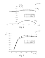
- FIG. 7 is a graph 712 comparing a conventional numerical solution to an analytical solution with respect to the total flow rate and normalized gap width of a fluid moving in the vicinity of an ICD, according to various embodiment of the invention.
- the graph 712 shows the dependence of the total flow rate into the apparatus 100 , as predicted by the analytical equation, and a numerical solution.
- the analytical solution can serve as a useful commercial model for pressure and flow field near sections of piping where an apparatus 100 (e.g., an ICD section) has been disposed in a wellbore, providing a prediction of the smoothing of the non-uniform axial pressure distribution as distance from the wellbore increases.
- the analytical equations have been validated by comparison with detailed numerical simulation results using the Finite Difference Method.
- the analytical solution can be used in a variety of applications related to well completion design and the mechanical optimization of ICDs.
- FIG. 8 illustrates multiple types of apparatus 800 according to various embodiments, along with a horizontal well 810 in which an ICD apparatus 100 has been placed.
- an apparatus 800 includes one or more processors 830 that may be located at the surface 866 , as part of a selection apparatus 856 , or in a data acquisition and simulation apparatus 824 , parts of which may be located above or below the Earth's surface 866 (e.g., attached to the apparatus 100 ).
- An apparatus 800 may further comprise a data transceiver 844 (e.g., a telemetry transmitter and/or receiver) to transmit acquired data 870 to a selection apparatus 856 .
- the data 870 may comprise pressure information, or other information which may be used to determine the value of one or more variables shown in the analytical solution described herein, perhaps based on measurements performed within a formation 820 surrounding the well 812 .
- Logic 840 can be used to acquire the data 870 as signals, according to the various methods described herein.
- the acquired data 870 , as well as other data can be stored in the memory 850 , perhaps as part of a database 834 .
- the processors 830 can be used to process the data 870 to determine solutions to the analytical solution of fluid pressure distribution in the vicinity of the ICD apparatus 100 .
- a program of stored instructions 842 may be used to direct the activity of the processors 830 .
- the stored instructions 842 may be located within the memory 850 , or within the simulation apparatus 856 , or both.
- an apparatus 800 may comprise a fluid flow simulator that has a processor and a stored program to direct the operations of the processor, to vary the area occupied by the screen of an ICD, and to determine the resulting performance of the ICD.
- a fluid flow simulator that has a processor and a stored program to direct the operations of the processor, to vary the area occupied by the screen of an ICD, and to determine the resulting performance of the ICD.
- Currently available fluid flow simulators do not even attempt to calculate ICD performance in situ (due to variations in the screen size) because it is too computationally intensive to be practical.
- the analytical solution for flow and pressure distributions described herein greatly simplifies the screen area selection process by the efficient use of boundary conditions with respect to the area of the screen.
- a simulation apparatus 800 may comprise a processor 830 and a memory 850 to store a set of instructions 842 , which when executed by the processor 830 , forms a machine programmed to generate an analytical solution to simulate multiple scenarios for a total flow rate J in order to find one of the scenarios that meets a desired total flow rate for a fluid flow 110 entering a portion of a screen 120 to pass through at least one orifice 160 in a base conduit 140 covered by the screen 120 .
- the total flow rate J may be provided by the analytical solution
- ⁇ L , z m is a length of the screen that is exposed to the fluid, A 1 is
- the scenarios may be associated with coupled reservoir-wellbore simulations for wells 812 containing inflow control device completions (e.g., as shown in FIG. 8 ).
- the apparatus 800 may comprise a display 896 to display the total flow rate J for the scenarios at an interface between the screen 120 and the base conduit 140 .
- the simulation apparatus 856 can receive real-time information values to adjust the total flow rate J for each scenario.
- the apparatus 800 comprises a data receiver (e.g., as part of the transceiver 844 ) to receive one or more values associated with at least one of the boundary pressure p B or the pressure p in associated with an inlet gap of size h.
- the apparatus 800 comprises a user input device 898 (e.g., a keyboard, laptop computer, tablet, or touch screen) to receive one or more values associated with at least one of the boundary pressure p B , the pressure p in , the viscosity ⁇ , the radius r s , the radius r B , the length of the screen z m , the length of the base conduit L, the permeability k f , the permeability k s , or the radius r 0 .
- a user input device 898 e.g., a keyboard, laptop computer, tablet, or touch screen
- the apparatus 800 comprises a selection apparatus, comprising a display 896 and a selection circuit 890 to determine the length of a screen 120 or a gap size between the screen 120 and a base conduit 140 using an analytical solution for a the distribution of a fluid flowing proximate to the screen 120 .
- the screen 120 may be formed to attach to an outer section of a wall 142 defined by two end ports 148 in a base conduit 140 having at least one orifice 160 .
- the length of the screen 120 can be exposed to the fluid 110 flowing through the screen 120 into the at least one orifice 160 , and the analytical solution may be used to determine an area associated with the length of the screen 120 .
- the selection circuit 890 may be used to provide a result to enable displaying values associated with the length of the screen or the gap size on the display 896 .
- the apparatus 800 comprises a transmitter (e.g., as part of the transceiver 844 ) to transmit the values (e.g., associated with the length of the screen or the gap size) to a location, such as the location of the apparatus 856 , coupled to the selection apparatus via a wired or a wireless connection 892 .
- the apparatus 800 may comprise a screen fabrication apparatus 888 , well known to those of ordinary skill in the art, to receive the values (e.g., associated with the length of the screen or the gap size) to determine fabrication parameters of the screen.
- the total flow rate J may be determined as noted previously.
- an ICD apparatus comprises a base conduit (e.g., a section of pipe), and a screen that filters fluid flowing into the conduit, where the area of the screen is determined by an analytical solution, as noted above.
- an ICD apparatus 100 may comprise a base conduit 140 with two end ports 148 and at least one orifice 160 in a wall 142 defined by the end ports 148 .
- the apparatus 100 may further comprise a screen 120 to attach to an outer section of the wall 142 , wherein a portion of the screen 120 can be exposed to a fluid 110 flowing through the portion into the at least one orifice 160 .
- the analytical solution for the pressure distribution of the fluid 110 proximate to the screen 120 can be used to determine the area of the screen portion.
- a shroud 130 can be used to reduce the cost of the apparatus 100 . This is because the apparatus 100 is typically surrounded by a layer of gravel or sand when put in place downhole, so the flow of fluid 110 from the reservoir can be directed to a relatively small area of the apparatus 100 that is covered by the screen 120 .
- the screen 120 usually forms a large part of the expense in constructing the apparatus 100 , so it is useful to reduce the screen area as much as possible.
- the screen area should not be made too small, because the density of the flow of fluid 110 though the screen may become high enough to damage the screen itself, due to the particles of debris (e.g., sand) constantly passing through the screen 120 as part of the fluid flow 110 .
- the apparatus 100 may comprise a shroud 130 to attach to the base conduit 140 .
- the shroud 130 is located near the middle of the base conduit 140 , and is not movable. That is, many ICD apparatus 100 are preconfigured on the surface before installation and are fixed in that same configuration thereafter.
- an ICD apparatus 100 can be manufactured with the ability to change its configuration after installation. That is, a movable shroud 130 can be used to selectively expose the desired amount of screen area in some embodiments, such that an ICD can be manufactured with the ability to change its configuration after installation.
- the shroud 130 may be configured as a sliding sleeve technology. As production requirements change or the flow of fluids 110 decreases due to well depletion, the flow of fluids 110 can be adjusted by moving the shroud 130 to cover more or less of the screen 120 .
- the apparatus 100 may comprise a movable shroud 130 to partially cover the screen 120 , to expose an adjustable fraction of the screen area.
- An actuator such as an electrical or hydraulic actuator, can be used to move the shroud.
- the apparatus 100 comprises an actuator 170 to move the movable shroud 130 to adjust a value of the adjustable fraction of the screen area).
- a receiver 872 such as a pressure pulse receiver, can accept commands from the surface 866 (e.g., from the apparatus 856 ) to adjust the area of the screen that is exposed to the flow of fluids 110 .
- the apparatus 800 may comprise a receiver 872 to receive commands to expose a selected area of the portion of the screen 120 .
- the ICD apparatus 100 may be connected to a string of pipe 860 and placed downhole.
- the apparatus 800 may comprise a string of pipe 860 disposed in a well 812 downhole and coupled to the base conduit 160 .
- the apparatus 100 , 800 , 824 , 856 ; fluids 110 ; screen 120 ; shroud 130 ; conduit 140 ; wall 142 ; ribs 146 ; ports 148 ; orifices 160 ; actuator 170 ; gap 250 ; formation 820 ; processors 830 ; database 834 ; logic 840 ; instructions 842 ; transceiver 844 ; memory 850 ; pipe 860 ; data 870 ; receiver 872 ; screen fabrication apparatus 888 ; circuit 890 ; connection 892 ; display 896 ; and user input device 898 may all be characterized as “modules” herein.
- Such modules may include hardware circuitry, and/or a processor and/or memory circuits, software program modules and objects, and/or firmware, and combinations thereof, as desired by the architect of the apparatus 100 , 800 , 824 , and 856 as appropriate for particular implementations of various embodiments.
- such modules may be included in an apparatus operational and/or reservoir simulation package, such as a software electrical signal simulation package, a power usage and distribution simulation package, a power/heat dissipation simulation package, a downhole fluid flow simulation package (including an ICD fluid flow simulation package), and/or a combination of software and hardware used to simulate the operation of various potential embodiments.
- apparatus and systems of various embodiments can be used in applications other than for petroleum recovery operations, and thus, various embodiments are not to be so limited.
- the illustrations of apparatus 100 , 800 , 824 , and 856 are intended to provide a general understanding of the structure of various embodiments, and they are not intended to serve as a complete description of all the elements and features of apparatus and systems that might make use of the structures described herein.
- Applications that may include the novel apparatus and systems of various embodiments include electronic circuitry used in high-speed computers, communication and signal processing circuitry, modems, processor modules, embedded processors, data switches, and application-specific modules. Such apparatus and systems may further be included as sub-components within a variety of electronic systems, such as televisions, cellular telephones, personal computers, workstations, radios, video players, vehicles, signal processing for flow control tools and smart transducer interface node telemetry systems, among others. Some embodiments include a number of methods.
- FIG. 9 is a flow chart illustrating several methods 911 according to various embodiments of the invention. It should be noted that any activity forming a part of any one of the method embodiments described herein may be performed via programmed robots on an assembly line, according to programmed movements that are well known to those of ordinary skill in the art.
- a method 911 may begin at block 921 with fabricating some length of base conduit.
- the method 911 may include fabricating the screen at block 925 .
- the method 911 may also include fabricating the shroud at block 929 .
- some manufacturers may choose to purchase these components, instead of making them.
- a method 911 includes the construction of an ICD apparatus, to include attaching a screen and shroud to the base conduit, wherein the screen characteristics are selected according to the analytical methods described above.
- a method 911 includes, at block 941 , attaching a screen to a base conduit forming part of a downhole ICD.
- the base conduit may have two end ports and one or more orifices formed in a wall defined by the end ports.
- the screen can be attached so that some portion (including all) of the screen can be exposed to a fluid flowing through the exposed portion into the orifice(s).
- the area of the exposed portion can determined according to an analytical solution for an estimated pressure distribution of the fluid proximate to the screen, with the analytical solution for a total flow rate J being determined as described above.
- the method 911 may conclude with attaching a shroud to the base conduit or the screen at block 945 .
- the apparatus, systems, and methods described herein serve to use an analytical solution for the efficient design of an ICD apparatus, to account for non-uniform pressure and flow distribution along the ICD apparatus shroud and screen.
- the apparatus, systems, and methods can be used to improve the accuracy and speed of coupled reservoir-wellbore simulations for wells containing ICD completions.
- a software program can be launched from a computer-readable medium in a computer-based system to execute the functions defined in the software program.
- One of ordinary skill in the art will further understand the various programming languages that may be employed to create one or more software programs designed to implement and perform the methods disclosed herein.
- the programs may be structured in an object-orientated format using an object-oriented language such as Java or C#.
- the programs can be structured in a procedure-orientated format using a procedural language, such as assembly or C.
- the software components may communicate using any of a number of mechanisms well known to those skilled in the art, such as application program interfaces or interprocess communication techniques, including remote procedure calls.
- the teachings of various embodiments are not limited to any particular programming language or environment. Thus, other embodiments may be realized.
- FIG. 10 is a block diagram of an article 1000 of manufacture according to various embodiments of the invention.
- articles 1000 may include a computer, an apparatus designed specifically to implement the analytic solution described herein, within the context of data entered or received to characterize the conditions surrounding an ICD apparatus.
- Such articles may further comprise a memory system, a magnetic or optical disk, or some other storage device.
- the article 1000 may include one or more processors 1016 coupled to a machine-accessible medium such as a memory 1036 (e.g., removable storage media, as well as any tangible, non-transitory memory including an electrical, optical, or electromagnetic conductor) having associated information 1038 (e.g., computer program instructions and/or data), which when executed by one or more of the processors 1016 , results in a machine (e.g., the article 1000 ) performing any actions described with respect to the methods of FIG. 9 , and the apparatus of FIGS. 1 and 8 .
- the processors 1016 may comprise one or more processors sold by Intel Corporation (e.g., Intel® CoreTM processor family), Advanced Micro Devices (e.g., AMD AthlonTM processors), and other semiconductor manufacturers.
- the article 1000 may comprise one or more processors 1016 coupled to a display 1018 to display data processed by the processor 1016 and/or a wireless transceiver 1020 (e.g., a downhole telemetry transceiver) to receive and transmit data processed by the processor.
- a wireless transceiver 1020 e.g., a downhole telemetry transceiver
- the memory system(s) included in the article 1000 may include memory 1036 comprising volatile memory (e.g., dynamic random access memory) and/or non-volatile memory.
- the memory 1036 may be used to store data 1040 processed by the processor 1016 .
- the article 1000 may comprise communication apparatus 1022 , which may in turn include amplifiers 1026 (e.g., preamplifiers or power amplifiers) and one or more antenna 1024 (e.g., transmitting antennas and/or receiving antennas). Signals 1042 received or transmitted by the communication apparatus 1022 may be processed according to the methods described herein.
- amplifiers 1026 e.g., preamplifiers or power amplifiers
- antenna 1024 e.g., transmitting antennas and/or receiving antennas.
- the article 1000 may comprise a downhole tool, including the apparatus 100 shown in FIG. 1 .
- the article 1000 is similar to or identical to the apparatus 100 , or the apparatus 800 , 824 , 856 shown in FIG. 8 .
- the analytical solution that is common to various embodiments described herein can thus replace more costly numerical ICD performance simulations, and may allow an agile completion design function that is immediately responsive to wellbore/reservoir properties. As a result, the value of the services provided by an operation/exploration company can be significantly enhanced.
- inventive subject matter may be referred to herein, individually and/or collectively, by the term “invention” merely for convenience and without intending to voluntarily limit the scope of this application to any single invention or inventive concept if more than one is in fact disclosed.
- inventive concept merely for convenience and without intending to voluntarily limit the scope of this application to any single invention or inventive concept if more than one is in fact disclosed.
- inventive subject matter is intended to cover any and all adaptations or variations of various embodiments. Combinations of the above embodiments, and other embodiments not specifically described herein, will be apparent to those of ordinary skill in the art upon reviewing the above description.
Landscapes
- Engineering & Computer Science (AREA)
- Geology (AREA)
- Life Sciences & Earth Sciences (AREA)
- Mining & Mineral Resources (AREA)
- Physics & Mathematics (AREA)
- Environmental & Geological Engineering (AREA)
- Fluid Mechanics (AREA)
- General Life Sciences & Earth Sciences (AREA)
- Geochemistry & Mineralogy (AREA)
- General Physics & Mathematics (AREA)
- Theoretical Computer Science (AREA)
- Automation & Control Theory (AREA)
- Geophysics (AREA)
- Human Computer Interaction (AREA)
- Manufacturing & Machinery (AREA)
- Dispersion Chemistry (AREA)
- Chemical & Material Sciences (AREA)
- Computer Hardware Design (AREA)
- Evolutionary Computation (AREA)
- Geometry (AREA)
- General Engineering & Computer Science (AREA)
- Management, Administration, Business Operations System, And Electronic Commerce (AREA)
- Flow Control (AREA)
- External Artificial Organs (AREA)
- Measuring Fluid Pressure (AREA)
- Testing And Monitoring For Control Systems (AREA)
Abstract
Description
where V is the flow velocity in the gap, μ and p are the fluid viscosity and pressure, respectively, pi is the pressure at the inlet, zm is the length of the screen, r is the radial coordinate, and z is the axial distance from the inlet point of the
where rs is the radial coordinate of the sand-formation border.
where the constants A1 and A2 are defined by the expressions
At the interface between the sand layer and the formation (r=rs) equation (6) is reduced to equation (4) for the pressure distribution in the sand layer.
In this case, the difference between the analytical solution and numerically calculated values for the flow rate are less than 1%.
where pB is a boundary pressure associated with a surrounding formation, pin is a pressure associated with an inlet gap between the screen and the base conduit, IL is a viscosity of the fluid, rs is a radius of a sand-formation interface surrounding the conduit, rB is a drainage radius associated with a well defining the sand-formation interface, λ1 is
λ2 is
zm is a length of the screen that is exposed to the fluid, A1 is
A2 is
F1 is cos h[λ2(L−zm)]−cos h(λ1zm), F2 is λ1 sin h(λ1zm)+λ2 sin h[λ2(L−zm)], L is a length of the base conduit, Ω is
ω is
kf is a permeability of the formation in the sand-formation interface, ks is a permeability of the sand in the sand-formation interface, and r0 is a radius of the conduit. The scenarios may be associated with coupled reservoir-wellbore simulations for
Claims (10)
Applications Claiming Priority (1)
| Application Number | Priority Date | Filing Date | Title |
|---|---|---|---|
| PCT/US2014/062213 WO2016064420A1 (en) | 2014-10-24 | 2014-10-24 | Inflow control apparatus, methods, and systems |
Related Parent Applications (1)
| Application Number | Title | Priority Date | Filing Date |
|---|---|---|---|
| PCT/US2014/062213 A-371-Of-International WO2016064420A1 (en) | 2014-10-24 | 2014-10-24 | Inflow control apparatus, methods, and systems |
Related Child Applications (1)
| Application Number | Title | Priority Date | Filing Date |
|---|---|---|---|
| US16/177,211 Division US20190063195A1 (en) | 2014-10-24 | 2018-10-31 | Inflow control apparatus, methods, and systems |
Publications (2)
| Publication Number | Publication Date |
|---|---|
| US20160298429A1 US20160298429A1 (en) | 2016-10-13 |
| US10145220B2 true US10145220B2 (en) | 2018-12-04 |
Family
ID=55697859
Family Applications (2)
| Application Number | Title | Priority Date | Filing Date |
|---|---|---|---|
| US14/781,685 Expired - Fee Related US10145220B2 (en) | 2014-10-24 | 2014-10-24 | Inflow control apparatus, methods, and systems |
| US16/177,211 Abandoned US20190063195A1 (en) | 2014-10-24 | 2018-10-31 | Inflow control apparatus, methods, and systems |
Family Applications After (1)
| Application Number | Title | Priority Date | Filing Date |
|---|---|---|---|
| US16/177,211 Abandoned US20190063195A1 (en) | 2014-10-24 | 2018-10-31 | Inflow control apparatus, methods, and systems |
Country Status (8)
| Country | Link |
|---|---|
| US (2) | US10145220B2 (en) |
| AR (1) | AR101805A1 (en) |
| AU (1) | AU2014409559B2 (en) |
| CA (2) | CA3077895A1 (en) |
| FR (1) | FR3027699A1 (en) |
| GB (1) | GB2548022A (en) |
| NO (2) | NO343893B1 (en) |
| WO (1) | WO2016064420A1 (en) |
Families Citing this family (1)
| Publication number | Priority date | Publication date | Assignee | Title |
|---|---|---|---|---|
| US10145220B2 (en) | 2014-10-24 | 2018-12-04 | Landmark Graphics Corporation | Inflow control apparatus, methods, and systems |
Citations (12)
| Publication number | Priority date | Publication date | Assignee | Title |
|---|---|---|---|---|
| US6450345B1 (en) * | 1993-04-30 | 2002-09-17 | Varco I/P, Inc. | Glue pattern screens and methods of production |
| US20050216242A1 (en) * | 2002-05-20 | 2005-09-29 | Michael Flax | System and method for evaluation of fluid flow in a piping system |
| US7380564B2 (en) | 2001-04-24 | 2008-06-03 | Celerity, Inc. | System and method for a mass flow controller |
| US20080149203A1 (en) | 2006-12-21 | 2008-06-26 | Colin Atkinson | Developing a flow control system for a well |
| US20080237141A1 (en) * | 2007-03-28 | 2008-10-02 | Kerfoot Technologies, Inc. | Treatment for Recycling Fracture Water Gas and Oil Recovery in Shale Deposits |
| US20090000787A1 (en) | 2007-06-27 | 2009-01-01 | Schlumberger Technology Corporation | Inflow control device |
| WO2010015580A1 (en) | 2008-08-04 | 2010-02-11 | Dsm Ip Assets B.V. | Production of beadlets comprising probiotic compounds |
| US20110011595A1 (en) * | 2008-05-13 | 2011-01-20 | Hao Huang | Modeling of Hydrocarbon Reservoirs Using Design of Experiments Methods |
| US20110226469A1 (en) | 2010-02-22 | 2011-09-22 | Schlumberger Technology Corporation | Virtual flowmeter for a well |
| US20120325472A1 (en) * | 2006-12-08 | 2012-12-27 | Fedor Nikolaevich Litvinets | Heterogeneous proppant placement in a fracture with removable extrametrical material fill |
| US20140122035A1 (en) | 2009-09-17 | 2014-05-01 | Chevron U.S.A. Inc. | Computer-implemented systems and methods for controlling sand production in a geomechanical reservoir system |
| WO2016064420A1 (en) | 2014-10-24 | 2016-04-28 | Landmark Graphics Corporation | Inflow control apparatus, methods, and systems |
Family Cites Families (4)
| Publication number | Priority date | Publication date | Assignee | Title |
|---|---|---|---|---|
| US6530431B1 (en) * | 2000-06-22 | 2003-03-11 | Halliburton Energy Services, Inc. | Screen jacket assembly connection and methods of using same |
| US6644412B2 (en) * | 2001-04-25 | 2003-11-11 | Weatherford/Lamb, Inc. | Flow control apparatus for use in a wellbore |
| US6978840B2 (en) * | 2003-02-05 | 2005-12-27 | Halliburton Energy Services, Inc. | Well screen assembly and system with controllable variable flow area and method of using same for oil well fluid production |
| CN104271873B (en) * | 2012-06-08 | 2017-09-12 | 哈利伯顿能源服务公司 | Well screen and its occupation mode |
-
2014
- 2014-10-24 US US14/781,685 patent/US10145220B2/en not_active Expired - Fee Related
- 2014-10-24 AU AU2014409559A patent/AU2014409559B2/en not_active Ceased
- 2014-10-24 WO PCT/US2014/062213 patent/WO2016064420A1/en not_active Ceased
- 2014-10-24 CA CA3077895A patent/CA3077895A1/en not_active Abandoned
- 2014-10-24 GB GB1704755.6A patent/GB2548022A/en not_active Withdrawn
- 2014-10-24 CA CA2962681A patent/CA2962681C/en not_active Expired - Fee Related
-
2015
- 2015-09-10 FR FR1558414A patent/FR3027699A1/en not_active Withdrawn
- 2015-09-10 AR ARP150102887A patent/AR101805A1/en unknown
-
2017
- 2017-03-13 NO NO20170367A patent/NO343893B1/en not_active IP Right Cessation
-
2018
- 2018-10-31 US US16/177,211 patent/US20190063195A1/en not_active Abandoned
-
2019
- 2019-05-03 NO NO20190566A patent/NO20190566A1/en not_active Application Discontinuation
Patent Citations (13)
| Publication number | Priority date | Publication date | Assignee | Title |
|---|---|---|---|---|
| US6450345B1 (en) * | 1993-04-30 | 2002-09-17 | Varco I/P, Inc. | Glue pattern screens and methods of production |
| JP2010015580A (en) | 2001-04-24 | 2010-01-21 | Celerity Inc | System and method for massflow controller |
| US7380564B2 (en) | 2001-04-24 | 2008-06-03 | Celerity, Inc. | System and method for a mass flow controller |
| US20050216242A1 (en) * | 2002-05-20 | 2005-09-29 | Michael Flax | System and method for evaluation of fluid flow in a piping system |
| US20120325472A1 (en) * | 2006-12-08 | 2012-12-27 | Fedor Nikolaevich Litvinets | Heterogeneous proppant placement in a fracture with removable extrametrical material fill |
| US20080149203A1 (en) | 2006-12-21 | 2008-06-26 | Colin Atkinson | Developing a flow control system for a well |
| US20080237141A1 (en) * | 2007-03-28 | 2008-10-02 | Kerfoot Technologies, Inc. | Treatment for Recycling Fracture Water Gas and Oil Recovery in Shale Deposits |
| US20090000787A1 (en) | 2007-06-27 | 2009-01-01 | Schlumberger Technology Corporation | Inflow control device |
| US20110011595A1 (en) * | 2008-05-13 | 2011-01-20 | Hao Huang | Modeling of Hydrocarbon Reservoirs Using Design of Experiments Methods |
| WO2010015580A1 (en) | 2008-08-04 | 2010-02-11 | Dsm Ip Assets B.V. | Production of beadlets comprising probiotic compounds |
| US20140122035A1 (en) | 2009-09-17 | 2014-05-01 | Chevron U.S.A. Inc. | Computer-implemented systems and methods for controlling sand production in a geomechanical reservoir system |
| US20110226469A1 (en) | 2010-02-22 | 2011-09-22 | Schlumberger Technology Corporation | Virtual flowmeter for a well |
| WO2016064420A1 (en) | 2014-10-24 | 2016-04-28 | Landmark Graphics Corporation | Inflow control apparatus, methods, and systems |
Non-Patent Citations (6)
| Title |
|---|
| "French Application Serial No. 1558414, Office Action dated Mar. 31, 2016", (w/ English Summary), 6 pgs. |
| "French Application Serial No. 1558414, Response filed May 13, 2016 to Office Action dated Mar. 31, 2016", (w/English Translation of Claims), 75 pgs. |
| "International Application Serial No. PCT/US2014/062213, International Search Report dated Jul. 24, 2015", 3 pgs. |
| "International Application Serial No. PCT/US2014/062213, Written Opinion dated Jul. 24, 2015", 5 pgs. |
| Byrne, M., et al., "Complex completion design and inflow prediction enabled by detailed numerical wall modeling", SPE 168149, SPE International Symposium and Exhibition on Formation Damage Control, Feb. 26-28, Lafayette, Louisiana, USA, (2014), 24 pgs. |
| Moen, T., et al., "Inflow control devices and near-wellbore interactions", SPE 112471, SPE International Symposium and Exhibition on Formation Damage Control, Feb. 13-15, Lafayette, Louisiana, USA, (2008). |
Also Published As
| Publication number | Publication date |
|---|---|
| WO2016064420A1 (en) | 2016-04-28 |
| GB201704755D0 (en) | 2017-05-10 |
| US20190063195A1 (en) | 2019-02-28 |
| CA3077895A1 (en) | 2016-04-28 |
| NO20190566A1 (en) | 2017-03-13 |
| NO20170367A1 (en) | 2017-03-13 |
| GB2548022A (en) | 2017-09-06 |
| AU2014409559B2 (en) | 2019-05-23 |
| CA2962681C (en) | 2020-07-28 |
| AU2014409559A1 (en) | 2017-03-23 |
| CA2962681A1 (en) | 2016-04-28 |
| US20160298429A1 (en) | 2016-10-13 |
| AR101805A1 (en) | 2017-01-11 |
| NO343893B1 (en) | 2019-07-01 |
| FR3027699A1 (en) | 2016-04-29 |
Similar Documents
| Publication | Publication Date | Title |
|---|---|---|
| Henriksen et al. | Case study: the application of inflow control devices in the troll oil field | |
| US9719341B2 (en) | Identifying a trajectory for drilling a well cross reference to related application | |
| Kullawan et al. | Value creation with multi-criteria decision making in geosteering operations | |
| Gurses et al. | Optimized modeling workflows for designing passive flow control devices in horizontal wells | |
| US20190063195A1 (en) | Inflow control apparatus, methods, and systems | |
| CN108131127B (en) | A method and device for obtaining the production gas-oil ratio of foam oil-type super-heavy oil field | |
| Tang et al. | Intelligent plunger lift: Digital and cost-effective solution to unlock gas potential in a large tight gas field in China | |
| Nikmardan et al. | Novel Integrated Approach for Waterflood Optimization in Mature Multilayer Reservoirs with Advanced Well Completions Using Capacitance Resistance Model | |
| Permadi | Fast horizontal-well coning evaluation method | |
| Goh et al. | A unique ICD's advance completions design solution with single well dynamic modeling | |
| Sutoyo et al. | Ensemble-based proactive optimization using a reactive strategy for ICV control | |
| Barry et al. | Strategic waterflood optimization with innovative active injection control devices in tight oil reservoirs | |
| Singleton et al. | The sensitivity of well performance to well spacing and configuration—a marcellus case study | |
| Edih et al. | A Systematic approach to intelligent well performance modelling using IPM suite | |
| Byrne et al. | Formation Damage Matters, Sometimes-Quantification of Damage Using Detailed Numerical Modeling | |
| CN108629463B (en) | Ground stress change prediction method and device | |
| Moreno et al. | Optimized workflow for designing complex wells | |
| Dinh et al. | A Reservoir Characterization and Simulation Modeling Study of the Third Bone Spring, Permian Basin | |
| Okoroafor et al. | While-Drilling Productivity Evaluation of Horizontal Wells | |
| Shenawi et al. | Application of a Newly Developed Workflow to Design and Optimize MRC and Smart Well Completions | |
| NO20190953A1 (en) | Modeling geological strata using weighted parameters | |
| Iskakov et al. | Dynamic data integration workflow for fracture modeling | |
| Dehdari et al. | Well spacing and recovery optimization of one of Iranian oil fields by using streamline and reservoir simulation | |
| Carvajal et al. | Coupling reservoir and well completion simulators for intelligent multi-lateral wells: Part 1 | |
| Peng et al. | Water control solutions combining intelligent algorithm and reservoir simulation methods for horizontal wells in bottom water reservoirs |
Legal Events
| Date | Code | Title | Description |
|---|---|---|---|
| AS | Assignment |
Owner name: LANDMARK GRAPHICS CORPORATION, TEXAS Free format text: ASSIGNMENT OF ASSIGNORS INTEREST;ASSIGNORS:FILIPPOV, ANDREY;KHORIAKOV, VITALY;SIGNING DATES FROM 20141008 TO 20141022;REEL/FRAME:036704/0146 |
|
| STCF | Information on status: patent grant |
Free format text: PATENTED CASE |
|
| FEPP | Fee payment procedure |
Free format text: MAINTENANCE FEE REMINDER MAILED (ORIGINAL EVENT CODE: REM.); ENTITY STATUS OF PATENT OWNER: LARGE ENTITY |
|
| LAPS | Lapse for failure to pay maintenance fees |
Free format text: PATENT EXPIRED FOR FAILURE TO PAY MAINTENANCE FEES (ORIGINAL EVENT CODE: EXP.); ENTITY STATUS OF PATENT OWNER: LARGE ENTITY |
|
| STCH | Information on status: patent discontinuation |
Free format text: PATENT EXPIRED DUE TO NONPAYMENT OF MAINTENANCE FEES UNDER 37 CFR 1.362 |
|
| FP | Lapsed due to failure to pay maintenance fee |
Effective date: 20221204 |