US10144446B2 - Vehicle and method for controlling vehicle - Google Patents
Vehicle and method for controlling vehicle Download PDFInfo
- Publication number
- US10144446B2 US10144446B2 US15/238,432 US201615238432A US10144446B2 US 10144446 B2 US10144446 B2 US 10144446B2 US 201615238432 A US201615238432 A US 201615238432A US 10144446 B2 US10144446 B2 US 10144446B2
- Authority
- US
- United States
- Prior art keywords
- steering
- vehicle
- frequency
- yaw rate
- stability factor
- Prior art date
- Legal status (The legal status is an assumption and is not a legal conclusion. Google has not performed a legal analysis and makes no representation as to the accuracy of the status listed.)
- Active
Links
Images


Classifications
-
- B—PERFORMING OPERATIONS; TRANSPORTING
- B62—LAND VEHICLES FOR TRAVELLING OTHERWISE THAN ON RAILS
- B62D—MOTOR VEHICLES; TRAILERS
- B62D5/00—Power-assisted or power-driven steering
- B62D5/04—Power-assisted or power-driven steering electrical, e.g. using an electric servo-motor connected to, or forming part of, the steering gear
- B62D5/0457—Power-assisted or power-driven steering electrical, e.g. using an electric servo-motor connected to, or forming part of, the steering gear characterised by control features of the drive means as such
- B62D5/046—Controlling the motor
- B62D5/0463—Controlling the motor calculating assisting torque from the motor based on driver input
-
- B—PERFORMING OPERATIONS; TRANSPORTING
- B62—LAND VEHICLES FOR TRAVELLING OTHERWISE THAN ON RAILS
- B62D—MOTOR VEHICLES; TRAILERS
- B62D6/00—Arrangements for automatically controlling steering depending on driving conditions sensed and responded to, e.g. control circuits
- B62D6/002—Arrangements for automatically controlling steering depending on driving conditions sensed and responded to, e.g. control circuits computing target steering angles for front or rear wheels
- B62D6/003—Arrangements for automatically controlling steering depending on driving conditions sensed and responded to, e.g. control circuits computing target steering angles for front or rear wheels in order to control vehicle yaw movement, i.e. around a vertical axis
-
- B—PERFORMING OPERATIONS; TRANSPORTING
- B60—VEHICLES IN GENERAL
- B60Y—INDEXING SCHEME RELATING TO ASPECTS CROSS-CUTTING VEHICLE TECHNOLOGY
- B60Y2300/00—Purposes or special features of road vehicle drive control systems
- B60Y2300/02—Control of vehicle driving stability
- B60Y2300/022—Stability in turns or during cornering
Definitions
- the present invention relates to an apparatus and a method for controlling a vehicle.
- JP-A Japanese Unexamined Patent Application Publication (JP-A) No. 2009-126186, for example, discloses a technique, adopted in an electric power steering apparatus of a vehicle, of performing a correction of increasing a steering angle characteristic when the steering frequency is in a range lower than or equal to a predetermined value and of reducing the steering angle characteristic when the steering frequency is in a range higher than or equal to the predetermined value, to prevent a deterioration in a steering feeling while reducing a deterioration in vehicle response.
- JP-A No. 2013-103664 discloses a technique, adopted in an electric power steering control apparatus of a vehicle, of correcting the amount of assistance such that a gain characteristic for an assist correction amount is gradually decreased if the frequency of steering wheel torque exceeds a first set value, and the gain characteristic for the assist correction amount is gradually increased if the frequency of an estimated road surface reaction force exceeds a second set value, to reduce rolling vibrations while preventing a reduction in yaw response of the vehicle.
- JP-A No. 2014-141174 describes control of applying a control target torque, which amounts to a basic assist torque minus a torque corresponding to viscosity in steering, in electric power steering (EPS) control for lane keep assist, to achieve an improved steering feeling and reduced driver fatigue.
- JP-A No. 2014-141174 describes a function of increasing a viscous torque as a yaw rate difference approaches 0, a function of decreasing the viscous torque as a vehicle speed increases, and a function of calculating the viscous torque in accordance with an angular velocity of a steering wheel.
- JP-A No. 2012-210832 describes a technique of performing braking/driving force control using a difference between a target stability factor and an actual stability factor.
- JP-A No. 2009-126186 has a problem in that, as the frequency related to steering increases, the amount of control on the steering decreases, which results in a reduction in turning performance of the vehicle. This may cause a discrepancy between the steering by a driver and a turn of the vehicle, which may lead to a failure to cause the vehicle to make a turn along a driving course as intended by the driver. Accordingly, there has been a demand for a technique for compensating for reduced turning performance of the vehicle in accordance with an increase in the frequency related to the steering.
- the viscous torque is increased when the vehicle is traveling straight ahead, and when control on the steering is lost because of an uneven road surface when the vehicle is traveling on a rough road, a self aligning torque which may be caused by the loss of the control on the steering can be easily reduced.
- the viscous torque is reduced, and if a loss of control on the steering is caused by an uneven road surface, and a self aligning torque that is so great as to cancel lane keep assist control occurs, the control may be terminated at a time at which the driver does not expect the control to be finished, which may lead to an uncomfortable feeling of the driver and unstable behavior of the vehicle.
- control is performed with the steering alone, a response characteristic of the vehicle with respect to the amount of a steering operation cannot be changed, and the response characteristic of the vehicle with respect to the steering (i.e., the phase of a yaw with respect to the steering) cannot be controlled. Furthermore, turn assist control or control to improve stability performance cannot be selectively performed depending on whether the road surface on which the vehicle is traveling is in a high ⁇ condition or a low ⁇ condition.
- the steering wheel when the steering wheel is operated when the vehicle is traveling at a low speed on a low ⁇ road surface, the behavior of the vehicle can be easily stabilized because of an increased viscous torque, but when the steering wheel is operated when the vehicle is traveling at a high speed on a low ⁇ road surface, the reduced viscous torque may cause an unintended excessive turn of the vehicle and a reduction in the stability performance of the vehicle.
- a control amount is calculated based on the target value and actual value (i.e., calculated value) of the stability factor for motor driving, and therefore, the function that can be accomplished by this technique is similar to that of known yaw rate feedback control due to limitations of vehicle motion control, and this technique does not allow a characteristic (i.e., a target value) of the stability factor to change in accordance with the driving condition. Therefore, only one of turn assist and stability performance of the vehicle can be emphasized, and control to reduce shaky steerings is not performed, and therefore, when corrections in steering are repetitively performed on a low ⁇ road surface, for example, a reduction in the stability performance of the vehicle may occur.
- An aspect of the present invention provides an apparatus for controlling a vehicle, the apparatus including: a power steering adjuster that adjusts an amount of an assistance in a steering to be provided by a power steering in accordance with a change in a state quantity related to an ease of a steering; and a steering stability controller that controls a control amount to perform a driving force control on a wheel of a vehicle in accordance with the change in the state quantity.
- the state quantity may be frequency-related data related to a steering input by a driver of the vehicle.
- the frequency-related data may be data obtained from a change in one of a rate of a change in a steering wheel torque caused by the driver and a rate of a change in an amount of a steering operation by the driver as a result of subjecting one of the steering wheel torque and the amount of the steering operation by the driver to a frequency analysis.
- the power steering adjuster may cause the amount of an assistance to decrease as high-frequency components included in the frequency-related data increase.
- the power steering adjuster may include a calculator that calculates a reference value of a front wheel steering angle and the steering wheel torque based on a steering model, a frequency-related data calculator that subjects one of the steering wheel torque and the amount of the steering operation by the driver to the frequency analysis to calculate the frequency-related data, or calculates the frequency-related data from one of the change in the rate of a change in the steering wheel torque and the change in the rate of a change in the amount of the steering operation, a steering correction gain calculator that calculates a steering correction gain for correcting the reference value of the front wheel steering angle based on the frequency-related data, and a steering assist amount adjuster that multiplies the reference value of the front wheel steering angle by the steering correction gain to calculate a requested value of the front wheel steering angle to be outputted to a power steering mechanism.
- the frequency-related data calculator may calculate the frequency-related data based on a ratio between a first area obtained by performing an integration of a waveform resulting from a frequency analysis and a second area obtained by performing an integration of a portion of the waveform over a range greater than or equal to a predetermined frequency range.
- the steering stability controller may include a target yaw rate calculator that calculates a target yaw rate of the vehicle based on a vehicle model that defines a relationship between the target yaw rate of the vehicle and a vehicle speed and a steering wheel angle with a target stability factor determined from specifications of the vehicle, and a corrector that varies the target stability factor to compensate for a reduction in an amount of a turn caused by a control of the power steering, when the frequency-related data include a high-frequency component.
- a target yaw rate calculator that calculates a target yaw rate of the vehicle based on a vehicle model that defines a relationship between the target yaw rate of the vehicle and a vehicle speed and a steering wheel angle with a target stability factor determined from specifications of the vehicle, and a corrector that varies the target stability factor to compensate for a reduction in an amount of a turn caused by a control of the power steering, when the frequency-related data include a high-frequency component.
- the target yaw rate calculator may cause the target yaw rate to increase as a value of the target stability factor decreases.
- the apparatus for controlling a vehicle may further include: a feedback yaw rate acquirer that acquires, as a yaw rate generated by the vehicle, a feedback yaw rate to be compared with the target yaw rate; and a control target yaw moment calculator that calculates a control target yaw moment based on a difference between the target yaw rate and the feedback yaw rate.
- the control target yaw moment calculator may calculate the control target yaw moment by adding up a steady-state damping control yaw moment calculated based on the difference and a transient inertia compensation yaw moment calculated based on the difference, and may correct one of the damping control yaw moment and the inertia compensation yaw moment based on the frequency-related data.
- the control target yaw moment calculator may cause a value of the inertia compensation yaw moment to decrease as high-frequency components included in the frequency-related data increase.
- the feedback yaw rate acquirer may acquire a first yaw rate obtained from a vehicle model and a second yaw rate obtained from a yaw rate sensor, and may calculate the feedback yaw rate based on the first and second yaw rates with an increased distribution of the first yaw rate when a difference between the first and second yaw rates is small and an increased distribution of the second yaw rate when the difference is large.
- An another aspect of the present invention provides a method for controlling a vehicle, the method including: adjusting an amount of an assistance in a steering to be provided by a power steering in accordance with a change in a state quantity related to an ease of a steering; and controlling a control amount to perform a driving force control on a wheel of a vehicle in accordance with the change in the state quantity.
- FIG. 1 is a schematic diagram illustrating a vehicle according to an implementation of the present invention
- FIG. 2 is a schematic diagram illustrating turn control performed by the vehicle according to an implementation of the present invention
- FIG. 3 is a schematic diagram illustrating the structure of a control apparatus
- FIG. 4 is a flowchart illustrating a basic procedure performed in an implementation of the present invention.
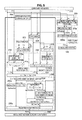
- FIG. 5 is a schematic diagram for explaining processes performed by the control apparatus
- FIG. 6 is a characteristic diagram illustrating a result of an FFT analysis of a steering wheel torque as frequency-related data related to steering
- FIG. 7 is a characteristic diagram illustrating a result of an FFT analysis of a steering wheel torque as frequency-related data related to steering
- FIG. 8 is a schematic diagram illustrating an example case where a ratio Sr between an area S1 represented by a waveform resulting from the frequency analysis and an area S2 represented by a portion of the waveform over a range greater than or equal to a predetermined frequency range (TH_FREQ) is used as the frequency-related data related to the steering;
- TH_FREQ predetermined frequency range
- FIG. 9 is a schematic diagram illustrating an example case where a ratio Sr between an area S1 represented by a waveform resulting from the frequency analysis and an area S2 represented by a portion of the waveform over a range greater than or equal to a predetermined frequency range (TH_FREQ) is used as the frequency-related data related to the steering;
- TH_FREQ predetermined frequency range
- FIG. 10 is a schematic diagram illustrating a map that is used when a steering correction gain calculator calculates a steering correction gain (SteerGain);
- FIG. 11 is a schematic diagram illustrating a gain map used when a feedback yaw rate computer calculates a weighting gain ⁇ ;
- FIG. 12 is a characteristic diagram illustrating a map for correcting a target stability factor SfTgt
- FIG. 13 is a characteristic diagram illustrating a map for calculating an inertia compensation yaw moment correction gain GainMgTrans;
- FIG. 14 is a schematic diagram for explaining control amounts and vehicle behaviors when control according to an implementation of the present invention is performed.
- FIG. 15 is a schematic diagram for explaining control amounts and vehicle behaviors when control according to an implementation of the present invention is performed.
- FIG. 16 is a schematic diagram for explaining control amounts and vehicle behaviors when control according to an implementation of the present invention is performed.
- FIG. 17 is a schematic diagram for explaining control amounts and vehicle behaviors when control according to an implementation of the present invention is performed.
- FIG. 18 is a schematic diagram for explaining control amounts and vehicle behaviors when control according to an implementation of the present invention is performed.
- FIG. 19 is a schematic diagram for explaining control amounts and vehicle behaviors when control according to an implementation of the present invention is performed.
- FIG. 20 is a schematic diagram for explaining control amounts and vehicle behaviors when control according to an implementation of the present invention is performed.
- FIG. 21 is a schematic diagram for explaining control amounts and vehicle behaviors when control according to an implementation of the present invention is performed.
- FIG. 22 is a schematic diagram for explaining control amounts and vehicle behaviors when control according to an implementation of the present invention is performed.
- FIG. 23 is a schematic diagram for explaining control amounts and vehicle behaviors when control according to an implementation of the present invention is performed.
- FIG. 24 is a schematic diagram for explaining control amounts and vehicle behaviors when control according to an implementation of the present invention is performed.
- FIG. 25 is a schematic diagram for explaining control amounts and vehicle behaviors when control according to an implementation of the present invention is performed.
- FIG. 26 is a schematic diagram for explaining control amounts and vehicle behaviors when control according to an implementation of the present invention is performed.
- FIG. 27 is a schematic diagram illustrating the steering wheel torque, the amount of motor control by a steering stability controller, a steering angle, and the amount of a turn of the vehicle with respect to each of an implementation of the present invention, comparative example 1, and comparative example 2 for comparison therebetween.
- FIG. 1 is a schematic diagram illustrating the vehicle 1000 according to the present implementation.
- the vehicle 1000 includes front wheels 100 and 102 ; rear wheels 104 and 106 ; driving force generators (i.e., motors) 108 , 110 , 112 , and 114 that drive the front wheels 100 and 102 and the rear wheels 104 and 106 , respectively; wheel speed sensors 116 , 118 , 120 , and 122 that measure the wheel speeds of the front wheels 100 and 102 and the rear wheels 104 and 106 , respectively; a steering wheel 124 ; a steering wheel angle sensor 130 ; a power steering mechanism 140 ; a yaw rate sensor 150 ; an acceleration sensor 160 ; outside recognizers 170 ; and a control apparatus (i.e., a controller) 200 .
- driving force generators i.e., motors
- wheel speed sensors 116 , 118 , 120 , and 122 that measure the wheel speeds of the front wheels 100 and 102 and the rear wheels 104
- the vehicle 1000 is equipped with the motors 108 , 110 , 112 , and 114 to drive the front wheels 100 and 102 and the rear wheels 104 and 106 , respectively.
- This allows a driving torque for each of the front wheels 100 and 102 and the rear wheels 104 and 106 to be controlled. Therefore, each of the front wheels 100 and 102 and the rear wheels 104 and 106 can be driven to generate a yaw rate through torque vectoring control independently of generation of a yaw rate by steering of the front wheels 100 and 102 .
- the torques applied to the rear wheels 104 and 106 are controlled individually to generate a yaw rate independently of a steering system.
- the motors 112 and 114 for the respective rear wheels 104 and 106 are controlled based on instructions from the control apparatus 200 to control the driving torques applied to the rear wheels 104 and 106 .
- the power steering mechanism 140 controls the steering angles of the front wheels 100 and 102 through torque control or angle control in accordance with an operation of the steering wheel 124 by a driver.
- the steering wheel angle sensor 130 measures a steering angle ⁇ h inputted by the driver operating the steering wheel 124 .
- the yaw rate sensor 150 measures an actual yaw rate ⁇ of the vehicle 1000 .
- the wheel speed sensors 116 , 118 , 120 , and 122 measure the vehicle speed V of the vehicle 1000 .
- the present invention is not limited to the above implementation, and that a vehicle according to another implementation of the present invention may be designed so that only the rear wheels 104 and 106 can generate driving forces independently with the motors 112 and 114 without the motors 108 and 102 that drive the front wheels 100 and 110 . Also note that the present invention is not limited to the torque vectoring control with driving force control, and that another implementation of the present invention may be applied to, for example, a four-wheel steering system in which the steering angles of the rear wheels are controlled.
- FIG. 2 is a schematic diagram illustrating turn control performed by the vehicle 1000 according to the present implementation, and is a schematic diagram illustrating turn control by steering (i.e., steering stability control).
- the tire steering angles of the front wheels 100 and 102 are varied in accordance with an operation of the steering wheel 124 by the driver, so that the vehicle 1000 makes a turn.
- a difference between the driving forces for the rear wheels 104 and 106 is caused to provide assistance in the turn of the vehicle 1000 .
- the vehicle 1000 is turning to the left in accordance with a steering by the driver (or an operator).
- a difference between the driving forces for the rear wheels 104 and 106 is caused to produce a forward driving force for the right rear wheel 106 , and cause a reduction in the driving force for the left rear wheel 104 compared to the driving force for the right rear wheel 106 , or produce a rearward driving force for the left rear wheel 104 .
- a difference between the driving forces for the left and right sides is thus caused to generate a yaw moment to provide assistance in the left turn.
- the amount of steering caused by steering control and a target stability factor used in control of the motor driving forces are adjusted based on a parameter related to the frequency of inputs, such as operations of the steering wheel, made by the driver into the vehicle 1000 , and thus, influence of a high-frequency component due to a road surface input or a hunting at the time of a turn is reduced to accomplish smooth steering while maintaining steering control through power steering and the amount of turn assist that accompanies vehicle braking/driving force control through the motors.
- a steering wheel torque and its frequency are calculated based on a steering model, and a control constant for the power steering and a control constant for motor control of the steering stability control are varied based on the steering wheel torque and its frequency. Details thereof will be described below.
- FIG. 3 is a schematic diagram illustrating the structure of the control apparatus 200 .
- the control apparatus 200 includes onboard sensors 210 , a power steering gain adjuster 205 , a steering stability controller 220 , and a required motor torque computer 280 .
- the power steering gain adjuster 205 includes a steering model 205 a , a frequency-related data calculator 205 b , a steering correction gain calculator 205 c , and a steering assist amount adjuster 205 d.
- the steering stability controller 220 includes a corrector 222 , a vehicle model 224 , a subtractor 228 , a control target yaw rate computer 230 , a feedback yaw rate computer (i.e., a feedback yaw rate acquirer) 232 , a subtractor 233 , and a control target yaw moment computer (i.e., a control target yaw moment calculator) 250 .
- the control target yaw rate computer 230 includes a tire steering angle converter 230 a and a ⁇ _Tgt computer 230 b .
- control target yaw moment computer 250 includes a damping control yaw moment computer 250 a , an inertia compensation yaw moment computer 250 b , and an adder 250 c .
- control target yaw rate computer 230 may serve as a “target yaw rate calculator”.
- feedback yaw rate computer 232 may serve as a “feedback yaw rate acquirer”.
- control target yaw moment computer 250 may serve as a “control target yaw moment calculator”.
- FIG. 4 is a flowchart illustrating a basic procedure performed in the present implementation.
- the power steering gain adjuster 205 adjusts a gain for the power steering.
- the corrector 222 corrects a target stability factor SfTgt.
- the control target yaw rate computer 230 calculates a control target yaw rate ⁇ _Tgt based on the target stability factor SfTgt.
- the feedback yaw rate computer 232 calculates a feedback yaw rate ⁇ F/B.
- control target yaw moment computer 250 calculates a control target yaw moment MgTgt based on a difference ⁇ _Tgt (i.e., an amount of yaw rate correction) between the control target yaw rate ⁇ _Tgt and the feedback yaw rate ⁇ F/B.
- ⁇ _Tgt i.e., an amount of yaw rate correction
- FIG. 5 is a schematic diagram for explaining processes performed by the control apparatus 200 .
- FIG. 5 illustrates the structural elements of the control apparatus 200 as does FIG. 3 , and additionally illustrates processes performed by the various structural elements in detail.
- the onboard sensors 210 include the steering wheel angle sensor 130 , the yaw rate sensor 150 , the acceleration sensor 160 , and the wheel speed sensors 116 , 118 , 120 , and 122 , all of which have been mentioned above.
- the power steering gain adjuster 205 adjusts the amount of assistance to be provided by the power steering mechanism 140 in accordance with a change in a state quantity related to ease of steering.
- state quantities related to the ease of steering include the steering wheel torque and the angular velocity of the steering wheel. If a high-frequency component is detected from the state quantity related to the ease of steering, it means that a hunting has occurred in the operation of the steering wheel, or that the operation of the steering wheel is shaky, for example. Accordingly, the amount of assistance in steering is varied in accordance with a change in data related to the frequency to reduce vibrations of the steering system that accompany steering wheel inputs and resulting vibrations of the vehicle.
- the steering model 205 a is a steering model that uses a steering wheel angle ⁇ h, a vehicle speed V, and a yaw rate ⁇ as inputs, and a reference value ( ⁇ Std) of a steering angle and the steering wheel torque (Trq) are calculated from the steering model 205 a.
- a steering wheel torque Th and a front wheel steering angle ⁇ resulting from an operation of the steering wheel by the driver are calculated in accordance with Eqs. (1) and (2) below.
- a steering wheel angle ⁇ is a value obtained by converting the steering wheel angle ⁇ h, which is measured by the steering wheel angle sensor 130 , to a value corresponding to a kingpin.
- Ih a yaw moment of inertia about a kingpin (corresponding to a yaw moment of inertia of the steering wheel)
- Ch a viscous friction coefficient of a steering shaft
- Ks an equivalent elastic modulus about the kingpin
- Th the steering wheel torque applied by the driver
- ⁇ the steering wheel angle (as converted to the value corresponding to the kingpin)
- ⁇ the front wheel steering angle (i.e., a tire steering angle)
- V the vehicle speed
- the front wheel steering angle ⁇ calculated from Eqs. (1) and (2) is used as the reference value ( ⁇ Std) of the steering angle.
- the frequency-related data calculator 205 b subjects the steering wheel torque calculated from the steering model 205 a to a frequency analysis, thus converting the steering wheel torque to frequency data.
- the steering wheel torque is subjected to an FFT analysis using a known method, and resulting data are calculated as frequency-related data (TrqFreqData) related to a steering input by the driver.
- the frequency-related data (TrqFreqData) related to the steering correspond to the state quantity related to the ease of steering, and the condition of the steering by the driver can be judged based on the frequency-related data (TrqFreqData).
- the frequency-related data (TrqFreqData) related to the steering are used as an indicator for varying a control constant for the power steering by the power steering gain adjuster 205 , and a control constant for the braking/driving force control by the steering stability controller 220 .
- FIGS. 6 and 7 are each a characteristic diagram illustrating a result of an FFT analysis of the steering wheel torque as the frequency-related data related to the steering.
- FIG. 6 represents a pattern in which high-frequency components have relatively low values and which represents a smooth steering.
- FIG. 7 represents a pattern in which high-frequency components have relatively high values and which represents a steering which is not smooth or a shaky steering.
- the frequency-related data (TrqFreqData) related to the steering have a greater value as the high-frequency components in the result of the FFT analysis of the steering wheel torque have higher values. Therefore, the frequency-related data (TrqFreqData) of the analysis result illustrated in FIG. 7 have a greater value than the frequency-related data (TrqFreqData) of the analysis result illustrated in FIG. 6 .
- FIGS. 8 and 9 each illustrates an example case where, not simply the frequency of the steering wheel torque alone is used as the frequency-related data related to the steering, but a ratio Sr between an area S1 represented by the waveform resulting from the frequency analysis and an area S2 represented by a portion of the waveform over a range greater than or equal to a predetermined frequency range (TH_FREQ) is used as the frequency-related data related to the steering in the example of FIGS. 6 and 7 .
- TH_FREQ predetermined frequency range
- the frequency-related data are calculated based on the ratio between the area S1 obtained by performing an integration of the waveform resulting from the frequency analysis and the area S2 obtained by performing an integration of the portion of the waveform over the range greater than or equal to the predetermined frequency range.
- the ratio Sr as illustrated in each of FIGS. 8 and 9 allows a determination whether higher-frequency components are great in proportion. Accordingly, the control constant for the power steering by the power steering gain adjuster 205 , and the control constant for the braking/driving force control by the steering stability controller 220 , may be varied in accordance with a change in the ratio Sr.
- another parameter may alternatively be used as the frequency-related data related to the steering.
- alternative parameters include a derivative of the steering wheel torque, a derivative of the steering wheel angle (i.e., the angular velocity of the steering wheel), and a result of a frequency analysis of the steering wheel angle.
- Other applicable examples of the frequency-related data related to the steering include a parameter obtained by subjecting a state quantity representing driver information to an FFT process, a parameter obtained by differentiating a state quantity representing driver information and monitoring the rate of change, a time at which a zero-crossing of a parameter representing driver information occurs, and a frequency calculated from this time. Further, a measurement of electrical activity of muscles of the driver may be used as the frequency-related data related to the steering.
- an actual steering wheel torque inputted by the driver and measured by a torque sensor may be used to perform feedback control in an implementation of the present invention, and in this case, a result of a frequency analysis of the actual steering wheel torque or a derivative of the actual steering wheel torque may be used as the frequency-related data related to the steering.
- the actual steering wheel torque may be measured by a torque sensor provided in the power steering mechanism 140 .
- a result of a frequency analysis of a difference between a torque calculated by the steering model 205 a and the actual steering wheel torque measured by the torque sensor, or a state quantity related to the frequency of the actual steering wheel torque may be used as an indicator to vary the control constant for the power steering and the control constant (i.e., an inertia compensation yaw moment correction gain GainMgTrans, which will be described below) for the braking/driving force control by the steering stability controller 220 .
- the control constant i.e., an inertia compensation yaw moment correction gain GainMgTrans, which will be described below
- Another indicator that represents driver information other than the steering wheel torque such as a result of a frequency analysis of the steering wheel angle or a steering speed, may be used, and the control constants may be varied based on such a parameter.
- a vehicle motion parameter may be used in combination as an indicator to vary the control constants.
- the control constants may be varied when an indicator that measures a turning condition of the vehicle 1000 , such as the yaw rate or a lateral acceleration of the vehicle 1000 , exceeds a predetermined threshold value in an implementation of the present invention.
- the control constants may be varied using a result of a frequency analysis of an indicator that represents driver information, such as the steering wheel torque or a measurement of the electrical activity of muscles of the driver obtained by measuring equipment, in an implementation of the present invention.
- the steering correction gain calculator 205 c performs a mapping process using the acquired frequency-related data (TrqFreqData) related to the steering as an input to calculate a steering correction gain (SteerGain).
- FIG. 10 is a schematic diagram illustrating a map that is used when the steering correction gain calculator 205 c calculates the steering correction gain (SteerGain).
- SteerGain MAX_GAIN
- SteerGain MIN_GAIN
- FIG. 10 along the vertical axis, SteerGain (MAX_GAIN) and SteerGain (MIN_GAIN) represent a steering correction gain (on a high-gain side) and a steering correction gain (on a low-gain side), respectively.
- TH_LOW_P and TH_LOW_M each represent a threshold value (on a low-frequency input side) for a change in the steering correction gain (SteerGain)
- TH_HIGH_P and TH_HIGH_M each represent a threshold value (on a high-frequency input side) for a change in the steering correction gain (SteerGain).
- the positive threshold values satisfy this relationship, TH_LOW_P ⁇ TH_HIGH_P
- the negative threshold values satisfy this relationship, TH_LOW_M>TH_HIGH_M.
- values of the steering correction gain (SteerGain) between TH_LOW_P and TH_HIGH_P and between TH_LOW_M and TH_HIGH_M are calculated through linear interpolation.
- the steering assist amount adjuster 205 d multiplies the reference value ( ⁇ Std) of the front wheel steering angle by the steering correction gain (SteerGain) based on Eq. (3) below to calculate a requested value ( ⁇ Req) of the front wheel steering angle in which the amount of assistance to be provided by the power steering has been corrected.
- the steering system (that is, the power steering mechanism 140 ) performs control of varying the front wheel steering angle, and varying the amount of assistance (e.g., the amount of steering or torque) to be provided by the power steering, based on the requested value ( ⁇ Req) of the front wheel steering angle.
- ⁇ Req SteerGain ⁇ Std (3)
- the steering correction gain (SteerGain) has an increased value, resulting in an increased requested value ( ⁇ Req) of the front wheel steering angle, and a turn of the vehicle is thus promoted.
- the steering correction gain (SteerGain) has a reduced value, resulting in a reduced requested value ( ⁇ Req) of the front wheel steering angle, and the degree of the turn of the vehicle is thus reduced. Accordingly, when the high-frequency components are great in proportion, the amount of steering of the front wheels is reduced, and the amount of assistance to be provided to the front wheel steering angle in accordance with the amount of a steering operation is adjusted.
- the power steering mechanism 140 reduces the change in the front wheel steering angle, and the amount of assistance (i.e., the amount of steering or torque) to be provided by the power steering mechanism 140 is reduced, resulting in increased stability of vehicle behavior.
- the value of the steering correction gain may be set to 1.
- control target yaw rate computer 230 calculates the control target yaw rate ⁇ _Tgt, which is used for the steering stability control, from Eq. (4) below, which represents a common two-dimensional two-wheel model.
- the control target yaw rate ⁇ _Tgt corresponds to a vehicle yaw rate ⁇ in Eq. (4), which represents the two-dimensional two-wheel model, and is calculated by substituting appropriate values into the right side of Eq. (4).
- V the vehicle speed
- ⁇ the tire steering angle (i.e., the front wheel steering angle)
- Gh a conversion gain in conversion from the steering wheel angle to the tire steering angle (i.e., the steering gear ratio)
- the control target yaw rate ⁇ _Tgt (i.e., ⁇ in the left side of Eq. (4)) is calculated from Eq. (4) with the vehicle speed V and the tire steering angle ⁇ as variables.
- the tire steering angle ⁇ in Eq. (4) cannot be obtained by direct sensing, and accordingly, the tire steering angle converter 230 a of the control target yaw rate computer 230 calculates the tire steering angle ⁇ by dividing the steering wheel angle ⁇ h by the conversion gain Gh based on Eq. (5). Note that the tire steering angle ⁇ may be calculated based on the aforementioned steering model.
- the steering gear ratio is used as the conversion gain Gh.
- the target stability factor SfTgt in Eq. (4) is generally calculated from Eq.
- the corrector 222 corrects the target stability factor SfTgt.
- the ⁇ _Tgt computer 230 b of the control target yaw rate computer 230 calculates the control target yaw rate ⁇ _Tgt from Eq. (4) using the tire steering angle ⁇ calculated by the tire steering angle converter 230 a .
- the control target yaw rate ⁇ _Tgt is inputted to the subtractor 233 .
- control target yaw rate ⁇ _Tgt which is used in the steering stability controller 220 , may be calculated based on environmental information acquired from the outside recognizer(s) 170 , which may be formed by a stereo camera or the like, or from an outside world recognizer, such as, for example, a navigation system. Also note that the control target yaw rate ⁇ _Tgt may be calculated based on a state quantity which is the sum of a weighted control target yaw rate calculated from at least one of the outside recognizer 170 and the outside world recognizer and a weighted control target yaw rate ⁇ _Tgt calculated based on the steering angle and the vehicle speed using Eq. (4).
- the vehicle model 224 determines the yaw rate of the vehicle 1000 through a calculation.
- the vehicle model 224 calculates a yaw rate model value ⁇ _clc based on the following equations which represent a vehicle model (i.e., a two-dimensional two-wheel model) for calculating the vehicle yaw rate. More specifically, the yaw rate model value ⁇ _clc (i.e., ⁇ in Eqs. (7) and (8) below) is calculated by substituting the vehicle speed V and the steering wheel angle ⁇ h into Eqs. (7) and (8) and solving Eqs. (7) and (8) simultaneously. Note that Eq. (4) can be derived from Eqs.
- the vehicle model 224 may calculate the yaw rate model value ⁇ _clc from Eq. (4), which represents the two-dimensional two-wheel model, by a method similar to the method employed by the control target yaw rate computer 230 , based on the steering wheel angle ⁇ h and the vehicle speed V.
- l denotes a yaw moment of inertia of the vehicle
- ⁇ denotes the side slip angle of the vehicle.
- the yaw rate model value ⁇ _clc is inputted to the feedback yaw rate computer 232 .
- the actual yaw rate ⁇ which is measured by the yaw rate sensor 150 , is inputted to the feedback yaw rate computer 232 .
- the subtractor 228 subtracts the actual yaw rate ⁇ from the yaw rate model value ⁇ _clc to calculate a difference ⁇ _diff between the yaw rate model value ⁇ _clc and the actual yaw rate ⁇ .
- the difference ⁇ _diff is inputted to the feedback yaw rate computer 232 .
- the difference ⁇ _diff corresponds to a parameter indicating the condition of a road surface, and the subtractor 228 therefore corresponds to a structural element that acquires a parameter indicating the condition of the road surface.
- the yaw rate model value ⁇ _clc, the actual yaw rate ⁇ , and the difference ⁇ _diff are inputted to the feedback yaw rate computer 232 .
- the feedback yaw rate computer 232 calculates a weighting gain ⁇ , which varies in accordance with the difference ⁇ _diff between the yaw rate model value ⁇ _clc and the actual yaw rate ⁇ , based on the difference ⁇ _diff.
- the feedback yaw rate computer 232 weights both the yaw rate model value ⁇ _clc and the actual yaw rate ⁇ using the weighting gain ⁇ , and calculates the feedback yaw rate ⁇ F/B based on Eq. (9) below.
- the calculated feedback yaw rate ⁇ F/B is inputted to the subtractor 233 .
- ⁇ F/B ⁇ _ clc +(1 ⁇ ) ⁇ (9)
- FIG. 11 is a schematic diagram illustrating a gain map used when the feedback yaw rate computer 232 calculates the weighting gain ⁇ .
- the value of the weighting gain ⁇ varies between 0 and 1 in accordance with the reliability of the vehicle model 224 .
- the difference (or deviation) ⁇ _diff between the yaw rate model value ⁇ _clc and the actual yaw rate ⁇ _sens is used as an indicator of the reliability of the vehicle model 224 .
- the gain map is set such that the value of the weighting gain ⁇ will be greater for smaller absolute values of the difference ⁇ _diff.
- the feedback yaw rate computer 232 subjects the difference ⁇ _diff to ⁇ mapping process of FIG. 11 to compute the weighting gain ⁇ in accordance with the reliability of the vehicle model.
- TH1_P represents a threshold value (on the positive side) for a change in the weighting gain ⁇
- TH2_P represents a threshold value (on the positive side) for a change in the weighting gain ⁇
- TH1_M represents a threshold value (on the negative side) for a change in the weighting gain ⁇
- TH2_M represents a threshold value (on the negative side) for a change in the weighting gain ⁇ .
- a region A1 in the gain map illustrated in FIG. 11 which is a region where the difference ⁇ _diff approaches 0, corresponds to a region where, for example, the S/N ratio is low, or a region where tire characteristics exhibit linearity (e.g., when the road surface is dry). Therefore, in the region A1, the yaw rate model value ⁇ _clc calculated by the vehicle model 216 has a high degree of reliability. Accordingly, the value of the weighting gain ⁇ is determined to be 1, and the feedback yaw rate ⁇ F/B is computed using Eq. (9) with a 100% distribution of the yaw rate model value ⁇ _clc.
- drive assist control provides predictive control of the amount of a turn of the vehicle 1000 based on a future course predicted from the condition of the vehicle 1000 traveling straight ahead before entering a corner. Accordingly, not only when the vehicle 1000 makes a turn but also when the vehicle 1000 is traveling straight ahead, the effect of sensor noise is excluded to prevent vibrations of the vehicle 1000 , and the vehicle 1000 is thus allowed to travel straight ahead with stability.
- a region where the yaw rate model value ⁇ _clc has a high degree of reliability can be specified based on the difference ⁇ _diff and the driving condition.
- an example coefficient setting using a map, and example correspondences between the difference ⁇ _diff and the weighting gain ⁇ used in the coefficient setting are such that the value of the weighting gain ⁇ is set to 1 when the vehicle is traveling on a dry road surface (i.e., a high ⁇ road surface) and the amount of steering is small (e.g., when the vehicle is making a slight turn).
- the aforementioned two-dimensional two-wheel model assumes a region where the relationship (i.e., the cornering characteristics of the tires) between the lateral accelerations and slip angles of the tires exhibits linearity.
- the yaw rate and the lateral acceleration of the actual vehicle vary nonlinearly with the steering angle, and a significant difference occurs between the yaw rate measured on the actual vehicle and the yaw rate of the two-dimensional two-wheel model.
- the reliability of the yaw rate model value ⁇ _clc can be easily determined based on the difference ⁇ _diff in the present implementation.
- a region A2 in the gain map illustrated in FIG. 11 which corresponds to, for example, a region where the difference ⁇ _diff has a large value, corresponds to, for example, a time when the vehicle is traveling on a wet road surface, a time when the vehicle is traveling on a snow-covered road, or a time when the vehicle is making a sharp turn, and is a marginal region in which the tires are sliding.
- the yaw rate model value ⁇ _clc calculated by the vehicle model 216 has a low degree of reliability, and the difference ⁇ _diff has a greater value.
- the value of the weighting gain ⁇ is determined to be 0, and the feedback yaw rate ⁇ F/B is computed using Eq. (9) with a 100% distribution of the actual yaw rate ⁇ .
- This contributes to ensuring sufficient precision of the feedback based on the actual yaw rate ⁇ , allowing feedback control of the yaw rate reflecting the behavior of the actual vehicle.
- a turn of the vehicle 1000 can thus be optimally controlled based on the actual yaw rate ⁇ .
- noise in a signal obtained by the yaw rate sensor 150 would not cause a vibration of the vehicle 1000 that can be perceived by the driver, and would not cause a significant reduction in ride comfort.
- the low ⁇ region A2 illustrated in FIG. 11 for which the value of the weighting gain ⁇ is determined to be 0, may be set based on design requirements, or may be experimentally determined based on steering stability performance, ride comfort, and so on when the vehicle 1000 actually travels on a low ⁇ road surface.
- a region A3 in the gain map illustrated in FIG. 11 which is a transitional region (a nonlinear region) from the linear region to the marginal region
- the distributions of the yaw rate model value ⁇ _clc and the actual yaw rate ⁇ are linearly varied while taking into account the tire characteristics of the actual vehicle 1000 as necessary.
- the weighting gain ⁇ is computed using linear interpolation to avoid a torque change and a yaw rate change caused by an abrupt change in the weighting gain ⁇ .
- a region A4 in the gain map illustrated in FIG. 11 corresponds to a case where the actual yaw rate ⁇ is greater than the yaw rate model value ⁇ _clc.
- the actual yaw rate ⁇ can be used based on a map of the region A4 to perform control.
- the actual yaw rate ⁇ can be used based on the map of the region A4 to perform control in the case where the yaw rate model value ⁇ _clc temporarily has a smaller value than that of the actual yaw rate ⁇ due to a phase delay in the actual yaw rate ⁇ that accompanies a filtering process.
- the range of the weighting gain ⁇ is not limited to the range of 0 to 1, and that any range of the weighting gain ⁇ that allows vehicle control may be adopted in other implementations of the present invention without departing from the scope of the present invention.
- the corrector 222 corrects the target stability factor SfTgt when the control target yaw rate computer 230 calculates the control target yaw rate ⁇ _Tgt from Eqs. (4) to (6).
- FIG. 12 is a characteristic diagram illustrating a map for correcting the target stability factor SfTgt. As illustrated in FIG. 12 , the target stability factor SfTgt, which is a parameter related to the turning performance of the vehicle, is corrected based on the frequency-related data (TrqFreqData) related to the steering.
- TrqFreqData frequency-related data
- Sf1 represents a stability factor that emphasizes responsive steering to promote a rotation (i.e., yawing) of the vehicle 1000
- Sf2 represents a stability factor that emphasizes stability to ensure sufficient stability performance at the time of a turn by controlling an excessive rotation (i.e., yawing) of the vehicle 1000
- TH1_P, TH2_P, TH3_P, TH4_P, TH1_M, TH2_M, TH3_M, and TH4_M each represent a threshold value for a change in the gain map
- P and M represent the positive and negative sides, respectively.
- values of the target stability factor SfTgt between TH1_P and TH2_P, between TH3_P and TH4_P, between TH1_M and TH2_M, and between TH3_M and TH4_M are calculated through linear interpolation. Accordingly, when the frequency-related data (TrqFreqData) related to the steering have a value between TH1_P and TH2_P, between TH3_P and TH4_P, between TH1_M and TH2_M, or between TH3_M and TH4_M, the value of SfTgt is calculated with distributions of Sf1 and Sf2 in accordance with the degree of divergence from each threshold value.
- the corrector 222 corrects the value of the target stability factor SfTgt in accordance with the change in the frequency-related data (TrqFreqData) related to the steering, which are calculated from an indicator related to the ease of steering, to increase or reduce an output of the braking/driving force control by the steering stability controller 220 . This compensates for an increase or reduction in the amount of assistance caused in accordance with the requested value ( ⁇ Req) of the front wheel tire steering angle by the power steering gain adjuster 205 .
- the value of the target stability factor SfTgt is shifted toward Sf1 (on an OS side), which emphasizes responsive steering, based on the frequency-related data (TrqFreqData) related to the steering.
- This increases the value of the control target yaw rate ⁇ _Tgt, which is calculated from Eq. (4), and thus increases a target value of the braking/driving force control by the steering stability controller 220 .
- the frequency-related data (TrqFreqData) have a large absolute value
- the requested value ( ⁇ Req) of the front wheel tire steering angle is made lower than the reference value ( ⁇ Std) in accordance with the map of FIG. 10 , but the value of the control target yaw rate ⁇ _Tgt is increased, and thus, a reduction in the amount of assistance (i.e., the amount of steering or torque) to be provided by the power steering can be compensated for through simultaneous performance of the steering control by the power steering and the braking/driving force control by the steering stability controller 220 .
- the value of the target stability factor SfTgt is shifted toward Sf2 (on a US side), which emphasizes the stability, based on the frequency-related data (TrqFreqData) related to the steering.
- the steering control by the power steering and the braking/driving force control by the steering stability controller 220 are simultaneously controlled so as to decrease the requested value ( ⁇ Req) of the front wheel tire steering angle in accordance with the map of FIG. 10 , and also to decrease the value of the control target yaw rate ⁇ _Tgt, in order to prevent an excessive turn of the vehicle.
- the target stability factor SfTgt is corrected based on the frequency-related data (TrqFreqData) related to the steering, so that when the steering is being performed with a low frequency, the control target yaw rate ⁇ _Tgt is calculated to have a value corresponding to a normal amount of a turn, while when the steering is being performed with a high frequency, the control target yaw rate ⁇ _Tgt is calculated to have a value greater than or equal to the value corresponding to the normal amount of the turn to promote the turn of the vehicle.
- the target stability factor SfTgt is thus corrected based on the frequency-related data to compute an optimum value of the control target yaw rate ⁇ _Tgt in accordance with the condition of the steering.
- the target stability factor SfTgt in Eq. (4) is a value that is determined in accordance with the specifications of the vehicle 1000 as is apparent from Eq. (6), and is a parameter that physically represents steering stability characteristics of the vehicle 1000 . Therefore, when the control target yaw rate ⁇ _Tgt is controlled, the target stability factor SfTgt is corrected and is thus controlled to accomplish a more natural behavior of the vehicle and a smooth turn of the vehicle.
- the value of the target stability factor SfTgt is shifted toward Sf2.
- the control amount of the driving force control by the steering stability controller 220 may become excessively large, and the value of the target stability factor SfTgt may thus be shifted toward Sf2 to prevent an excessive turn of the vehicle 1000 .
- the control target yaw rate ⁇ _Tgt is inputted from the control target yaw rate computer 230
- the feedback yaw rate ⁇ F/B is inputted from the feedback yaw rate computer 232 .
- the subtractor 233 subtracts the feedback yaw rate ⁇ F/B from the control target yaw rate ⁇ _Tgt to calculate a difference ⁇ _Tgt (i.e., the amount of yaw rate correction) between ⁇ _Tgt and ⁇ F/B. That is, the difference ⁇ _Tgt is calculated from Eq. (10) below.
- ⁇ _Tgt ⁇ _Tgt ⁇ F/B (10)
- the difference ⁇ _Tgt is outputted to the control target yaw moment computer 250 .
- the control target yaw moment computer 250 calculates a yaw moment to correct the vehicle behavior based on the difference ⁇ _Tgt.
- the control target yaw moment computer 250 calculates the control target yaw moment using the difference ⁇ _Tgt, and corrects the control target yaw moment using an adjustment gain to combine ensuring of stability when the steering wheel is being operated with a low frequency and turn assist control when the steering wheel is being operated with a high frequency, and controls the steering stability performance from the standpoint of both transient behavior and steady-state behavior at the time of a turn of the vehicle.
- control target yaw moment computer 250 includes the damping control yaw moment computer (i.e., a steady-state term calculator) 250 a , which calculates a “target damping yaw moment MgDampTgt”, which is a parameter for a convergence of the yaw rate of the vehicle 1000 , and the inertia compensation yaw moment computer (i.e., a transient term computer) 250 b , which calculates a “target inertia compensation yaw moment MgTransTgt”, which is a parameter for correcting the yaw moment of inertia of the vehicle 1000 .
- damping control yaw moment computer i.e., a steady-state term calculator
- MgDampTgt a parameter for a convergence of the yaw rate of the vehicle 1000
- inertia compensation yaw moment computer i.e., a transient term computer
- the damping control yaw moment computer i.e., the steady-state term calculator 250 a multiplies ⁇ _Tgt by a coefficient D1 (i.e., a damping yaw moment computation coefficient) to compute the “target damping yaw moment MgDampTgt” to improve convergence performance at the time of the turn of the vehicle.
- the coefficient D1 is a coefficient by which the yaw rate is multiplied in Eq. (11) below, in which a well-known two-dimensional two-wheel model (yawing) is arranged with respect to the yaw moment.
- the target damping yaw moment MgDampTgt corresponds to a basic amount of a damping yaw moment used in the driving force control.
- the coefficient D1 corresponds to 2/V(lf2Kf+lr2Kr), by which ⁇ is multiplied in Eq. (11).
- the “target damping yaw moment MgDampTgt” serves to stabilize the vehicle behavior with respect to, in particular, the steady-state behavior of the vehicle 1000 .
- the inertia compensation yaw moment computer (i.e., the transient term computer) 250 b multiplies a derivative of ⁇ _Tgt by a coefficient T1 (i.e., an inertia compensation yaw moment computation coefficient) to compute a basic amount MgTransBasis of the “target inertia compensation yaw moment MgTransTgt” to correct the yaw moment of inertia at the time of the turn of the vehicle.
- the coefficient T1 is a coefficient by which a yaw acceleration is multiplied in Eq. (11), in which the well-known two-dimensional two-wheel model (yawing) is arranged with respect to the yaw moment.
- the basic amount MgTransBasis is calculated from Eq. (13) below.
- the basic amount MgTransBasis corresponds to a basic amount of an inertia compensation yaw moment used in the driving force control.
- the coefficient T1 corresponds to l (i.e., the yaw moment of inertia of the vehicle), by which d ⁇ /dt is multiplied in Eq. (11).
- the inertia compensation yaw moment computer i.e., the transient term computer
- the inertia compensation yaw moment computer 250 b corrects the basic amount MgTransBasis by multiplying the basic amount MgTransBasis of the “target inertia compensation yaw moment MgTransTgt” by a gain that is set in accordance with the frequency-related data (TrqFreqData) related to the steering to calculate the “target inertia compensation yaw moment MgTransTgt”.
- the “target inertia compensation yaw moment MgTransTgt” serves to stabilize the vehicle behavior with respect to, in particular, momentary behavior of the vehicle 1000 .
- MgTransBasis T ⁇ ⁇ 1 ⁇ d ⁇ d ⁇ ⁇ t ⁇ ( ⁇ _Tgt ) ( 13 )
- the inertia compensation yaw moment computer 250 b has a function of calculating the gain GainMgTrans for correcting the inertia compensation yaw moment, and of varying the gain GainMgTrans in accordance with the frequency-related data (TrqFreqData) related to the steering.
- the inertia compensation yaw moment computer 250 b determines the degree of stability of the vehicle behavior with respect to the steering, and calculates the correction gain GainMgTrans, which has a function of limiting an output of the inertia compensation yaw moment when the steering wheel is being operated with a high frequency.
- the gain is reduced to a negative value, and a transient inverse yaw moment is added to ensure sufficient stability performance of the vehicle 1000 .
- a transient inverse yaw moment is not added to avoid an excessive reduction in the turning performance, and control is performed to maintain sufficient turning performance of the vehicle 1000 even in a high-frequency region.
- the inertia compensation yaw moment computer 250 b calculates the gain GainMgTrans for correcting the basic amount MgTransBasis of the target inertia compensation yaw moment MgTransTgt in accordance with the value of the frequency-related data (TrqFreqData) related to the steering.
- TrqFreqData frequency-related data
- responsivity of the vehicle 1000 is emphasized when low-frequency inputs are predominant, such as when a gentle steering is being performed, while when high-frequency inputs are predominant, such as when the steering is shaky, an inverse yaw moment is added to ensure sufficient stability performance of the vehicle.
- convergence performance of the control for, in particular, high-frequency steering inputs can be improved.
- the inertia compensation yaw moment computer 250 b first multiplies the derivative of ⁇ _Tgt by the coefficient T1 to calculate the basic amount MgTransBasis.
- the inertia compensation yaw moment computer 250 b then multiplies the calculated basic amount MgTransBasis by the inertia compensation yaw moment correction gain GainMgTrans, which varies in accordance with the frequency-related data (TrqFreqData) related to the steering, to calculate the target inertia compensation yaw moment MgTransTgt.
- FIG. 13 is a characteristic diagram illustrating a map for calculating the inertia compensation yaw moment correction gain GainMgTrans.
- TH1_P, TH2_P, TH3_P, TH4_P, TH5_P, TH6_P, TH1_M, TH2_M, TH3_M, TH4_M, TH5_M, and TH6_M each represent a threshold value for a change in the gain map
- P and M represent the positive and negative sides, respectively.
- the inertia compensation yaw moment correction gain GainMgTrans comes to have a negative value, which reduces the value of the control target yaw moment MgTgt, which is the sum of the target damping yaw moment MgDampTgt and the target inertia compensation yaw moment MgTransTgt. This leads to a value of the control target yaw moment MgTgt that serves to prevent an excessive turn of the vehicle.
- the value of the frequency-related data (TrqFreqData) related to the steering becomes greater than TH3_P, and it is determined that a higher-frequency steering input has been made or that the marginal region has been reached, the value of the inertia compensation yaw moment correction gain GainMgTrans is made closer to 0 (neutral) without adding an inverse yaw moment.
- map of FIG. 13 is merely an example, and that any value that allows control of the vehicle, including 0 and negative values, can be set as a value of the inertia compensation yaw moment correction gain GainMgTrans.
- the vehicle behavior can be stabilized by reducing the hunting or the shaky steering by reducing a transient motion of the vehicle 1000 . Accordingly, an inverse yaw moment is added with a negative value of the inertia compensation yaw moment correction gain GainMgTrans to reduce the transient motion of the vehicle to stabilize the vehicle behavior.
- a transient term i.e., the target inertia compensation yaw moment MgTransTgt
- a steady-state term e.g., the target damping yaw moment MgDampTgt
- the target damping yaw moment MgDampTgt may be corrected to correct steady-state turning performance of the vehicle 1000 for relatively gentle turns.
- the adder 250 c in the control target yaw moment computer 250 adds up the target damping yaw moment MgDampTgt and the target inertia compensation yaw moment MgTransTgt to calculate the control target yaw moment MgTgt to be used in the steering stability control. That is, the control target yaw moment MgTgt is calculated from Eq. (14) below.
- Mg Tgt Mg DampTgt+ Mg TransTgt (14)
- the control target yaw moment MgTgt calculated by the control target yaw moment computer 250 is inputted to the required motor torque computer 280 .
- the required motor torque computer 280 calculates the required motor torque based on the control target yaw moment MgTgt.
- a solid line represents a characteristic (the present implementation) in the case where both the control by the power steering gain adjuster 205 and the control by the steering stability controller 220 according to the present implementation are performed.
- a broken line represents a characteristic (comparative example 2) in the case where only the control by the power steering gain adjuster 205 is performed.
- a dot-dashed line represents a characteristic (comparative example 1) in the case where the corrections of the control amounts are not performed either in the control by the power steering gain adjuster 205 or the control by the steering stability controller 220 .
- FIG. 27 is a schematic diagram illustrating the steering wheel torque, the amount of motor control by the steering stability controller, the steering angle, and the amount of a turn of the vehicle with respect to each of the present implementation, comparative example 1, and comparative example 2 for comparison therebetween.
- both the steering wheel torque and the steering angle are reduced by the control by the power steering gain adjuster 205 when, in particular, a high-frequency operation of the steering wheel is being performed.
- the control amount by the control by the steering stability controller 220 is increased.
- the control by only the power steering gain adjuster 205 i.e., a reduction in output in response to a high-frequency input
- the amount of the turn of the vehicle 1000 is reduced compared to the steering by the driver.
- both the control by the power steering gain adjuster 205 and the control by the steering stability controller 220 are performed, and the amount of the turn of the vehicle 1000 is accordingly maintained for the steering by the driver of the vehicle 1000 .
- FIG. 15 illustrates the value of the frequency-related data (TrqFreqData) related to the steering.
- the steering wheel is operated in a smooth manner in the region A, and the operation of the steering wheel is shaky (or irregular) in the regions B and C.
- the frequency-related data (TrqFreqData) related to the steering have a constant value (here, a value of “1” as an example), and the amount of assistance to be provided by the power steering mechanism 140 is not increased, and normal control is performed, in each of the three characteristics.
- the operation of the steering wheel is shaky (or irregular) in the regions B and C.
- the amount of the steering operation is corrected, and the frequency-related data (TrqFreqData) related to the steering have a value less than or equal to 1 in each of the characteristics represented by the solid line (the present implementation) and the broken line.
- the frequency-related data (TrqFreqData) related to the steering have a constant value of “1” because the control by the power steering gain adjuster 205 is not performed.
- FIG. 16 illustrates the requested value ( ⁇ Req) of the front wheel steering angle.
- the frequency-related data TrqFreqData
- the frequency-related data TrqFreqData
- the requested value ( ⁇ Req) of the front wheel steering angle is reduced in accordance with the value of the frequency-related data (TrqFreqData) related to the steering in each of the characteristics represented by the solid line and the broken line when compared to the case of the characteristic represented by the dot-dashed line.
- the steering of the front wheels can thus be reduced when the steering is shaky.
- FIG. 17 illustrates the target stability factor SfTgt.
- the target stability factor SfTgt In the situation corresponding to the region A in FIG. 14 and in which the operation of the steering wheel is smooth, the target stability factor SfTgt is not corrected, and normal control is performed, in the characteristic represented by the solid line.
- the target stability factor SfTgt In addition, in each of the characteristics represented by the broken line and the dot-dashed line, the target stability factor SfTgt is not corrected, maintaining a constant value, and normal control is accordingly performed.
- the target stability factor SfTgt is corrected in the characteristic represented by the solid line.
- the target stability factor SfTgt maintains a constant value in each of the characteristics represented by the broken line and the dot-dashed line.
- FIG. 18 illustrates the control target yaw rate ⁇ _Tgt.
- the target stability factor SfTgt has the same value in each of the characteristics represented by the solid line, the broken line, and the dot-dashed line, and the control target yaw rate ⁇ _Tgt accordingly has the same value, and normal control is performed, in each of the characteristics.
- the target stability factor SfTgt is corrected, and the absolute value of the control target yaw rate ⁇ _Tgt is accordingly increased, in the characteristic represented by the solid line.
- the target stability factor SfTgt maintains the constant value. It is therefore apparent that the absolute value of the control target yaw rate ⁇ _Tgt is increased to promote a turn of the vehicle in the characteristic represented by the solid line when compared to the cases of the characteristics represented by the broken line and the dot-dashed line.
- FIG. 19 illustrates the inertia compensation yaw moment correction gain GainMgTrans.
- the gain GainMgTrans is not corrected in the characteristic represented by the solid line.
- the gain GainMgTrans always maintains a constant value. Therefore, the gain GainMgTrans has the same value in each of the characteristics represented by the solid line, the broken line, and the dot-dashed line. Meanwhile, in the situations corresponding to the regions B and C in FIG.
- the gain GainMgTrans is corrected, and the value thereof is reduced even to a negative value, in the characteristic represented by the solid line, while the value of the gain GainMgTrans is not corrected in each of the characteristics represented by the broken line and the dot-dashed line.
- FIG. 20 illustrates the target inertia compensation yaw moment MgTransTgt.
- the gain GainMgTrans is not corrected in the characteristic represented by the solid line. Therefore, in each of the characteristics represented by the solid line, the broken line, and the dot-dashed line, normal control is performed, and the value of the target inertia compensation yaw moment MgTransTgt is substantially the same. Meanwhile, in the situations corresponding to the regions B and C in FIG.
- the gain GainMgTrans is gradually varied from positive values to negative values in accordance with the inputs, and a transient control yaw moment is reduced, or a transient inverse yaw moment is added, to reduce the absolute value of the target inertia compensation yaw moment MgTransTgt, when compared to the characteristics represented by the broken line and the dot-dashed line. Sufficient stability performance of the vehicle 1000 can thus be ensured.
- FIG. 21 illustrates the control target yaw moment MgTgt.
- the inertia compensation yaw moment correction gain GainMgTrans is not corrected in the characteristic represented by the solid line. Therefore, in each of the characteristics represented by the solid line, the broken line, and the dot-dashed line, normal control is performed, and the value of the control target yaw moment MgTgt is substantially the same. Meanwhile, in the situations corresponding to the regions B and C in FIG.
- a transient inverse yaw moment is added to reduce the absolute value of the control target yaw moment MgTgt when compared to the characteristics represented by the broken line and the dot-dashed line. Sufficient stability performance of the vehicle 1000 can thus be ensured.
- FIG. 22 illustrates the actual yaw rate of the vehicle 1000 .
- the actual yaw rate has substantially the same value in each of the characteristics represented by the solid line, the broken line, and the dot-dashed line.
- FIG. 23 illustrates the lateral acceleration (Gy) of the vehicle 1000 .
- the lateral acceleration has equivalent values in each of the characteristics represented by the solid line, the broken line, and the dot-dashed line.
- the lateral acceleration has equivalent values in each of the characteristics represented by the solid line, the broken line, and the dot-dashed line.
- FIG. 24 illustrates the amount of lateral movement of the vehicle 1000 .
- the amount of lateral movement has equivalent values in each of the characteristics represented by the solid line, the broken line, and the dot-dashed line. Meanwhile, in the situations corresponding to the regions B and C in FIG.
- the amount of assistance provided by the power steering is reduced, so that a shaky steering may become easily avoidable, when compared to the case of the characteristic represented by the dot-dashed line, but the driving course of the vehicle 1000 for a given amount of the steering operation will change, and the absolute value of the amount of lateral movement is reduced, leading to an uncomfortable feeling of the driver.
- FIGS. 25 and 26 how the control amounts (i.e., the actual yaw rate ⁇ , the lateral acceleration Gy, and the amount of lateral movement) as illustrated in FIG. 26 vary when the steering wheel is operated in a manner as illustrated in FIG. 25 with a constant vehicle speed will be described.
- the same time domain is adopted along the horizontal axis.
- a solid line represents a characteristic in the case where both the control by the power steering gain adjuster 205 and the control by the steering stability controller 220 according to the present implementation are performed.
- a broken line represents a characteristic in the case where only the control by the power steering gain adjuster 205 is performed.
- a dot-dashed line represents a characteristic in the case where neither the control by the power steering gain adjuster 205 nor the control by the steering stability controller 220 is performed.
- each of the control amounts i.e., the actual yaw rate ⁇ , the lateral acceleration Gy, and the amount of lateral movement
Landscapes
- Engineering & Computer Science (AREA)
- Transportation (AREA)
- Mechanical Engineering (AREA)
- Chemical & Material Sciences (AREA)
- Combustion & Propulsion (AREA)
- Physics & Mathematics (AREA)
- Mathematical Physics (AREA)
- Steering Control In Accordance With Driving Conditions (AREA)
- Automation & Control Theory (AREA)
- Control Of Driving Devices And Active Controlling Of Vehicle (AREA)
Abstract
Description
δReq=SteerGain×δStd (3)
γF/B=κ×γ_clc+(1−κ)×γ (9)
Δγ_Tgt=γ_Tgt−γF/B (10)
MgDampTgt=D1×Δγ_Tgt (12)
MgTgt=MgDampTgt+MgTransTgt (14)
Claims (15)
Applications Claiming Priority (2)
| Application Number | Priority Date | Filing Date | Title |
|---|---|---|---|
| JP2015-167958 | 2015-08-27 | ||
| JP2015167958A JP6078124B1 (en) | 2015-08-27 | 2015-08-27 | Vehicle control apparatus and vehicle control method |
Publications (2)
| Publication Number | Publication Date |
|---|---|
| US20170057540A1 US20170057540A1 (en) | 2017-03-02 |
| US10144446B2 true US10144446B2 (en) | 2018-12-04 |
Family
ID=57981636
Family Applications (1)
| Application Number | Title | Priority Date | Filing Date |
|---|---|---|---|
| US15/238,432 Active US10144446B2 (en) | 2015-08-27 | 2016-08-16 | Vehicle and method for controlling vehicle |
Country Status (4)
| Country | Link |
|---|---|
| US (1) | US10144446B2 (en) |
| JP (1) | JP6078124B1 (en) |
| CN (1) | CN106476798B (en) |
| DE (1) | DE102016115662A1 (en) |
Cited By (1)
| Publication number | Priority date | Publication date | Assignee | Title |
|---|---|---|---|---|
| US11279375B2 (en) * | 2016-10-18 | 2022-03-22 | Audi Ag | Method for operating a motor vehicle having a plurality of driver assistance systems |
Families Citing this family (21)
| Publication number | Priority date | Publication date | Assignee | Title |
|---|---|---|---|---|
| KR102389093B1 (en) * | 2015-12-10 | 2022-04-21 | 주식회사 만도 | Steering control apparatus and steering control method |
| JP6573643B2 (en) * | 2017-03-27 | 2019-09-11 | 株式会社Subaru | Vehicle travel control device |
| JP2020100163A (en) * | 2017-04-07 | 2020-07-02 | ヤマハ発動機株式会社 | Handling input information acquisition system |
| JP7027738B2 (en) | 2017-09-06 | 2022-03-02 | 株式会社デンソー | Driving support device |
| JP6844500B2 (en) * | 2017-10-30 | 2021-03-17 | トヨタ自動車株式会社 | Vehicle behavior control device |
| US11110895B2 (en) * | 2018-04-09 | 2021-09-07 | Cisco Technology, Inc. | Vehicle network intrusion detection system (IDS) using vehicle state predictions |
| US11354406B2 (en) * | 2018-06-28 | 2022-06-07 | Intel Corporation | Physics-based approach for attack detection and localization in closed-loop controls for autonomous vehicles |
| JP7294814B2 (en) * | 2019-01-10 | 2023-06-20 | 株式会社ジェイテクト | Rudder control device |
| CN111483467B (en) * | 2019-01-29 | 2022-01-11 | 华为技术有限公司 | A vehicle control method and device |
| JP2020163890A (en) * | 2019-03-28 | 2020-10-08 | 株式会社アドヴィックス | Travel control device |
| DE102019206980B4 (en) * | 2019-05-14 | 2023-06-22 | Volkswagen Aktiengesellschaft | Method and steering control device for determining a manipulated variable for setting a power steering torque in a vehicle steering system |
| DE112020003777B4 (en) * | 2019-08-09 | 2025-06-26 | Nidec Corporation | Electric power steering device, control device used in an electric power steering device, and control method |
| FR3100780B1 (en) * | 2019-09-17 | 2021-09-24 | Renault Sas | Method for regulating the lateral position of a motor vehicle. |
| JP6810779B1 (en) * | 2019-09-26 | 2021-01-06 | 株式会社ショーワ | State quantity calculation device, control device and vehicle |
| JP6785997B1 (en) * | 2020-01-21 | 2020-11-18 | 株式会社ショーワ | Steering control device and steering device |
| CN111645755B (en) * | 2020-05-18 | 2021-10-01 | 长城汽车股份有限公司 | A control method and device |
| JP7247992B2 (en) * | 2020-08-28 | 2023-03-29 | トヨタ自動車株式会社 | vehicle controller |
| CN117836168B (en) * | 2021-08-30 | 2025-01-07 | 日产自动车株式会社 | Electric vehicle control method and electric vehicle control device |
| CN113619681B (en) * | 2021-09-15 | 2022-06-10 | 东风汽车集团股份有限公司 | Active stability control method and system for curve |
| CN117207952A (en) * | 2022-06-02 | 2023-12-12 | 本田技研工业株式会社 | Vehicle steering control device |
| EP4722079A1 (en) * | 2023-05-25 | 2026-04-08 | Mitsubishi Electric Mobility Corporation | Input/output device, method for manufacturing vehicle , and program |
Citations (7)
| Publication number | Priority date | Publication date | Assignee | Title |
|---|---|---|---|---|
| US20040193345A1 (en) * | 2003-03-28 | 2004-09-30 | Chen Hsien H. | Active steering for handling/stability enhancement |
| US20080114511A1 (en) * | 2005-05-18 | 2008-05-15 | Toyota Jidosha Kabushiki Kaisha | Running Control Apparatus For Vehicle |
| JP2009126186A (en) | 2007-11-19 | 2009-06-11 | Toyota Motor Corp | Electric power steering device |
| JP2012210832A (en) | 2011-03-30 | 2012-11-01 | Toyota Motor Corp | Driving force control device of vehicle |
| JP2013103664A (en) | 2011-11-15 | 2013-05-30 | Denso Corp | Electric power steering control device |
| JP2014141174A (en) | 2013-01-24 | 2014-08-07 | Mazda Motor Corp | Lane keeping assist device |
| JP2015003697A (en) | 2013-06-24 | 2015-01-08 | 三菱自動車工業株式会社 | Vehicle stabilizer |
-
2015
- 2015-08-27 JP JP2015167958A patent/JP6078124B1/en not_active Expired - Fee Related
-
2016
- 2016-08-16 US US15/238,432 patent/US10144446B2/en active Active
- 2016-08-23 CN CN201610703244.5A patent/CN106476798B/en not_active Expired - Fee Related
- 2016-08-24 DE DE102016115662.0A patent/DE102016115662A1/en not_active Withdrawn
Patent Citations (7)
| Publication number | Priority date | Publication date | Assignee | Title |
|---|---|---|---|---|
| US20040193345A1 (en) * | 2003-03-28 | 2004-09-30 | Chen Hsien H. | Active steering for handling/stability enhancement |
| US20080114511A1 (en) * | 2005-05-18 | 2008-05-15 | Toyota Jidosha Kabushiki Kaisha | Running Control Apparatus For Vehicle |
| JP2009126186A (en) | 2007-11-19 | 2009-06-11 | Toyota Motor Corp | Electric power steering device |
| JP2012210832A (en) | 2011-03-30 | 2012-11-01 | Toyota Motor Corp | Driving force control device of vehicle |
| JP2013103664A (en) | 2011-11-15 | 2013-05-30 | Denso Corp | Electric power steering control device |
| JP2014141174A (en) | 2013-01-24 | 2014-08-07 | Mazda Motor Corp | Lane keeping assist device |
| JP2015003697A (en) | 2013-06-24 | 2015-01-08 | 三菱自動車工業株式会社 | Vehicle stabilizer |
Non-Patent Citations (1)
| Title |
|---|
| Office Action received for Japanese Patent application No. 2015-167958, dated Oct. 4, 2016, 3 pages of office action including 2 pages of English translation. |
Cited By (1)
| Publication number | Priority date | Publication date | Assignee | Title |
|---|---|---|---|---|
| US11279375B2 (en) * | 2016-10-18 | 2022-03-22 | Audi Ag | Method for operating a motor vehicle having a plurality of driver assistance systems |
Also Published As
| Publication number | Publication date |
|---|---|
| CN106476798A (en) | 2017-03-08 |
| JP2017043246A (en) | 2017-03-02 |
| DE102016115662A1 (en) | 2017-03-02 |
| JP6078124B1 (en) | 2017-02-08 |
| US20170057540A1 (en) | 2017-03-02 |
| CN106476798B (en) | 2018-01-09 |
Similar Documents
| Publication | Publication Date | Title |
|---|---|---|
| US10144446B2 (en) | Vehicle and method for controlling vehicle | |
| US10272943B2 (en) | Control unit for vehicle and control method for vehicle | |
| CN103906672B (en) | Steering control device | |
| US10654470B2 (en) | Vehicle control apparatus and method for controlling vehicle | |
| US10144416B2 (en) | Apparatus and method for controlling vehicle | |
| US7680577B2 (en) | Estimating method for road friction coefficient and vehicle slip angle estimating method | |
| US6904349B2 (en) | Method of estimating quantities that represent state of vehicle | |
| US7092805B2 (en) | Steering apparatus for steerable vehicle | |
| CN103906671B (en) | Steering controlling device | |
| US6922617B2 (en) | Vehicle control device and vehicle control method | |
| US6560524B2 (en) | Integration of rear wheel steering with vehicle stability enhancement system | |
| RU2437793C2 (en) | Device for transport facility steering mechanism | |
| US9180880B2 (en) | Driving force control system for vehicle | |
| US10196057B2 (en) | Vehicle stability control device | |
| US20060095188A1 (en) | Ackerman angle correction in a steering system for a low speed turn | |
| JP6428497B2 (en) | Vehicle control device | |
| JP4636255B2 (en) | Wheel lateral force estimation device and steering reaction force control device | |
| JP2006056388A (en) | Estimation method of road friction coefficient |
Legal Events
| Date | Code | Title | Description |
|---|---|---|---|
| AS | Assignment |
Owner name: FUJI JUKOGYO KABUSHIKI KAISHA, JAPAN Free format text: ASSIGNMENT OF ASSIGNORS INTEREST;ASSIGNORS:ANMA, YOSHISADA;TORII, TAKESHI;SIGNING DATES FROM 20160518 TO 20160529;REEL/FRAME:039458/0522 |
|
| AS | Assignment |
Owner name: SUBARU CORPORATION, JAPAN Free format text: CHANGE OF NAME;ASSIGNOR:FUJI JUKOGYO KABUSHIKI KAISHA;REEL/FRAME:042624/0886 Effective date: 20170401 |
|
| STCF | Information on status: patent grant |
Free format text: PATENTED CASE |
|
| MAFP | Maintenance fee payment |
Free format text: PAYMENT OF MAINTENANCE FEE, 4TH YEAR, LARGE ENTITY (ORIGINAL EVENT CODE: M1551); ENTITY STATUS OF PATENT OWNER: LARGE ENTITY Year of fee payment: 4 |