US10138665B2 - Enclosure assembly with concealed hinge system - Google Patents
Enclosure assembly with concealed hinge system Download PDFInfo
- Publication number
- US10138665B2 US10138665B2 US15/514,250 US201615514250A US10138665B2 US 10138665 B2 US10138665 B2 US 10138665B2 US 201615514250 A US201615514250 A US 201615514250A US 10138665 B2 US10138665 B2 US 10138665B2
- Authority
- US
- United States
- Prior art keywords
- enclosure assembly
- cover
- hinge
- hinges
- footplate
- Prior art date
- Legal status (The legal status is an assumption and is not a legal conclusion. Google has not performed a legal analysis and makes no representation as to the accuracy of the status listed.)
- Active, expires
Links
Images


Classifications
-
- E—FIXED CONSTRUCTIONS
- E05—LOCKS; KEYS; WINDOW OR DOOR FITTINGS; SAFES
- E05D—HINGES OR SUSPENSION DEVICES FOR DOORS, WINDOWS OR WINGS
- E05D7/00—Hinges or pivots of special construction
- E05D7/08—Hinges or pivots of special construction for use in suspensions comprising two spigots placed at opposite edges of the wing, especially at the top and the bottom, e.g. trunnions
- E05D7/081—Hinges or pivots of special construction for use in suspensions comprising two spigots placed at opposite edges of the wing, especially at the top and the bottom, e.g. trunnions the pivot axis of the wing being situated near one edge of the wing, especially at the top and bottom, e.g. trunnions
-
- E—FIXED CONSTRUCTIONS
- E05—LOCKS; KEYS; WINDOW OR DOOR FITTINGS; SAFES
- E05D—HINGES OR SUSPENSION DEVICES FOR DOORS, WINDOWS OR WINGS
- E05D3/00—Hinges with pins
- E05D3/02—Hinges with pins with one pin
-
- E—FIXED CONSTRUCTIONS
- E05—LOCKS; KEYS; WINDOW OR DOOR FITTINGS; SAFES
- E05D—HINGES OR SUSPENSION DEVICES FOR DOORS, WINDOWS OR WINGS
- E05D5/00—Construction of single parts, e.g. the parts for attachment
- E05D5/02—Parts for attachment, e.g. flaps
- E05D5/06—Bent flaps
-
- E—FIXED CONSTRUCTIONS
- E05—LOCKS; KEYS; WINDOW OR DOOR FITTINGS; SAFES
- E05D—HINGES OR SUSPENSION DEVICES FOR DOORS, WINDOWS OR WINGS
- E05D7/00—Hinges or pivots of special construction
- E05D7/009—Elongate hinges, e.g. piano-hinges
-
- E—FIXED CONSTRUCTIONS
- E05—LOCKS; KEYS; WINDOW OR DOOR FITTINGS; SAFES
- E05D—HINGES OR SUSPENSION DEVICES FOR DOORS, WINDOWS OR WINGS
- E05D3/00—Hinges with pins
- E05D3/02—Hinges with pins with one pin
- E05D2003/025—Hinges with pins with one pin having three knuckles
-
- E—FIXED CONSTRUCTIONS
- E05—LOCKS; KEYS; WINDOW OR DOOR FITTINGS; SAFES
- E05Y—INDEXING SCHEME RELATING TO HINGES OR OTHER SUSPENSION DEVICES FOR DOORS, WINDOWS OR WINGS AND DEVICES FOR MOVING WINGS INTO OPEN OR CLOSED POSITION, CHECKS FOR WINGS AND WING FITTINGS NOT OTHERWISE PROVIDED FOR, CONCERNED WITH THE FUNCTIONING OF THE WING
- E05Y2600/00—Mounting or coupling arrangements for elements provided for in this subclass
- E05Y2600/40—Mounting location; Visibility of the elements
- E05Y2600/41—Concealed
-
- E—FIXED CONSTRUCTIONS
- E05—LOCKS; KEYS; WINDOW OR DOOR FITTINGS; SAFES
- E05Y—INDEXING SCHEME RELATING TO HINGES OR OTHER SUSPENSION DEVICES FOR DOORS, WINDOWS OR WINGS AND DEVICES FOR MOVING WINGS INTO OPEN OR CLOSED POSITION, CHECKS FOR WINGS AND WING FITTINGS NOT OTHERWISE PROVIDED FOR, CONCERNED WITH THE FUNCTIONING OF THE WING
- E05Y2900/00—Application of doors, windows, wings or fittings thereof
- E05Y2900/20—Application of doors, windows, wings or fittings thereof for furnitures, e.g. cabinets
-
- E—FIXED CONSTRUCTIONS
- E05—LOCKS; KEYS; WINDOW OR DOOR FITTINGS; SAFES
- E05Y—INDEXING SCHEME RELATING TO HINGES OR OTHER SUSPENSION DEVICES FOR DOORS, WINDOWS OR WINGS AND DEVICES FOR MOVING WINGS INTO OPEN OR CLOSED POSITION, CHECKS FOR WINGS AND WING FITTINGS NOT OTHERWISE PROVIDED FOR, CONCERNED WITH THE FUNCTIONING OF THE WING
- E05Y2900/00—Application of doors, windows, wings or fittings thereof
- E05Y2900/60—Application of doors, windows, wings or fittings thereof for other use
- E05Y2900/602—Application of doors, windows, wings or fittings thereof for other use for containers
Definitions
- the present disclosure relates to the field of mechanical engineering.
- the present disclosure relates to an enclosure assembly with concealed hinge system.
- the conventional enclosure assemblies for electrical systems comprise a cabinet and a cover that is functionally coupled with the cabinet.
- the cabinet can be made from a metallic material like steel or aluminium, or a non-metallic material like fiber glass or composite glass.
- the cabinet has a box-like configuration and is open at one end, which is covered by means of the cover.
- the cover is fastened to the cabinet by means of screws or bolts.
- the cover is coupled to the cabinet by means of a top hinge and a bottom hinge. These hinges generally protrude out of the enclosure surface and interfere with each other when two or more enclosure assemblies are to be coupled vertically.
- the conventional enclosure assemblies involve fixing of a plurality mounting feet on the enclosure assembly to facilitate the mounting of the enclosure assembly.
- These mounting feet are generally coupled to the enclosure assemblies by means of screws or bolts. These screws or bolts tend to bend for heavier enclosure assemblies, which is not desirable as the enclosure assembly faces the risk of accidental dismounting owing to the failure of the screws or the bolts.
- some conventional hinges and mounting feet involve the use of press-fit inserts to facilitate their mounting onto the enclosure assemblies.
- the usage of these inserts allows the leakage of water inside the cabinet and loosening of components over a period of time.
- the conventional enclosure assemblies face handling difficulties during shipment due to the lack of mounting provisions for the mounting of the lifting eye.
- An object of the present disclosure is to provide an enclosure assembly with a concealed hinge system.
- Another object of the present disclosure is to provide an enclosure assembly with a concealed hinge system that does not involve the use of press fit inserts.
- Yet another object of the present disclosure is to provide an enclosure assembly with a concealed hinge system that has mounting provisions for mounting a lifting eye for handling the enclosure assemblies during shipment.
- Still another object of the present disclosure is to provide an enclosure assembly with a concealed hinge system such that the vertical coupling of two or more enclosure assemblies does not cause interference of the hinges between two adjacent enclosure assemblies.
- the present disclosure envisages an enclosure assembly with a concealed hinge system that comprises a quadrilateral cabinet and a cover.
- the quadrilateral cabinet is defined by a base and sidewalls extending from the base, wherein the sidewalls define a coplanar rim.
- the coplanar rim has four corners.
- the quadrilateral cabinet further defines a hollow space.
- the cover is configured to swivel along a first sidewall to tightly seal the hollow space.
- the enclosure assembly further comprises a first pair of hinges defined by brackets welded to a first corner and a second corner of the first sidewall.
- the brackets are defined by a first footplate and an integral ear extending from the first footplate.
- a recessed aperture is defined in the integral ear.
- a block is welded to an inner surface of the cover having a tapped blind hole defined therein.
- the tapped bling hole is coaxial with the recessed aperture defined in the integral ear.
- the enclosure assembly further comprises a threaded fixture adapted to pass through the recessed aperture and thread into the tapped blind hole.
- the threaded fixture has a head complementary to the recessed aperture.
- the enclosure assembly further comprises at least one second hinge having a second footplate welded to the rim of the first sidewall. Arcuate arms extend from the either end of the second footplate wherein the arcuate arms define coaxial apertures.
- the enclosure assembly further comprises a sleeve weldable to the inner surface of the cover defining a through-hole.
- a pin is configured to pass through the coaxial apertures and the through-hole.
- the recessed apertures in the first pair of hinges, the tapped blind hole, the coaxial apertures defined in the arcuate arms, and the through-hole are coaxial to enable the swiveling action of the cover over second, third, and fourth sidewalls to enclose the hollow space defined in the quadrilateral cabinet.
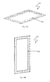
- FIG. 1 illustrates an isometric view of an enclosure assembly with a concealed hinge system, in accordance with an embodiment of the present disclosure
- FIG. 2A and FIG. 2B illustrate isometric views of a hinge from the first pair of hinges used in the enclosure assembly of FIG. 1 ;
- FIG. 2C illustrates an isometric view of a bracket of the hinge of FIG. 2A and 2B ;
- FIG. 2D illustrates a top view of a bracket of the hinge of FIG. 2A and 2B ;
- FIG. 3A illustrates an isometric view of a second hinge used in the enclosure assembly of FIG. 1 ;
- FIG. 3B illustrates another isometric view of the second hinge used in the enclosure assembly of FIG. 1 ;
- FIG. 3C illustrates an isometric view of a sleeve used in the second hinge of FIG. 3B ;
- FIG. 3D illustrates an isometric view of the bracket used in the second hinge of FIG. 3C ;
- FIG. 3E illustrates another isometric view of the sleeve of FIG. 3B ;
- FIG. 4A and FIG. 4B illustrate a sectional view and an isometric view, respectively, of a second hinge in accordance with another embodiment of the present disclosure
- FIG. 5A and FIG. 5B illustrate a sectional view and an isometric view, respectively, of a second hinge in accordance with another embodiment of the present disclosure
- FIG. 6A and FIG. 6B illustrate a sectional view and an isometric view, respectively, of a second hinge in accordance with another embodiment of the present disclosure
- FIG. 7A and FIG. 7B illustrate a sectional view and an isometric view, respectively, of a second hinge in accordance with another embodiment of the present disclosure
- FIG. 8A illustrates an isometric view of a second hinge in accordance with another embodiment of the present disclosure
- FIG. 8B illustrates an isometric view of a bracket, that is to be mounted on the cover, used in the second hinge of FIG. 8A ;
- FIG. 8C illustrates an isometric view of a bracket, that is to be mounted on quadrilateral cabinet, used in the second hinge of FIG. 8A ;
- FIG. 9A illustrates another isometric view of the enclosure assembly of FIG. 1 ;
- FIG. 9B illustrates an isometric view of a mounting feet used in the enclosure assembly of FIG. 9A ;
- FIG. 10A and FIG. 10B illustrate isometric views of the cover having a reinforcing element configured on inner surface of the cover, in accordance with an embodiment of the present disclosure.
- FIG. 11 illustrates an isometric view of the cover having a reinforcing element configured on inner surface of the cover, in accordance with another embodiment of the present disclosure
- FIG. 12 illustrates an isometric view of the cover having a reinforcing element configured on inner surface of the cover, in accordance with yet another embodiment of the present disclosure
- FIG. 13 illustrates an isometric view of the cover having a reinforcing element configured on inner surface of the cover, in accordance with yet another embodiment of the present disclosure.
- FIG. 14 illustrates an isometric view of the cover having a reinforcing element configured on inner surface of the cover, in accordance with yet another embodiment of the present disclosure.
- FIG. 1 illustrates an isometric view of an enclosure assembly with a concealed hinge system (hereinafter referred to as enclosure assembly 100 ), in accordance with an embodiment of the present disclosure.
- the enclosure assembly 100 comprises a quadrilateral cabinet 101 and a cover 102 that is hingeably coupled to the quadrilateral cabinet 101 .
- the quadrilateral cabinet 101 has a base 101 A and a first sidewall 101 B, a second sidewall 101 C, a third sidewall 101 D,v and a fourth sidewall 101 E extending from the base 101 A, thereby defining a hollow space.
- the sidewalls 101 B, 101 C, 101 D and 101 E define a coplanar rim 103 having four corners, viz., a first corner 103 A, a second corner 103 B, a third corner 103 C, and a fourth corner 103 D.
- the cover 102 is configured to swivel along the first sidewall 101 B of the quadrilateral cabinet 101 .
- the enclosure assembly 100 further comprises a plurality mounting feet 104 that facilitates the mounting of the enclosure assembly 100 .
- the enclosure assembly also comprises a plurality of latches 120 that facilitate the fastening of the cover 102 with the quadrilateral cabinet 101 .
- the enclosure assembly 100 may be made from a metallic material like stainless steel to provide a corrosion resistant enclosure.
- the enclosure assembly 100 may also be made from a non-metallic material like polypropylene, high density polyethylene, and the like.
- the enclosure assembly 100 further comprises a first pair of hinges 105 A, 105 B.
- FIG. 2A to FIG. 2C illustrate the different views of a first hinge 105 A of the first pair of hinges 105 A, 105 B.
- the first hinge 105 A is defined by a bracket 106 that is welded to the first corner 103 A of the first sidewall 101 B.
- the bracket 106 is defined by a first footplate 106 A and an integral ear 106 B extending from the first footplate 106 A.
- a recessed aperture 107 is defined on the integral ear 106 B.
- the recessed aperture 107 may be a countersunk hole.
- the enclosure assembly 100 further comprises blocks 108 welded to an inner surface of the cover 102 .
- a tapped blind hole 109 is defined in the block 108 .
- the block 108 is disposed on the inner surface of the cover 102 , such that in an operative configuration, the tapped blind hole 109 is coaxially registered with the recessed aperture 107 defined on the integral ear 106 B.
- a threaded fixture 110 is adapted to pass through the recessed aperture 107 and thread into the tapped blind hole 109 .
- the threaded fixture may be a screw.
- the threaded fixture may be a countersunk screw having a head complementary to the recessed aperture 107 that has a profile of a countersunk hole, such that subsequent to the assembly, the head of the threaded fixture does not protrude out of the recessed aperture 107 .
- a seal of a material like nylon is disposed operatively between the integral ear 106 B and the cover 102 to prevent the direct surface contact of the integral ear 106 B and the cover 102 , thereby reducing friction.
- the second hinge 105 B of the first pair of hinges 105 A, 105 B, another block 108 , and another threaded fixture 110 are also configured near the second corner 103 B of the first sidewall 101 B.
- the first hinge 105 A and the second hinge 105 B of the first pair of hinges 105 A, 105 B, the blocks 108 , and threaded fixtures 110 enable the swiveling action of the cover 102 with respect to the quadrilateral cabinet 101 .
- the enclosure assembly 100 further comprises one or more second hinge 111 operatively disposed along the coplanar rim 103 of the first sidewall 101 B, between the first pair of hinges 105 A, 105 B.
- FIG. 3A and FIG. 3B illustrate the isometric views of the second hinge 111 .
- FIG. 3C to FIG. 3E illustrate different views of the various elements associated with the second hinge.
- the second hinges 111 provide structural integrity and enhanced swiveling action to the hingeable coupling of the cover and the quadrilateral cabinet.
- the second hinge 111 is defined by a second footplate 112 A welded to the coplanar rim 103 on the first sidewall 101 B.
- the second hinge 111 also has arcuate arms 112 B, 112 C extending from the second footplate 112 A. Coaxial apertures 112 E, 112 F are defined in the arcuate arms 112 B, 112 C.
- the enclosure assembly further comprises a sleeve 113 that is weldable to the inner surface of the cover 102 .
- a through-hole 114 is defined in the sleeve 113 .
- the sleeve 113 is disposed on the inner surface of the cover 102 , such that the through-hole 114 defined in the sleeve 113 and the coaxial apertures 112 E, 112 F defined on the arcuate arms 112 B, 112 C are coaxially registered in an operative configuration.
- Two slots 102 G, 102 H are configured on the cover 102 adjacent to the operative ends of the sleeve 113 to accommodate the arcuate arms 112 B, 112 C of the second hinge 111 .
- the arcuate arms 112 B, 112 C do not interfere with the swiveling action of the cover 102
- the second hinges 111 are concealed within the enclosure assembly. More specifically, the second hinge 111 does not protrude out of the enclosure assembly surface.
- a pin 115 is adapted to pass through the coaxial apertures 112 E, 112 F and the through-hole 114 in the operative configuration.
- said recessed apertures 107 in the first pair of hinges 105 A, 105 B, the tapped blind hole 109 defined in the blocks 108 , the coaxial apertures 112 E, 112 F defined in the arcuate arms 112 B, 112 C, and the through-holes 114 are coaxial to enable the swiveling action of the cover 102 over the second, third, and fourth sidewalls to enclose the hollow space defined in the quadrilateral cabinet.
- FIG. 4A and FIG. 4B illustrate a sectional view and an isometric view of a second hinge 211 respectively, in accordance with another embodiment of the present disclosure.
- the second footplate 212 A which is secured on the coplanar rim 203 , defines a first plurality of knuckles.
- the sleeve 213 which is secured on the inner surface of the cover 202 , defines a second plurality of knuckles that has a profile complementary to the first plurality of knuckles.
- the first plurality of knuckles and the second plurality of knuckles are coaxially registered, and a pin is inserted therein to hingeably couple the second footplate 212 A with the sleeve 213 .
- FIG. 5A and FIG. 5B illustrate a sectional view and an isometric view of a second hinge 311 respectively, in accordance with another embodiment of the present disclosure.
- the second footplate 312 A which is secured on the coplanar rim 303 , defines a first plurality of knuckles.
- the sleeve 313 which is secured on the inner surface of the cover 302 , defines a second plurality of knuckles that has a profile complementary to the first plurality of knuckles.
- the first plurality of knuckles and the second plurality of knuckles are coaxially registered, and a pin is inserted therein to hingeably couple the second footplate 312 A with the sleeve 313 .
- FIG. 6A and FIG. 6B illustrate a sectional view and an isometric view of a second hinge 411 respectively, in accordance with another embodiment of the present disclosure.
- the second footplate 412 A which is secured on the coplanar rim 403 , defines a first plurality of knuckles.
- the sleeve 413 which is disposed on the inner surface of the cover 402 , defines a second plurality of knuckles that has a profile complementary to the first plurality of knuckles.
- the first plurality of knuckles and the second plurality of knuckles are coaxially registered, and a pin is inserted therein to hingeably couple the second footplate 412 A with the sleeve 413 .
- FIG. 7A and FIG. 7B illustrate a sectional view and an isometric view of a second hinge 511 respectively, in accordance with another embodiment of the present disclosure.
- Each sleeve 513 A, 513 B has a through-hole 514 A, 514 B formed therein.
- the second footplate 512 A which is secured on the coplanar rim, defines a knuckle. In an operative configuration, the knuckle and the through-holes 514 A, 514 B are coaxially registered and a pin is inserted therein to hingeably couple the second footplate 512 A with the sleeves 513 A, 513 B.
- FIG. 8A illustrates an isometric view of a second hinge in accordance with another embodiment of the present disclosure.
- FIG. 8B illustrates an isometric view of a bracket, which is to be mounted on the cover, used in the second hinge of FIG. 8A .
- FIG. 8C illustrates an isometric view of a bracket, which is to be mounted on quadrilateral cabinet, used in the second hinge of FIG. 8A .
- the sleeves are replaced by brackets 613 A, 613 B and are secured to the inner surface of the cover.
- Each bracket 613 A, 613 B has a base 620 and arms 621 A, 621 B extending from the base 620 .
- Coaxial apertures 622 A, 622 B are configured on the arms 621 A, 621 B.
- the second footplate 612 A has a pair of extended arms 615 A, 615 B extending therefrom.
- Coaxial holes 614 A, 614 B are defined on the extended arms 615 A, 615 B.
- coaxial apertures 622 A, 622 B and the coaxial holes 614 A, 614 B are coaxially registered and a pin is inserted therein to hingeably couple the second footplate 612 A with the brackets 613 A, 613 B.
- FIG. 9A illustrates an isometric view of the enclosure assembly 100 that depicts the configuration of the plurality of mounting feet 104 onto the enclosure assembly 100 .
- FIG. 9B illustrates an isometric view of the mounting feet 104 .
- the plurality of mounting feet 104 is welded onto the enclosure assembly 100 .
- a hole 135 configured on the mounting feet 104 facilitates the mounting of the lifting eye for the purpose of handling during shipping.
- the enclosure assembly 100 of the present disclosure does not involve the use of press-fit inserts for the mounting of hinges or the mounting feet. Also, as explained previously, since the second hinges 111 are concealed within the enclosure assembly 100 and do not protrude out of the enclosure assembly surface, the vertical coupling of enclosures is possible, since the hinges do not interfere with each other, as opposed to the conventional enclosure assemblies.
- latches 120 enables convenient and easy fastening and unfastening of the cover 102 with the quadrilateral cabinet 101 , unlike the conventional enclosure assemblies, where the fastening of the cover with the cabinet is achieved by use of fasteners and the user has to unfasten each and every screw to gain access to the cabinet.
- the cover 102 of the present enclosure assembly 100 of the present disclosure may be adapted to receive reinforcing elements on the inner surface of the cover 102 to enhance the structural integrity thereof.
- FIG. 10A and FIG. 10B illustrate isometric views of the cover 102 .
- a reinforcing element in the form of a reinforcing frame 160 is secured on the inner surface of the cover 102 .
- the reinforcing frame 160 may either be welded or fastened to the inner surface of the cover 102 .
- the fastening of the reinforcing frame 160 on the inner surface of the cover 102 may be done either by means of studs or screws.
- the reinforcing frame 160 of the present embodiment has a rectangular configuration.
- the reinforcing frame 160 may have an L-shape cross-section, a C-shape cross-section, unistrut cross-section, a square cross-section, and the like.
- FIG. 11 illustrates an isometric cover 102 having a reinforcing element configured on inner surface of the cover 102 , in accordance with another embodiment of the present disclosure.
- the reinforcing element in the present embodiment is a reinforcing frame 260 .
- the reinforcing frame 260 comprises cross members 261 , 262 , 263 to enhance the structural integrity of the cover 102 .
- the number of the cross members is not limited to three, and the reinforcing frame 260 may have any number of cross members arranged in any configuration other than that illustrated in FIG. 11 .
- the reinforcing frame 260 and the cross members 261 , 262 , 263 may have an L-shape cross-section, a C-shape cross-section, unistrut cross-section, a square cross-section, and the like.
- the reinforcing frame 260 may either be welded or fastened to the inner surface of the cover 102 .
- the fastening of the reinforcing frame 260 on the inner surface of the cover 102 may be done either by means of studs or screws.
- FIG. 12 illustrates an isometric cover 102 having a reinforcing element configured on inner surface of the cover 102 , in accordance with another embodiment of the present disclosure.
- the reinforcing element in the present embodiment is a reinforcing frame 360 .
- the reinforcing frame 360 comprises cross members 361 , 362 to enhance the structural integrity of the cover 102 .
- the number of the cross members is not limited to two, and the reinforcing frame 360 may have any number of cross members arranged in any configuration other than that illustrated in FIG. 12 .
- the reinforcing frame 360 and the cross members 361 , 362 may have an L-shape cross-section, a C-shape cross-section, unistrut cross-section, a square cross-section, and the like. Furthermore, the reinforcing frame 360 may either be welded or fastened to the inner surface of the cover 102 . The fastening of the reinforcing frame 260 on the inner surface of the cover 102 may be done either by means of studs or screws.
- FIG. 13 illustrates an isometric cover 102 having a reinforcing element configured on inner surface of the cover 102 , in accordance with another embodiment of the present disclosure.
- the reinforcing element in the present embodiment is a reinforcing plate 460 .
- the reinforcing plate 460 may either be welded or fastened to the inner surface of the cover 102 .
- the fastening of the reinforcing frame 460 on the inner surface of the cover 102 may be done either by means of studs or screws.
- the reinforcing plate 460 has a rectangular configuration.
- the shape of the reinforcing plate 460 is not limited to being rectangular, and other configurations of the reinforcing plate 460 such as circular, triangular, elliptical, polygonal, and the like are well within the ambit of the present disclosure.
- FIG. 14 illustrates an isometric cover 102 having a reinforcing element configured on inner surface of the cover 102 , in accordance with another embodiment of the present disclosure.
- the reinforcing element in the present embodiment is a reinforcing frame 560 .
- the reinforcing frame 560 comprises cross members 561 , 562 to enhance the structural integrity of the cover 102 .
- the cross members 561 , 562 are diagonal elements connected to the opposite vertices of the rectangular reinforcing frame 560 .
- the configuration of reinforcing frame 560 may also be achieved by the use of triangular frames.
- the number of the cross members is not limited to two, and the reinforcing frame 560 may have any number of cross members arranged in any configuration other than that illustrated in FIG. 14 .
- the reinforcing frame 560 and the cross members 561 , 562 may have an L-shape cross-section, a C-shape cross-section, unistrut cross-section, a square cross-section, and the like.
- the reinforcing frame 560 may either be welded or fastened to the inner surface of the cover 102 . The fastening of the reinforcing frame 560 on the inner surface of the cover 102 may be done either by means of studs or screws.
- An enclosure assembly with a concealed hinge system in accordance with the present disclosure described herein above has several technical advantages including but not limited to the realization of an enclosure assembly with a concealed hinge system:
Abstract
An enclosure assembly with concealed hinge system comprises a quadrilateral cabinet and a cover that is configured to swivel along a sidewall of the quadrilateral cabinet. The swiveling action of the cover with respect to the quadrilateral cabinet is enabled by the use of a first pair of hinges and at least one second hinge. The first pair of hinges is welded onto the corners of the sidewall, and the at least one second hinge is welded onto the sidewall between the first pair of hinges.
Description
The present application is a national stage entry of PCT/IB2016/052233, filed Apr. 20, 2016, which claims priority to Indian Patent Application Serial No. 1658/MUM/2015 filed Apr. 24, 2015, both of which are incorporated herein by reference for all purposes.
The present disclosure relates to the field of mechanical engineering. In particular, the present disclosure relates to an enclosure assembly with concealed hinge system.
Generally, the conventional enclosure assemblies for electrical systems comprise a cabinet and a cover that is functionally coupled with the cabinet. The cabinet can be made from a metallic material like steel or aluminium, or a non-metallic material like fiber glass or composite glass. Generally, the cabinet has a box-like configuration and is open at one end, which is covered by means of the cover. Conventionally, in a closed configuration, the cover is fastened to the cabinet by means of screws or bolts. One has to unfasten each screw in order open the cover and gain access to the cabinet. The process unfastening all the screws to gain access to the cabinet is cumbersome and time-consuming.
In the conventional enclosure assemblies, the cover is coupled to the cabinet by means of a top hinge and a bottom hinge. These hinges generally protrude out of the enclosure surface and interfere with each other when two or more enclosure assemblies are to be coupled vertically.
Also, the conventional enclosure assemblies involve fixing of a plurality mounting feet on the enclosure assembly to facilitate the mounting of the enclosure assembly. These mounting feet are generally coupled to the enclosure assemblies by means of screws or bolts. These screws or bolts tend to bend for heavier enclosure assemblies, which is not desirable as the enclosure assembly faces the risk of accidental dismounting owing to the failure of the screws or the bolts.
Furthermore, some conventional hinges and mounting feet involve the use of press-fit inserts to facilitate their mounting onto the enclosure assemblies. The usage of these inserts allows the leakage of water inside the cabinet and loosening of components over a period of time. Also, the conventional enclosure assemblies face handling difficulties during shipment due to the lack of mounting provisions for the mounting of the lifting eye.
Hence, there is need for an enclosure assembly with concealed hinge systems that overcomes the above mentioned drawbacks associated with the conventional enclosure assemblies.
Some of the objects of the present disclosure, which at least one embodiment herein satisfies are as follows.
It is an object of the present disclosure to ameliorate one or more problems of the conventional practices or to at least provide a useful alternative.
An object of the present disclosure is to provide an enclosure assembly with a concealed hinge system.
Another object of the present disclosure is to provide an enclosure assembly with a concealed hinge system that does not involve the use of press fit inserts.
Yet another object of the present disclosure is to provide an enclosure assembly with a concealed hinge system that has mounting provisions for mounting a lifting eye for handling the enclosure assemblies during shipment.
Still another object of the present disclosure is to provide an enclosure assembly with a concealed hinge system such that the vertical coupling of two or more enclosure assemblies does not cause interference of the hinges between two adjacent enclosure assemblies.
Other objects and advantages of the present disclosure will be more apparent from the following description when read in conjunction with the accompanying figure, which are not intended to limit the scope of the present disclosure.
The present disclosure envisages an enclosure assembly with a concealed hinge system that comprises a quadrilateral cabinet and a cover. The quadrilateral cabinet is defined by a base and sidewalls extending from the base, wherein the sidewalls define a coplanar rim. The coplanar rim has four corners. The quadrilateral cabinet further defines a hollow space. The cover is configured to swivel along a first sidewall to tightly seal the hollow space. The enclosure assembly further comprises a first pair of hinges defined by brackets welded to a first corner and a second corner of the first sidewall. The brackets are defined by a first footplate and an integral ear extending from the first footplate. A recessed aperture is defined in the integral ear. A block is welded to an inner surface of the cover having a tapped blind hole defined therein. In an operative configuration, the tapped bling hole is coaxial with the recessed aperture defined in the integral ear. The enclosure assembly further comprises a threaded fixture adapted to pass through the recessed aperture and thread into the tapped blind hole. The threaded fixture has a head complementary to the recessed aperture. The enclosure assembly further comprises at least one second hinge having a second footplate welded to the rim of the first sidewall. Arcuate arms extend from the either end of the second footplate wherein the arcuate arms define coaxial apertures. The enclosure assembly further comprises a sleeve weldable to the inner surface of the cover defining a through-hole. A pin is configured to pass through the coaxial apertures and the through-hole. In an operative configuration, the recessed apertures in the first pair of hinges, the tapped blind hole, the coaxial apertures defined in the arcuate arms, and the through-hole are coaxial to enable the swiveling action of the cover over second, third, and fourth sidewalls to enclose the hollow space defined in the quadrilateral cabinet.
An enclosure assembly with a concealed hinge system will now be described with the help of the accompanying drawings in which:
An enclosure assembly with a concealed hinge system in accordance with an embodiment of the present disclosure will now be described with reference to the embodiments, which do not limit the scope and ambit of the disclosure. The description provided is purely by way of example and illustration. The embodiment herein, the various features, and advantageous details thereof are explained with reference to the non-limiting embodiments in the following description. Descriptions of well-known components and processing techniques are omitted so as to not unnecessarily obscure the embodiments herein. The examples used herein are intended merely to facilitate an understanding of ways in which the embodiments herein may be practiced, and to further enable those of skill in the art to practice the embodiments herein. Accordingly, the examples should not be construed as limiting the scope of the embodiments herein.
The enclosure assembly 100 further comprises a first pair of hinges 105A, 105B. FIG. 2A to FIG. 2C illustrate the different views of a first hinge 105A of the first pair of hinges 105A, 105B. The first hinge 105A is defined by a bracket 106 that is welded to the first corner 103A of the first sidewall 101B. The bracket 106 is defined by a first footplate 106A and an integral ear 106B extending from the first footplate 106A. As seen in FIG. 2C , a recessed aperture 107 is defined on the integral ear 106B. In an embodiment, the recessed aperture 107 may be a countersunk hole.
With reference to FIG. 2A , FIG. 2B , and FIG. 2C , the enclosure assembly 100 further comprises blocks 108 welded to an inner surface of the cover 102. A tapped blind hole 109 is defined in the block 108. The block 108 is disposed on the inner surface of the cover 102, such that in an operative configuration, the tapped blind hole 109 is coaxially registered with the recessed aperture 107 defined on the integral ear 106B. A threaded fixture 110 is adapted to pass through the recessed aperture 107 and thread into the tapped blind hole 109. In an embodiment, the threaded fixture may be a screw. In yet another embodiment, the threaded fixture may be a countersunk screw having a head complementary to the recessed aperture 107 that has a profile of a countersunk hole, such that subsequent to the assembly, the head of the threaded fixture does not protrude out of the recessed aperture 107. In the embodiment seen in FIG. 2D , a seal of a material like nylon, is disposed operatively between the integral ear 106B and the cover 102 to prevent the direct surface contact of the integral ear 106B and the cover 102, thereby reducing friction.
In a manner similar to that described in the previous paragraphs, the second hinge 105B of the first pair of hinges 105A, 105B, another block 108, and another threaded fixture 110 are also configured near the second corner 103B of the first sidewall 101B. Thus, the first hinge 105A and the second hinge 105B of the first pair of hinges 105A, 105B, the blocks 108, and threaded fixtures 110 enable the swiveling action of the cover 102 with respect to the quadrilateral cabinet 101.
The enclosure assembly 100 further comprises one or more second hinge 111 operatively disposed along the coplanar rim 103 of the first sidewall 101B, between the first pair of hinges 105A, 105B. FIG. 3A and FIG. 3B illustrate the isometric views of the second hinge 111. FIG. 3C to FIG. 3E illustrate different views of the various elements associated with the second hinge. The second hinges 111 provide structural integrity and enhanced swiveling action to the hingeable coupling of the cover and the quadrilateral cabinet. With reference to FIG. 3A to FIG. 3E , the second hinge 111 is defined by a second footplate 112A welded to the coplanar rim 103 on the first sidewall 101B. The second hinge 111 also has arcuate arms 112B, 112C extending from the second footplate 112A. Coaxial apertures 112E, 112F are defined in the arcuate arms 112B, 112C. The enclosure assembly further comprises a sleeve 113 that is weldable to the inner surface of the cover 102. A through-hole 114 is defined in the sleeve 113. The sleeve 113 is disposed on the inner surface of the cover 102, such that the through-hole 114 defined in the sleeve 113 and the coaxial apertures 112E, 112F defined on the arcuate arms 112B, 112C are coaxially registered in an operative configuration. Two slots 102G, 102H are configured on the cover 102 adjacent to the operative ends of the sleeve 113 to accommodate the arcuate arms 112B, 112C of the second hinge 111. Thus, in an operative configuration, the arcuate arms 112B, 112C do not interfere with the swiveling action of the cover 102, and the second hinges 111 are concealed within the enclosure assembly. More specifically, the second hinge 111 does not protrude out of the enclosure assembly surface. A pin 115 is adapted to pass through the coaxial apertures 112E, 112F and the through-hole 114 in the operative configuration. In the operative configuration, said recessed apertures 107 in the first pair of hinges 105A, 105B, the tapped blind hole 109 defined in the blocks 108, the coaxial apertures 112E, 112F defined in the arcuate arms 112B, 112C, and the through-holes 114 are coaxial to enable the swiveling action of the cover 102 over the second, third, and fourth sidewalls to enclose the hollow space defined in the quadrilateral cabinet.
The enclosure assembly 100 of the present disclosure does not involve the use of press-fit inserts for the mounting of hinges or the mounting feet. Also, as explained previously, since the second hinges 111 are concealed within the enclosure assembly 100 and do not protrude out of the enclosure assembly surface, the vertical coupling of enclosures is possible, since the hinges do not interfere with each other, as opposed to the conventional enclosure assemblies.
The use of latches 120 enables convenient and easy fastening and unfastening of the cover 102 with the quadrilateral cabinet 101, unlike the conventional enclosure assemblies, where the fastening of the cover with the cabinet is achieved by use of fasteners and the user has to unfasten each and every screw to gain access to the cabinet.
Also, the covers of the larger-sized conventional enclosure assembly were prone to bow at the centre due to flimsiness. The cover 102 of the present enclosure assembly 100 of the present disclosure may be adapted to receive reinforcing elements on the inner surface of the cover 102 to enhance the structural integrity thereof.
An enclosure assembly with a concealed hinge system, in accordance with the present disclosure described herein above has several technical advantages including but not limited to the realization of an enclosure assembly with a concealed hinge system:
-
- that does not involve the use of press fit inserts;
- that has mounting provisions for mounting a lifting eye for handling the enclosure assemblies during shipment; and
- such that vertical coupling of two or more enclosure assemblies does not cause interference of the hinges between two adjacent enclosure assemblies.
Throughout this specification the word “comprise”, or variations such as “comprises” or “comprising”, will be understood to imply the inclusion of a stated element, integer or step, or group of elements, integers or steps, but not the exclusion of any other element, integer or step, or group of elements, integers or steps.
The use of the expression “at least” or “at least one” suggests the use of one or more elements or mixture or quantities, as the use may be in the embodiment of the disclosure to achieve one or more of the desired objects or results.
Any discussion of documents, acts, materials, devices, articles or the like that has been included in this specification is solely for the purpose of providing a context for the disclosure. It is not to be taken as an admission that any or all of these matters form part of the prior art base or were common general knowledge in the field relevant to the disclosure, as it existed anywhere before the priority date of this application.
Claims (12)
1. An enclosure assembly with a concealed hinge system, said enclosure assembly comprising:
a quadrilateral cabinet defined by a base and sidewalls extending from said base, said sidewalls defining a coplanar rim, said coplanar rim having four corners, said quadrilateral cabinet further defining a hollow space;
a cover configured to swivel along a first sidewall to tightly seal said hollow space;
a first pair of hinges defined by brackets welded to a first corner and a second corner of said first sidewall, said brackets defined by a first footplate and an integral ear extending from said first footplate, an aperture defined in said integral ear;
a block for each hinge in said first pair of hinges welded to an inner surface of said cover, said block defining a tapped blind hole, wherein in an operative configuration said tapped blind hole is coaxial with said aperture defined in said integral ear;
a threaded fixture for each hinge in said first pair of hinges adapted to pass through said recessed aperture and thread into said tapped blind hole, said fixture defining a head complementary to said aperture;
at least one second hinge having a second footplate welded to said coplanar rim of said first sidewall, arcuate arms extending from either end of said second footplate, said arcuate arms defining coaxial apertures,
a sleeve weldable to said inner surface of said cover defining a through-hole; and
a pin configured to pass through said coaxial apertures and said through-hole in an operative configuration, in which said apertures in said first pair of hinges, said tapped blind hole, said coaxial apertures defined on said arcuate arms, and said through-hole are coaxial to enable swiveling action of said cover over second, third, and fourth sidewalls to enclose said hollow space defined in said quadrilateral cabinet.
2. The enclosure assembly as claimed in claim 1 , wherein said aperture is countersunk.
3. The enclosure assembly as claimed in claim 1 , wherein said threaded fixture is a countersunk screw.
4. The enclosure assembly as claimed in claim 1 , further comprising a seal disposed operatively between said threaded fixture and said aperture to prevent direct surface contact of said threaded fixture and said aperture.
5. The enclosure assembly as claimed in claim 1 , further comprising a plurality of mounting feet welded onto said enclosure assembly to facilitate mounting of said enclosure assembly.
6. The enclosure assembly as claimed in claim 1 , further comprising a plurality of latches to facilitate fastening of said cover with said quadrilateral cabinet.
7. The enclosure assembly as claimed in claim 1 , wherein said cover is adapted to receive reinforcing elements on said inner surface of said cover to enhance the structural integrity of said cover.
8. The enclosure assembly as claimed in claim 7 , wherein said reinforcing element is at least one of a reinforcing frame and a reinforcing plate.
9. The enclosure assembly as claimed in claim 8 , wherein said reinforcing frame has at least one configuration chosen from a group consisting a rectangular configuration, a triangular configuration, and combinations thereof.
10. The enclosure assembly of claim 1 , wherein the aperture is a recessed aperture.
11. The enclosure assembly of claim 1 , wherein the first footplate of the bracket of the first hinge of the first pair of hinges extends horizontally and outwardly from an outside of a first corner of the enclosure assembly; and the first footplate of the bracket of the second hinge of the first pair of hinges extends horizontally and outwardly from an outside of the second corner of the enclosure assembly.
12. The enclosure assembly of claim 11 , wherein the integral ear extends vertically from the first footplate of the bracket of the first hinge of the first pair of hinges, and wherein the integral ear extends vertically from the first footplate of the bracket of the second hinge of the first pair of hinges extends vertically from the first footplate of the second hinge of the first pair of hinges.
Applications Claiming Priority (3)
| Application Number | Priority Date | Filing Date | Title |
|---|---|---|---|
| IN1658/MUM/2015 | 2015-04-24 | ||
| IN1658MU2015 | 2015-04-24 | ||
| PCT/IB2016/052233 WO2016170481A1 (en) | 2015-04-24 | 2016-04-20 | An enclosure assembly with concealed hinge system |
Publications (2)
| Publication Number | Publication Date |
|---|---|
| US20170268268A1 US20170268268A1 (en) | 2017-09-21 |
| US10138665B2 true US10138665B2 (en) | 2018-11-27 |
Family
ID=57143798
Family Applications (1)
| Application Number | Title | Priority Date | Filing Date |
|---|---|---|---|
| US15/514,250 Active 2036-08-02 US10138665B2 (en) | 2015-04-24 | 2016-04-20 | Enclosure assembly with concealed hinge system |
Country Status (3)
| Country | Link |
|---|---|
| US (1) | US10138665B2 (en) |
| DE (1) | DE212016000019U1 (en) |
| WO (1) | WO2016170481A1 (en) |
Families Citing this family (2)
| Publication number | Priority date | Publication date | Assignee | Title |
|---|---|---|---|---|
| WO2016170481A1 (en) * | 2015-04-24 | 2016-10-27 | Appleton Grp, Llc | An enclosure assembly with concealed hinge system |
| CN116540848A (en) * | 2023-05-11 | 2023-08-04 | 北京华美讯通科技有限公司 | Cabinet mounting structure of touch control integrated machine and cabinet mounting method thereof |
Citations (14)
| Publication number | Priority date | Publication date | Assignee | Title |
|---|---|---|---|---|
| US4390114A (en) * | 1981-11-16 | 1983-06-28 | Appleton Electric Company | Hinge construction for electrical enclosures |
| US4704970A (en) * | 1984-04-09 | 1987-11-10 | Thomas A. James | Concealed hinge for lightweight safes |
| US5259091A (en) * | 1992-08-13 | 1993-11-09 | Federal-Hoffman, Inc. | Hinge system for electrical enclosures |
| US5722121A (en) * | 1996-02-27 | 1998-03-03 | Federal-Hoffman, Inc. | Enclosure hinge |
| US5970890A (en) * | 1996-11-27 | 1999-10-26 | Interbold | Method of making secure enclosure for automated banking machine |
| US6118073A (en) * | 1996-03-01 | 2000-09-12 | Hoffman Enclosures, Inc. | Frame assembly for electrical enclosure |
| US6185303B1 (en) * | 1997-12-23 | 2001-02-06 | Francis R. Losey | Enclosure mounting bracket |
| US6321414B1 (en) * | 1999-12-22 | 2001-11-27 | Square D Company | Hinge for electrical enclosure |
| US6438800B1 (en) * | 2001-01-22 | 2002-08-27 | General Electric Company | Door hinge assembly for an electrical appliance enclosure |
| US6979777B2 (en) * | 2003-10-15 | 2005-12-27 | Cooper Wiring Devices, Inc. | Weatherproof electrical enclosure having an adjustable-position cover |
| US7726750B2 (en) * | 2006-06-30 | 2010-06-01 | Hoffman Enclosures, Inc. | Latch for enclosure |
| US7761958B2 (en) * | 2005-12-09 | 2010-07-27 | Allegris Corporation | Hinge and latch mechanism |
| US20150059126A1 (en) * | 2013-08-29 | 2015-03-05 | Electrolux Home Products, Inc | Hinge assembly for a refrigerator |
| US20170268268A1 (en) * | 2015-04-24 | 2017-09-21 | Appleton Grp Llc | An Enclosure Assembly With Concealed Hinge System |
-
2016
- 2016-04-20 WO PCT/IB2016/052233 patent/WO2016170481A1/en active Application Filing
- 2016-04-20 DE DE212016000019.5U patent/DE212016000019U1/en active Active
- 2016-04-20 US US15/514,250 patent/US10138665B2/en active Active
Patent Citations (14)
| Publication number | Priority date | Publication date | Assignee | Title |
|---|---|---|---|---|
| US4390114A (en) * | 1981-11-16 | 1983-06-28 | Appleton Electric Company | Hinge construction for electrical enclosures |
| US4704970A (en) * | 1984-04-09 | 1987-11-10 | Thomas A. James | Concealed hinge for lightweight safes |
| US5259091A (en) * | 1992-08-13 | 1993-11-09 | Federal-Hoffman, Inc. | Hinge system for electrical enclosures |
| US5722121A (en) * | 1996-02-27 | 1998-03-03 | Federal-Hoffman, Inc. | Enclosure hinge |
| US6118073A (en) * | 1996-03-01 | 2000-09-12 | Hoffman Enclosures, Inc. | Frame assembly for electrical enclosure |
| US5970890A (en) * | 1996-11-27 | 1999-10-26 | Interbold | Method of making secure enclosure for automated banking machine |
| US6185303B1 (en) * | 1997-12-23 | 2001-02-06 | Francis R. Losey | Enclosure mounting bracket |
| US6321414B1 (en) * | 1999-12-22 | 2001-11-27 | Square D Company | Hinge for electrical enclosure |
| US6438800B1 (en) * | 2001-01-22 | 2002-08-27 | General Electric Company | Door hinge assembly for an electrical appliance enclosure |
| US6979777B2 (en) * | 2003-10-15 | 2005-12-27 | Cooper Wiring Devices, Inc. | Weatherproof electrical enclosure having an adjustable-position cover |
| US7761958B2 (en) * | 2005-12-09 | 2010-07-27 | Allegris Corporation | Hinge and latch mechanism |
| US7726750B2 (en) * | 2006-06-30 | 2010-06-01 | Hoffman Enclosures, Inc. | Latch for enclosure |
| US20150059126A1 (en) * | 2013-08-29 | 2015-03-05 | Electrolux Home Products, Inc | Hinge assembly for a refrigerator |
| US20170268268A1 (en) * | 2015-04-24 | 2017-09-21 | Appleton Grp Llc | An Enclosure Assembly With Concealed Hinge System |
Non-Patent Citations (2)
| Title |
|---|
| First Generation pre-2017 Prior Art Hinges. |
| PCT International Search Report and Written Opinion, PCT International Application No. PCT/IB2016/052233, dated Sep. 1, 2016, 8 pages. |
Also Published As
| Publication number | Publication date |
|---|---|
| DE212016000019U1 (en) | 2017-07-05 |
| WO2016170481A1 (en) | 2016-10-27 |
| US20170268268A1 (en) | 2017-09-21 |
Similar Documents
| Publication | Publication Date | Title |
|---|---|---|
| US3666134A (en) | Housing for electrical equipment | |
| US20190320796A1 (en) | Economical and Eco-friendly Aluminum Profile Equipment Cabinet | |
| US10138665B2 (en) | Enclosure assembly with concealed hinge system | |
| US20140223840A1 (en) | Reconfigured modular building unit and method | |
| US10826033B2 (en) | Shell, battery module and battery pack | |
| US9699935B1 (en) | Equipment cradles, rack-mounted equipment systems, and related methods | |
| US20100116545A1 (en) | Weather resistant variable enclosure frame | |
| US6204450B1 (en) | Electrical box with fixture support having fitted portion | |
| US20150041463A1 (en) | Multi-piece box base | |
| US20120273436A1 (en) | Data center container | |
| US20200146257A9 (en) | Pet cage | |
| TWI714029B (en) | Canopy and compressor or generator installation provided with such canopy | |
| US20160227662A1 (en) | Electronic device | |
| CN205753003U (en) | A kind of copper bar installation structure | |
| US20120128405A1 (en) | Construction profiles corner assembling system | |
| KR200465733Y1 (en) | a flagpole for baner fixing | |
| US20210259409A1 (en) | Crush-resisting structure and cabinet using the same | |
| US20210068295A1 (en) | Anti-jamming chassis | |
| CN205895784U (en) | Adjustable U type staple bolt | |
| CN210391899U (en) | Box (CN) | |
| US20180002959A1 (en) | Tool-less Hinge Mechanism | |
| CN108966580A (en) | A kind of cabinet framework convenient for assembling | |
| CN209693022U (en) | A kind of speaker combining linking | |
| US11324317B2 (en) | Shelf support and arrangement | |
| CN211369058U (en) | Single-face multi-angle mounting structure |
Legal Events
| Date | Code | Title | Description |
|---|---|---|---|
| AS | Assignment |
Owner name: APPLETON GRP LLC, ILLINOIS Free format text: ASSIGNMENT OF ASSIGNORS INTEREST;ASSIGNORS:HASAN, REHANUL;BAIRD, NEIL AMDREW;KULKARNI, AMIT SHIRISH;SIGNING DATES FROM 20170329 TO 20170405;REEL/FRAME:042204/0412 |
|
| STCF | Information on status: patent grant |
Free format text: PATENTED CASE |
|
| MAFP | Maintenance fee payment |
Free format text: PAYMENT OF MAINTENANCE FEE, 4TH YEAR, LARGE ENTITY (ORIGINAL EVENT CODE: M1551); ENTITY STATUS OF PATENT OWNER: LARGE ENTITY Year of fee payment: 4 |