US1013439A - Metal-planing machine. - Google Patents
Metal-planing machine. Download PDFInfo
- Publication number
- US1013439A US1013439A US59159710A US1910591597A US1013439A US 1013439 A US1013439 A US 1013439A US 59159710 A US59159710 A US 59159710A US 1910591597 A US1910591597 A US 1910591597A US 1013439 A US1013439 A US 1013439A
- Authority
- US
- United States
- Prior art keywords
- platen
- speed
- rocker
- dog
- cutting
- Prior art date
- Legal status (The legal status is an assumption and is not a legal conclusion. Google has not performed a legal analysis and makes no representation as to the accuracy of the status listed.)
- Expired - Lifetime
Links
- 241000282472 Canis lupus familiaris Species 0.000 description 54
- 238000005520 cutting process Methods 0.000 description 26
- 230000007246 mechanism Effects 0.000 description 21
- 230000033001 locomotion Effects 0.000 description 19
- 230000009471 action Effects 0.000 description 11
- 230000001133 acceleration Effects 0.000 description 10
- 239000002184 metal Substances 0.000 description 9
- 230000000979 retarding effect Effects 0.000 description 9
- 230000035939 shock Effects 0.000 description 4
- 238000010586 diagram Methods 0.000 description 3
- 238000009877 rendering Methods 0.000 description 3
- 230000008859 change Effects 0.000 description 2
- 230000009977 dual effect Effects 0.000 description 2
- 230000008520 organization Effects 0.000 description 2
- 230000002441 reversible effect Effects 0.000 description 2
- 229940000425 combination drug Drugs 0.000 description 1
- 150000001875 compounds Chemical class 0.000 description 1
- 230000008878 coupling Effects 0.000 description 1
- 238000010168 coupling process Methods 0.000 description 1
- 238000005859 coupling reaction Methods 0.000 description 1
- 230000000881 depressing effect Effects 0.000 description 1
- 210000005069 ears Anatomy 0.000 description 1
- 230000000694 effects Effects 0.000 description 1
- 230000013011 mating Effects 0.000 description 1
- 238000000034 method Methods 0.000 description 1
- 238000012856 packing Methods 0.000 description 1
Images
Classifications
-
- B—PERFORMING OPERATIONS; TRANSPORTING
- B23—MACHINE TOOLS; METAL-WORKING NOT OTHERWISE PROVIDED FOR
- B23D—PLANING; SLOTTING; SHEARING; BROACHING; SAWING; FILING; SCRAPING; LIKE OPERATIONS FOR WORKING METAL BY REMOVING MATERIAL, NOT OTHERWISE PROVIDED FOR
- B23D7/00—Planing or slotting machines characterised only by constructional features of particular parts
-
- Y—GENERAL TAGGING OF NEW TECHNOLOGICAL DEVELOPMENTS; GENERAL TAGGING OF CROSS-SECTIONAL TECHNOLOGIES SPANNING OVER SEVERAL SECTIONS OF THE IPC; TECHNICAL SUBJECTS COVERED BY FORMER USPC CROSS-REFERENCE ART COLLECTIONS [XRACs] AND DIGESTS
- Y10—TECHNICAL SUBJECTS COVERED BY FORMER USPC
- Y10T—TECHNICAL SUBJECTS COVERED BY FORMER US CLASSIFICATION
- Y10T409/00—Gear cutting, milling, or planing
- Y10T409/50—Planing
- Y10T409/504756—Planing with means to relatively infeed cutter and work
- Y10T409/505248—Planing with means to relatively infeed cutter and work and means to vary rate of infeed
-
- Y—GENERAL TAGGING OF NEW TECHNOLOGICAL DEVELOPMENTS; GENERAL TAGGING OF CROSS-SECTIONAL TECHNOLOGIES SPANNING OVER SEVERAL SECTIONS OF THE IPC; TECHNICAL SUBJECTS COVERED BY FORMER USPC CROSS-REFERENCE ART COLLECTIONS [XRACs] AND DIGESTS
- Y10—TECHNICAL SUBJECTS COVERED BY FORMER USPC
- Y10T—TECHNICAL SUBJECTS COVERED BY FORMER US CLASSIFICATION
- Y10T409/00—Gear cutting, milling, or planing
- Y10T409/50—Planing
- Y10T409/504756—Planing with means to relatively infeed cutter and work
- Y10T409/507872—Planing with means to relatively infeed cutter and work including means causing return stroke
Definitions
- My present invention relatesto a novel method and organization of means'for-mechanically controlling the velocity of movement of the work-supporting) table or platen in a metal-planing machine, whereby the cutting speed or advancing run of the platen, after commencing its'movement, may be accelerated and retarded at desired intermedial places between the extreme limits of its action; the object being to attain high efficiency in the execution ofactual work,
- Another object of this invention is to provide a metal-planer of the class specified, with mechanically controlled means for successively accelerating and. retarding the cutting speed or advancing movement repeatedly, and as often as may be desired, during the course of a single advancing run or stroke of the platen. Also, to provide, in a mechanism of the character described, means for disconnecting the .accelerating and reidle, so that the planer can then be employed as'an ordinary one-speed planer.
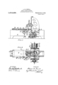
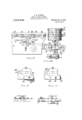
- Fig. 1 the described of a metal-planer embracing invention.
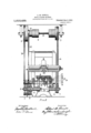
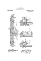
- Fig. 2 is a plan view of the same, a portion of the platen being omitted to reveal parts beneath, and some parts shown in section.
- Fig. 3 represents a transverse vertical section generally at the position of the operating shaft; the section of one side of the frame being taken at a position to show the rockers and dog devices.
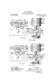
- Figs. 4, 5 6 7 and 85 are continuations of such diagrams, in plan view, including the shaft, pulleys and shipper-actuator means, at positions severally corresponding with the positions of the dogs and rocker devices, as shown in the respective diagrams adjacently delineated.
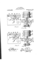
- Figs. 9 and 10 represent separate detail views of the acceleration dog, on somewhat larger scale; illustrating a simple means for disconnecting or rendering the dog non-active, so that the planer can be operated as a single speed planer when desired.
- Fig. .11 is a side view of the platen and series of dogs as arranged for successive acceleration and retardations of the cutting speed.
- FIG. 12 is a fragmentary transverse vertical section view showing, in elevation, the dual armed rocker and the actuating dogs that coact therewith.
- Fig. 13 is a similar view showing the accelerating rocker and dog; and
- Fig. 14 is a similar view showing the reversing rocker and dog.
- the present inventor in a revious invention described and claimed in Letters Patent No. 934,837, ranted September 21, 1909, discloses means for effecting acceleration of the cutting speed immediately after the cutting tool enters the work; but said revious invention had no means for retarding the cutting speed at any intermediate position in the stroke, nor for reducing high speed before the reversing or return movement neither did it include means for a plurality of successive accelerations and retardations of the cutting speed at convenient intervals within the full run of the platen movement.
- My present invention includes the combi: nation of means for increasing the speed of a -metal planer during a portion of its cutting stroke after the cutting-tool has entered into cutting action, and means for retarding this increased speed back to the original cutting 1 speed justbefore the end of the cutting stroke, and while the cutting-tool is in cutting action. Also, to increase and retard this cutting speed at will, at any part of the work to be planed, by an arrangement of dogs on the platen acting through shifting mechanism, levers or rockers operating in bearings in the bed or frame and lever connections to a cam-plate that moves the shipper rods and belt-eyes.
- the operating shaft of the planer is provided with a system of pulleys comprising, in special arrangement, a primary or initial low-speed pulley, a second or high-speed pulley, (and their mating loose pulleys) which speed pulleys are respectively actuated by a low-speed drive-belt and a high-speed drive-belt running from pulleys on a power driven counter-shaft; also a tight and loose pulley for the quick return or reverse action belt, which latter is also run from said counter-shaft; and in combination with the above named pulleys and drive-belts and the belt-shipping mechanism, there is a peculiar and improved organization of shifting rockers and platen-carried dogs adapted for controlling the shifting of the belts to initial or lowspeed cut, and then to high-speed cut as the accelerating dog attached to the platen comes in contact with its shifting rocker or lever; and in similar way when the retarding do attached to the platen
- the letter A denotes the bed or main frame; '13 the'worksupporting table or platen, which is slidably supported upon the bed in well known manner, and moves endwise back and'forth.
- C indicates the cutting tool which is arranged substantially asordinarily employed in machines of this class, or in suitable manner for planing the work W, which is secured to the platen and carried thereby against the tool.
- F and Gr indicate the usual gears whereby movement is imparted to the platen from the operating shaft D, which receives its motion from the power driven counter-shaft E by the system of pulley-s and belts arranged -in the peculiar manner illustrated and here described.
- a broad pulley 1 which is loose upon the shaft
- a pulley 2 which is tight upon the shaft
- a pulley 3 that is loose upon the shaft
- a pulley 4 that is connected with the shaft by an internal roller clutch 5, or equivalent one -way clutching means that gives connection in one direction of rotation and releases in the other direction.
- the face dimension of the pulleys 2 and 3 are each about one half the width of the pulley 1 or 4; and all of the group are preferably'of the same diameter.
- the pulleys 1 and 2 are a pair driven by a belt 10 from a large pulley 11 on the counter-shaft E, and the pulleys 3 and 4 are a pair driven by a belt 12 from a smaller pulley 13 on the countershaft. (See Fig. Hence the belt 10 may be termed the high-speed drive-beltand the belt 12 termed the low-speed drivebelt.
- the counter-shaft E is power driven by a belt on its pulley e, or in other eflicient manner.
- the shipper-rod 15, having suit-able eyes 14, is arranged for endwise movement in well-known manner, for shifting the belts 10 and 12 on their pulleys.
- the shaft D is I also provided with a tight pulley 6 and loose pulley 7 for the return action-belt 16, which runs from a larger pulley 17 upon the counter-shaft; and 18 indicates the shipper-rod having an eye 19 for shifting the return belt.
- the shipper-rods 15 and 18 are worked by swinging arms 8 and 9 linked thereto and actuated by an endwise movable plate 22 having cam slots 23 and 24 therein that engage with the roller studs upon said arms; said plate is supported in suitable bearings 21 rigidly secured to the main frame.
- a rocker or arm 25 mounted on/an axle that extends through and is journaled in the frame, and is furnished at its inner end with a crank connected by a link-bar 27 with the endwise movable plate 22 for shifting the same as the rocker is moved.
- a sec- 4 0nd shifting rocker 26 having two armsor lug members 28 and 29, is mounted upon an acro'ssthe frame, as indicated by dotted lines on Fig. 2.
- the usual hand lever H is arranged on the rocker 26, and a similar handlever H is arranged on shaft h of the opposite side of the machine to facilitate shifting the parts manually.
- a swing-bar rocker 30, termed the accelerating rocker, is pivoted at its lower end upon a suitable fulcrumstud 21 fixed on the frame, while itsupper end is located at a position for cont-act'with a platen-carried actuating dog.
- the rockers and 26 are respectively provided with projecting ears, and are linked together, and to the swing-bar rocker 30 by suitable coupling bars 32 and 33 that are jointed, to the central part of the bar 30.
- Actuation of the rockers and regulation of the cutting speeds is effected mechanically by controlling dogs secured to and adjustable upon the edge of the platen B.
- Said dogs comprise the usual starting dog 34,
- the starting dog 34 is provided with an inclined edge that runs onto and depresses the rocker-25.
- a pin or contact 'member 2' is arranged in the rocker-arm 25, which can be pulled outward to permit the dog 34 to pass without contact when it is desired to run the platen out clear of the tool,'for packing on, changing or examining the work.
- the backing dog 35 is provided with an oppositely disposed inclined edge that runs onto and depresses the rocker 28, when the table has advanced to the end of its stroke.
- the retarding dog 37 is pro- 60 vided with an inclined edge that runs onto,
- the acceler- 6 ating dog 36 is adapted for abutting enaxis stud or shaft h that preferably extends gagement with the upper end of the swingbar rocker 30, for throwing the high-speed driving means into action.
- a means for rendering the accelerating dog 36 temporarily inoperative.
- said dog is provided with an inclined ton no 39 mounted in a groove in the body 0 the dog, pivoted upon a pin 40, and confined to a limit of swing movement by a pin or lug that works in a slot 41.
- the end of the tongue serves as the abutting contact member.
- adjusting device or pivoted cam 42 is arranged at the back of the tongue and adapted to be turned down, as in Fig. 9, to allow the tongue to assume its normal position for.
- the planer can be used either with or without accelerating efiect.
- a plurality in any desired convenient number of accelerating dogs 36, and a corresponding plurality of retarding dogs 37, can be arranged on the platen B for successively and repeatedly effecting the acceleration and retardation operations substantially as above explained; and any convenient number of accelerations and retardations of cutting may thereby be mechanically accomplished between the extremes of the platen movement, by employing dogs of the character specified, at the required intervals upon the platen between the starting dog 34 and reversing dog 35, according to the particular piece of work in hand.
- the arrangement of the dogs and rockers is such that the dogs 36 and 37 contact only when the platen is moving forward, since the action of the reversing dog 35 swings the rockers to a position (Fig. 4) entirely out of reach of said intermediate dogs, except that the loose tongue 39 of the dog 36 slides inertly over the end of the rocker-bar 30.
- the several sets of coacting rocker-arms are, as in ordinary planers, adjusted at posit-ions where it is desired to reverse the direction of the table movement to advance or return.
- the tool C enters the work at such initial low-speed without severe shock or strain as it takes into the metal.
- the dog 36 properly adjusted therefor, then comes into contact with the end of the rocker-bar 30 and changes the mechanlsm to the positions shown in Figs. 6 and 6", thereby throwing the high-speed belt 10 relation, asin Figs. 5+5, and the speed of theadvancing platen is retarded down to the slow or initial cutting speed, so that the tool can pass out of the work at the low or moderate speed; thus avoiding the recoil-strains or spring of the tool, which at high speed is liable to break or snap the tool, or crumble out the metal at the edge where the tool emerges from the work.
- This retardation also reduces the inertia of the moving platen so that the reversing dog 35 is prevented from striking the rocker-arm 28 with such force as to create an undesirable shock in moving the shipper means.
- the shifting movement can be smoothly and easily effected without excessive strain on the parts which compose the shipper mechanism.
- a metal planing machine in combination, with the reciprocating platen, and planer-operating shaft; a low-speed driving means, a high-speed driving means, de vices severally connecting the respective driving means with said shaft, a powerchange of cutting-speed, in the order and for the purpose substantially as set forth.
- a system of control for the cutting speed of the platen comprising a low-speed driving means, a high-speed driving means operatively connected with the planer shaft, a power-shifter mechanism therefor, a series of dogs attached to the platen-and compris ing a plurality of accelerating-dog's, and a plurality of retardingdogs located. between the starting or initial-cut dog and backingdog, and a plurality of shifter operating rockers that are successively actuated by said accelerating and retarding dogs for putting the high-speed drive into action after the tool has entered the work, and for shifting the low-speed drive into action before the cutting tool has completed its out in the work, and preceding the reversing of the platen.
- an acceleration controlling dog comprising a body member adapted for attachment to the platen, an inclined tongue pivoted within a groove 1n said body, and presenting a contact end, a slot and lug limitmg the swing of said tongue, and a tumbler cam or device for retaining said tongue at elevated non-engaging position
Landscapes
- Engineering & Computer Science (AREA)
- Mechanical Engineering (AREA)
- Milling, Drilling, And Turning Of Wood (AREA)
Description
A. M. POWELL.
METAL PLANING MACHINE. APPLICATION FILED NOV.10,'1910.
6SHBETSSHEBT 1.
Patented Jan. 2, 1912;
A. M.'POWELL. METAL PLANING MACHINE. APPLICATION FILED NOV. 10, 1910.
1,013,439. Patented Jan. 2, 1912.
6 SHEETSSHEET 2.
IFIJGSI MTNEJSES/ v A. M. POWELL.
' METAL PLANING MACHINE. APPLIOATION FILED NOV. 10, 1910.
1,01 3,439 Patented Jan; 2, 1912;
6 SHEETS-SHEET 3.
o l4 2 l4 FZG+5 I FIG, 5 Z- W/r/vzssas I ZIIVIVE/VTOR, MQW dizw ,Q 5% 0792mm.
A. M. POWELL. METAL PLANING MACHINE.
APPLICATION FILED NOV. 10, 1910.
Patented Jan. 2, 1912.
[1v VENTOR.
A. M. POWELL. METAL PLANING MACHINE.
APPLIOATION FILED NOV. 10, 1910.
Patented Jan.2,1912.
6 SHEETS-SHEET 5v Wm/5555. 4' MW aMM /Z 5 M491 A. M. POWELL.
METAL PLANING MACHINE.
APPLIOATION FILED NOV. 10, 1910.
6 SHEETSSHEET 6.
W/ zwzssss f/vvs/v roR;
Patented J an. 2, 1912.
ALBERT M. POWELL, F WORCESTER, MASSACHUSETTS.
METAL-PLANING MACHINE.
To all whom it may-concern."
-Be it known that I, ALBERT M. PownLL', a citizen of the United States, residlng at Worcester, in the county -of Worcester and State of Massachusetts, have invented new ,specjfication of Letters Patent.
and useful Improvements in Metal-Planing j Machines, of which the following is a specification, reference being made therein to the T accompanying drawings.
My present invention relatesto a novel method and organization of means'for-mechanically controlling the velocity of movement of the work-supporting) table or platen in a metal-planing machine, whereby the cutting speed or advancing run of the platen, after commencing its'movement, may be accelerated and retarded at desired intermedial places between the extreme limits of its action; the object being to attain high efficiency in the execution ofactual work,
- while avoiding shocks and recoil strains warding mechanism; or rendering the same upon the-cutting tool, such as might tend to fracture the tool, or cause the breaking out or crumbling of the metal operated upon as the tool enters and leaves the same.
' Another object of this invention is to provide a metal-planer of the class specified, with mechanically controlled means for successively accelerating and. retarding the cutting speed or advancing movement repeatedly, and as often as may be desired, during the course of a single advancing run or stroke of the platen. Also, to provide, in a mechanism of the character described, means for disconnecting the .accelerating and reidle, so that the planer can then be employed as'an ordinary one-speed planer.
I attain these objects by mechanism, the nature and operation of which is illustrated in the drawings, and explained in detail in the following description; the articular subject-matter claimed being de nitely set is a. front view In the drawin --Figure 1 the described of a metal-planer embracing invention. Fig. 2 is a plan view of the same, a portion of the platen being omitted to reveal parts beneath, and some parts shown in section. Fig. 3 represents a transverse vertical section generally at the position of the operating shaft; the section of one side of the frame being taken at a position to show the rockers and dog devices. Figs. 4, .5, 6,.7
and 8 are detail front view diagrams of the Patented an. 2,1912.
Application filed November 10, 1910. Serial No. 591,597.
platen, dogs and rocker devices illustrating the relative positions thereof at differentstages of their action; and Figs. 4, 5 6 7 and 85 are continuations of such diagrams, in plan view, including the shaft, pulleys and shipper-actuator means, at positions severally corresponding with the positions of the dogs and rocker devices, as shown in the respective diagrams adjacently delineated. Figs. 9 and 10 represent separate detail views of the acceleration dog, on somewhat larger scale; illustrating a simple means for disconnecting or rendering the dog non-active, so that the planer can be operated as a single speed planer when desired. Fig. .11 is a side view of the platen and series of dogs as arranged for successive acceleration and retardations of the cutting speed. Fig. 12 is a fragmentary transverse vertical section view showing, in elevation, the dual armed rocker and the actuating dogs that coact therewith. Fig. 13 is a similar view showing the accelerating rocker and dog; and Fig. 14 is a similar view showing the reversing rocker and dog.
In the ordinary one-speed-cut planer it is impossible to make the cutting speed greater than the cutting-tool will stand without breaking down from the shock or blow incident to the work striking its cutting edge as it enters into cut; and inasmuch as the intensity of this blow increases as the square of the velocity of platen movement, it has not heretofore been practicable to get a cut ting speed on such a planer as high as is accomplished on the high-speed. engine lathe; consequently it has been impossible heretofore to get as great efliciency of execution out of the planing machine as is possible with some engine lathes.
The present inventor, in a revious invention described and claimed in Letters Patent No. 934,837, ranted September 21, 1909, discloses means for effecting acceleration of the cutting speed immediately after the cutting tool enters the work; but said revious invention had no means for retarding the cutting speed at any intermediate position in the stroke, nor for reducing high speed before the reversing or return movement neither did it include means for a plurality of successive accelerations and retardations of the cutting speed at convenient intervals within the full run of the platen movement.
Said previous invention was, it is believed,
the old type of planer, its greatest utility I was on work to be planed in long continuous pieces, and it was not fully suited to work involving a series of planed surfaces and unplaned intervals. By the present invention it is possible to obtain similar advantages on short pieces, or spots ,on work where there are long distances between planed portions, wl1ere the tool runs idle, since the accelerating mechanism can be used to get over these spaces quickly, then a retard to the low speed just before entering into another out, after which it may be accelerated to the next spot to be planed, andagain retarded before the tool passes out of the work.
My present invention includes the combi: nation of means for increasing the speed of a -metal planer during a portion of its cutting stroke after the cutting-tool has entered into cutting action, and means for retarding this increased speed back to the original cutting 1 speed justbefore the end of the cutting stroke, and while the cutting-tool is in cutting action. Also, to increase and retard this cutting speed at will, at any part of the work to be planed, by an arrangement of dogs on the platen acting through shifting mechanism, levers or rockers operating in bearings in the bed or frame and lever connections to a cam-plate that moves the shipper rods and belt-eyes.
In accordance with the preferred form of embodiment of my invent-ion the operating shaft of the planer is provided with a system of pulleys comprising, in special arrangement, a primary or initial low-speed pulley, a second or high-speed pulley, (and their mating loose pulleys) which speed pulleys are respectively actuated by a low-speed drive-belt and a high-speed drive-belt running from pulleys on a power driven counter-shaft; also a tight and loose pulley for the quick return or reverse action belt, which latter is also run from said counter-shaft; and in combination with the above named pulleys and drive-belts and the belt-shipping mechanism, there is a peculiar and improved organization of shifting rockers and platen-carried dogs adapted for controlling the shifting of the belts to initial or lowspeed cut, and then to high-speed cut as the accelerating dog attached to the platen comes in contact with its shifting rocker or lever; and in similar way when the retarding do attached to the platen comes in contact with its shift-ing rocker it effects the shifting of the mechanism to retard or reduce the cutting-speed back to its original or normal low-cut velocity, thus affording capacity for accelerating and retarding the advancing or cutting movement at desired positions, and as often as may be desired at intervals between the starting and reversing points of the platen stroke.
Referring to the drawings, the letter A denotes the bed or main frame; '13 the'worksupporting table or platen, which is slidably supported upon the bed in well known manner, and moves endwise back and'forth. C indicates the cutting tool which is arranged substantially asordinarily employed in machines of this class, or in suitable manner for planing the work W, which is secured to the platen and carried thereby against the tool.
F and Gr indicate the usual gears whereby movement is imparted to the platen from the operating shaft D, which receives its motion from the power driven counter-shaft E by the system of pulley-s and belts arranged -in the peculiar manner illustrated and here described. Upon the shaft D there is arranged a broad pulley 1 which is loose upon the shaft; a pulley 2 which is tight upon the shaft; a pulley 3 that is loose upon the shaft; and a pulley 4 that is connected with the shaft by an internal roller clutch 5, or equivalent one -way clutching means that gives connection in one direction of rotation and releases in the other direction. The face dimension of the pulleys 2 and 3 are each about one half the width of the pulley 1 or 4; and all of the group are preferably'of the same diameter. The pulleys 1 and 2 are a pair driven by a belt 10 from a large pulley 11 on the counter-shaft E, and the pulleys 3 and 4 are a pair driven by a belt 12 from a smaller pulley 13 on the countershaft. (See Fig. Hence the belt 10 may be termed the high-speed drive-beltand the belt 12 termed the low-speed drivebelt. The counter-shaft E is power driven by a belt on its pulley e, or in other eflicient manner.
The shipper-rod 15, having suit-able eyes 14, is arranged for endwise movement in well-known manner, for shifting the belts 10 and 12 on their pulleys. The shaft D is I also provided with a tight pulley 6 and loose pulley 7 for the return action-belt 16, which runs from a larger pulley 17 upon the counter-shaft; and 18 indicates the shipper-rod having an eye 19 for shifting the return belt. The shipper-rods 15 and 18 are worked by swinging arms 8 and 9 linked thereto and actuated by an endwise movable plate 22 having cam slots 23 and 24 therein that engage with the roller studs upon said arms; said plate is supported in suitable bearings 21 rigidly secured to the main frame. The
shipper-rods move endwise in their bearings accordingly as the inclined slotsand stages 5 23 and 24 of the cameplate 22 change the relation of the swing-arms when said camplate is shifted endwise one way or the other in greater or less degree. The cam-plate, swing-arms and shipper-rods are arranged as heretofore practiced. A
In the controlling mechanism there is employed a rocker or arm 25 mounted on/an axle that extends through and is journaled in the frame, and is furnished at its inner end with a crank connected by a link-bar 27 with the endwise movable plate 22 for shifting the same as the rocker is moved. A sec- 4 0nd shifting rocker 26 having two armsor lug members 28 and 29, is mounted upon an acro'ssthe frame, as indicated by dotted lines on Fig. 2. The usual hand lever H is arranged on the rocker 26, and a similar handlever H is arranged on shaft h of the opposite side of the machine to facilitate shifting the parts manually. A swing-bar rocker 30, termed the accelerating rocker, is pivoted at its lower end upon a suitable fulcrumstud 21 fixed on the frame, while itsupper end is located at a position for cont-act'with a platen-carried actuating dog. The rockers and 26 are respectively provided with projecting ears, and are linked together, and to the swing-bar rocker 30 by suitable coupling bars 32 and 33 that are jointed, to the central part of the bar 30.
Actuation of the rockers and regulation of the cutting speeds is effected mechanically by controlling dogs secured to and adjustable upon the edge of the platen B. Said dogs comprise the usual starting dog 34,
, herein termed the initial-cut dog, and a backing dog 35; and also in accordance with my invention, one or more dogs 36, herein termed the accelerating dog, and one or more dogs 37, herein termed the retarding dog. The starting dog 34 is provided with an inclined edge that runs onto and depresses the rocker-25. A pin or contact 'member 2' is arranged in the rocker-arm 25, which can be pulled outward to permit the dog 34 to pass without contact when it is desired to run the platen out clear of the tool,'for packing on, changing or examining the work. The backing dog 35 is provided with an oppositely disposed inclined edge that runs onto and depresses the rocker 28, when the table has advanced to the end of its stroke. The retarding dog 37 is pro- 60 vided with an inclined edge that runs onto,
or engages-with and depresses the rocker- -Iarm 29 to retroactively throw the actuated parts to position corresponding with the po- ";-.,sition assumed for initial cut. The acceler- 6 ating dog 36 is adapted for abutting enaxis stud or shaft h that preferably extends gagement with the upper end of the swingbar rocker 30, for throwing the high-speed driving means into action.
Since there are times when it is desired to employ the planer upon work where an accelerating act-ion is not, for the time being, required, a means is provided for rendering the accelerating dog 36 temporarily inoperative. As shown in Figs. 9 and 10, said dog is provided with an inclined ton no 39 mounted in a groove in the body 0 the dog, pivoted upon a pin 40, and confined to a limit of swing movement by a pin or lug that works in a slot 41. The end of the tongue serves as the abutting contact member. An
adjusting device or pivoted cam 42 is arranged at the back of the tongue and adapted to be turned down, as in Fig. 9, to allow the tongue to assume its normal position for.
contact, or turned up, as in Fig. 10, for retaining the tongue in'elevated or non-contacting position. When thus elevated the dog 36 will pass the rocker-bar 30 without contacting therewith, but when the tongue is down the contact is effective for moving the rocker and starting the acceleration. Hence by merely shifting the device 42 the planer can be used either with or without accelerating efiect.
A plurality in any desired convenient number of accelerating dogs 36, and a corresponding plurality of retarding dogs 37, can be arranged on the platen B for successively and repeatedly effecting the acceleration and retardation operations substantially as above explained; and any convenient number of accelerations and retardations of cutting may thereby be mechanically accomplished between the extremes of the platen movement, by employing dogs of the character specified, at the required intervals upon the platen between the starting dog 34 and reversing dog 35, according to the particular piece of work in hand. The arrangement of the dogs and rockers is such that the dogs 36 and 37 contact only when the platen is moving forward, since the action of the reversing dog 35 swings the rockers to a position (Fig. 4) entirely out of reach of said intermediate dogs, except that the loose tongue 39 of the dog 36 slides inertly over the end of the rocker-bar 30.
The several sets of coacting rocker-arms are, as in ordinary planers, adjusted at posit-ions where it is desired to reverse the direction of the table movement to advance or return.
The operation is as follows: Assuming that the parts are at positions shown in Fig. 4 and Fig. 4 the platen is then moving backward and ready for changing to a new cut. The belts 10 and 12 are on the loose pulleys 1 and 3, and the return is being driven by the belt 16 on the tight pulley 6. The dog 34 runs onto the pin or contact member 2' of rocker 25, depressing said rocker and moving the connected parts to the positions shown in Figs. 5 and 5*. This change shifts .the return belt 16 onto. its loose pulley 7, and the low-speed belt 12 from its loose pulley 3 onto the clutch pulley 4;, thereby startin the forward movement of the platen. Figs. 5 and 5 represent the platen as started forward at initial or low-speed, the first accelerating dog 36 ready to act against the swing-bar rocker 30.
' As the platen commences its forward movement at normal low speed, the tool C enters the work at such initial low-speed without severe shock or strain as it takes into the metal. The dog 36, properly adjusted therefor, then comes into contact with the end of the rocker-bar 30 and changes the mechanlsm to the positions shown in Figs. 6 and 6", thereby throwing the high-speed belt 10 relation, asin Figs. 5+5, and the speed of theadvancing platen is retarded down to the slow or initial cutting speed, so that the tool can pass out of the work at the low or moderate speed; thus avoiding the recoil-strains or spring of the tool, which at high speed is liable to break or snap the tool, or crumble out the metal at the edge where the tool emerges from the work. This retardation also reduces the inertia of the moving platen so that the reversing dog 35 is prevented from striking the rocker-arm 28 with such force as to create an undesirable shock in moving the shipper means. Hence the shifting movement can be smoothly and easily effected without excessive strain on the parts which compose the shipper mechanism.
What I claim and desire to secure by Letters Patent, is
1. In a metal planing machine, in combination, with the reciprocating platen, and planer-operating shaft; a low-speed driving means, a high-speed driving means, de vices severally connecting the respective driving means with said shaft, a powerchange of cutting-speed, in the order and for the purpose substantially as set forth.
2. In a metal-planing machine, a system of control for the cutting speed of the platen, comprising a low-speed driving means, a high-speed driving means operatively connected with the planer shaft, a power-shifter mechanism therefor, a series of dogs attached to the platen-and compris ing a plurality of accelerating-dog's, and a plurality of retardingdogs located. between the starting or initial-cut dog and backingdog, and a plurality of shifter operating rockers that are successively actuated by said accelerating and retarding dogs for putting the high-speed drive into action after the tool has entered the work, and for shifting the low-speed drive into action before the cutting tool has completed its out in the work, and preceding the reversing of the platen.
3. The combination, with the planer-operating shaft, the normal low-speed driving means, a high-speed driving means, and a quick-return driving means; of mechanism for shifting the several driving-means into and out of effective action, and devices for controllingsaid shifting mechanism co Inprising a compound rocker mechanism including a single armed rocker, a dual armed rocker and a swing-bar rocker coupled therewith, and a series of platen-carried dogs including, in addition to the usual starting and reversing dogs, the acceleration and retardation dogs, each adjustably secured to the platen and cooperating with said rockers and shifting mechanism for effecting acceleration and retardation of cutting-speed while the tool is cutting in the work.
4. In a metal planing machine, the combination with the platen, platen-movinggears,
its operating shaft, and a belt-actuating means; of a high speed drive-belt and a lowspeed drive-belt; pulleys for said drive-belts mounted upon said shaft, one of said pulleys having a one-way clutch connection therewith, a' shipper for said belts, a means for shifting said shipper consisting of a that controls the shipper mechanism to bring-the high-speed drive into action, and
a retardation-dog and rocker that controls the shipper mechanism to reinstate the lowspeed drive into actlon, said dogs carried on the platen and acting at intermediate positions in respect to the'dogs that control the shipper mechanism at the respective limits of the platen movement.
5. In a metal-planing machine, the com bination, with the pl'aten, the operatingshaft, and means for transmitting motion from said shaft tothe platen; of agrou of driving pulleys mounted upon said sha t and comprising a first pair including a loose pulley and a tight pulley, a second pair including a loose pulley and a one-Way releasable clutch pulley, a power-driven counter shaft carrying drive-pulleys of larger and smaller diameters; a high-speeddrivebelt from the larger counter pulley to thefirst pair of pulleys, a low-s eed drive-belt from the smaller counter p ey to said sec- 0nd pair of pulleys, a belt-shifting mechanism including inclines and stages adapted for giving extreme and intermediate shiftpositions, and means carried upon the platen, for controlling the belt-shifting mechanism to give successive accelerated 'movement and retardation offorward or cutting speed between the starting and the reversing positions of the platen, substantially as set forth.
6. In a metal-planer having a horizontally reciprocating platen, and shi per-actuating mechanism, and 'IOCkGT-dGVlCGS operatively connected with the power shifting mechanism of the platen-operating means; the combination, with said laten and rocker-devices, of an acceleration controlling dog comprising a body member adapted for attachment to the platen, an inclined tongue pivoted within a groove 1n said body, and presenting a contact end, a slot and lug limitmg the swing of said tongue, and a tumbler cam or device for retaining said tongue at elevated non-engaging position,
substantially. as set forth.
Witness my hand this 8th day of November, 1910.
Witnesses:
CHAS. H. Bommzmn, A. DAVIS.
ALBERT MQPOWELL.
Priority Applications (1)
| Application Number | Priority Date | Filing Date | Title |
|---|---|---|---|
| US59159710A US1013439A (en) | 1910-11-10 | 1910-11-10 | Metal-planing machine. |
Applications Claiming Priority (1)
| Application Number | Priority Date | Filing Date | Title |
|---|---|---|---|
| US59159710A US1013439A (en) | 1910-11-10 | 1910-11-10 | Metal-planing machine. |
Publications (1)
| Publication Number | Publication Date |
|---|---|
| US1013439A true US1013439A (en) | 1912-01-02 |
Family
ID=3081747
Family Applications (1)
| Application Number | Title | Priority Date | Filing Date |
|---|---|---|---|
| US59159710A Expired - Lifetime US1013439A (en) | 1910-11-10 | 1910-11-10 | Metal-planing machine. |
Country Status (1)
| Country | Link |
|---|---|
| US (1) | US1013439A (en) |
Cited By (1)
| Publication number | Priority date | Publication date | Assignee | Title |
|---|---|---|---|---|
| US10848619B2 (en) | 2019-03-07 | 2020-11-24 | At&T Intellectual Property I, L.P. | Communications network security for handling proxy voice calls |
-
1910
- 1910-11-10 US US59159710A patent/US1013439A/en not_active Expired - Lifetime
Cited By (1)
| Publication number | Priority date | Publication date | Assignee | Title |
|---|---|---|---|---|
| US10848619B2 (en) | 2019-03-07 | 2020-11-24 | At&T Intellectual Property I, L.P. | Communications network security for handling proxy voice calls |
Similar Documents
| Publication | Publication Date | Title |
|---|---|---|
| US1115972A (en) | Automatic turret-lathe. | |
| GB1200440A (en) | Improvements in or relating to an arrangement on an automatic lathe for feeding bar stock | |
| US1013439A (en) | Metal-planing machine. | |
| GB632869A (en) | Lathes and like machine tools | |
| GB1534283A (en) | Mining machine | |
| US2584629A (en) | Power-operated mechanism for moving a tool slide and tool slide carriage | |
| US3146677A (en) | Shaping and slotting machines | |
| US2677281A (en) | Tool-slide actuating mechanism for lathes or other machines | |
| US917468A (en) | High-speed attachment for lathes. | |
| US627299A (en) | echols | |
| US617408A (en) | Metal-turning machine | |
| GB1101292A (en) | Multiple-spindle automatic lathes | |
| US856656A (en) | Carriage-feed mechanism. | |
| US1199252A (en) | Automatic turrett-lathe. | |
| SU428912A1 (en) | SPINDLE MACHINE FOR CUTTING SCREWS | |
| US962842A (en) | Power-transmitting device. | |
| US1985225A (en) | Milling machine | |
| US2481153A (en) | Driving mechanism for automatic bar stock machines and the like | |
| US1275404A (en) | Portable shaper. | |
| SU92105A1 (en) | Automatic machine for abrading with an emery wheel the internal cylindrical surfaces of ring blanks | |
| US773240A (en) | Driving connection for metal-planing machines. | |
| US628734A (en) | Speed-changing mechanism for screw-machines. | |
| US914948A (en) | Rotary planing-machine. | |
| US2592799A (en) | Variable-speed transmission | |
| US1574786A (en) | Speed-changing cam-driving mechanism |