US101323A - Improvement in water-meters - Google Patents
Improvement in water-meters Download PDFInfo
- Publication number
- US101323A US101323A US101323DA US101323A US 101323 A US101323 A US 101323A US 101323D A US101323D A US 101323DA US 101323 A US101323 A US 101323A
- Authority
- US
- United States
- Prior art keywords
- water
- cylinder
- arms
- case
- meters
- Prior art date
- Legal status (The legal status is an assumption and is not a legal conclusion. Google has not performed a legal analysis and makes no representation as to the accuracy of the status listed.)
- Expired - Lifetime
Links
- XLYOFNOQVPJJNP-UHFFFAOYSA-N water Substances O XLYOFNOQVPJJNP-UHFFFAOYSA-N 0.000 description 10
- 238000005192 partition Methods 0.000 description 4
- 238000012856 packing Methods 0.000 description 3
- 238000010276 construction Methods 0.000 description 1
- 239000011521 glass Substances 0.000 description 1
- 239000000463 material Substances 0.000 description 1
Images
Classifications
-
- G—PHYSICS
- G01—MEASURING; TESTING
- G01F—MEASURING VOLUME, VOLUME FLOW, MASS FLOW OR LIQUID LEVEL; METERING BY VOLUME
- G01F1/00—Measuring the volume flow or mass flow of fluid or fluent solid material wherein the fluid passes through a meter in a continuous flow
- G01F1/05—Measuring the volume flow or mass flow of fluid or fluent solid material wherein the fluid passes through a meter in a continuous flow by using mechanical effects
- G01F1/06—Measuring the volume flow or mass flow of fluid or fluent solid material wherein the fluid passes through a meter in a continuous flow by using mechanical effects using rotating vanes with tangential admission
Definitions
- vI inclose this apparatus in a suitable case which is divided internally into two compartments by a parti tion,.in which the upper end of the cylinder revolves, iitted and packed ina proper manner, so that the water, which ows into the upper part of vthecase,
- the water may be drawn off from the bottonl'of the case, or at any other desired point.
- Suitable registering mechanism is placed in the upper part of the case,and connected to the revolving cylinder..
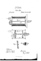
- Figure 1 is a perspective view of' the meter, with its connections.
- Figure 2 is a vertical transverse section, showing the construction and arrangement of the internal parts.”
- Figure 3 is an elevation, showing the revolving arms lC C and openings O O.
- FIG 4 shows the pointed bearing F as connected to the discharge-pipe I).
- A is the case or body of the meter, iliade oi' glass 0r any suitable material, divided by the partition H.
- E is the pipe lthrough which the Water enters the meter, the arrows showing the direction of its flow.
Landscapes
- Physics & Mathematics (AREA)
- Fluid Mechanics (AREA)
- General Physics & Mathematics (AREA)
- Measuring Volume Flow (AREA)
Description
@anni @Militia GEORGE W. SMITH, OF NORWICH, CONNECTICUT.
Letters Patent No. 101,323, :Za/ted March 29, 1870.
IMPROVEMENT IN WATER-METERS.
The Schedule referred to in these Letters Patent and making part of the same ing cylinder, provided with two or any suitable num- -ber of radiating hollow arms communicating internally with the cylinder and having their outer ends opening in opposite directions, the cylinder and arms being adjusted to 'revolve freely upon suitable bearings.-
vI inclose this apparatus in a suitable case which is divided internally into two compartments by a parti tion,.in which the upper end of the cylinder revolves, iitted and packed ina proper manner, so that the water, which ows into the upper part of vthecase,
'is discharged through the cylinder and arms into the water in the lower part of the case, thereby causing the apparatus to revolve in the water, the number of revolutions indicatiugthe volumel of water which passes through the meter.
The water may be drawn off from the bottonl'of the case, or at any other desired point.
Suitable registering mechanism is placed in the upper part of the case,and connected to the revolving cylinder..
In the accompanying drawings- Figure 1 is a perspective view of' the meter, with its connections.
Figure 2 is a vertical transverse section, showing the construction and arrangement of the internal parts."
. Figure 3 is an elevation, showing the revolving arms lC C and openings O O.
Figure 4 shows the pointed bearing F as connected to the discharge-pipe I).
A is the case or body of the meter, iliade oi' glass 0r any suitable material, divided by the partition H.
Below the partition are placed the hollow cylinder and arms B C C, revolving upon the p oint F, supported .by the bearing G, and provided at the point P with proper packing.
In the upper part of the case is placed the registering mechanism I I.
E is the pipe lthrough which the Water enters the meter, the arrows showing the direction of its flow.
l I do not claim as 4new the cylinder and arms B C C.
I claim as my invention- 1. The combination and arrangement of the upright hollow cylinder and arms B C C revolving in water in the lower chamber of the 'case A, having the upper end of the cylinder opening into the upper chamber of the case, and provided with packing, which, while, it permits the cylinder to revolve freely, causes all the water supplied to the upper chamber-to pass through the revolving cylinder and arms into the water in the lower chamber, whence it is discharged,
substantially as and for the purposes hereiubcfore set forth.
2 The combination in a water-meter of the revolving cylinder B, arms C C, partition H, bearings F and G, packing l), and registering mechanism I, all arranged and Voperating in the water within the case A, substantially as and for the purposes herein described.
GEORGE W. SMITH.
lVitnesses:
WEBSTER PARK, THOMAS E. SPARKS.
Publications (1)
| Publication Number | Publication Date |
|---|---|
| US101323A true US101323A (en) | 1870-03-29 |
Family
ID=2170797
Family Applications (1)
| Application Number | Title | Priority Date | Filing Date |
|---|---|---|---|
| US101323D Expired - Lifetime US101323A (en) | Improvement in water-meters |
Country Status (1)
| Country | Link |
|---|---|
| US (1) | US101323A (en) |
-
0
- US US101323D patent/US101323A/en not_active Expired - Lifetime
Similar Documents
| Publication | Publication Date | Title |
|---|---|---|
| US101323A (en) | Improvement in water-meters | |
| KR890004778A (en) | Hand spray with rotary brush set | |
| ES2332983T3 (en) | TEST DEVICE FOR ULTRASOUND TEST OF BAR MATERIAL. | |
| US510027A (en) | Corn-popper | |
| US638073A (en) | Rotary meter. | |
| US689572A (en) | Centrifugal machine. | |
| US1462063A (en) | Apparatus for aerating liquids | |
| US1799635A (en) | Liquid-flow meter | |
| US302220A (en) | Centrifugal reel | |
| US1073387A (en) | Water-meter. | |
| US433088A (en) | Water meter with revolving piston | |
| US68666A (en) | Improved combination apparatus for carbureting air | |
| US673173A (en) | Water-meter. | |
| US1076297A (en) | Agitating device for roasting-furnaces or the like. | |
| US634967A (en) | Turbine water-wheel. | |
| US682528A (en) | Ore-sampling machine. | |
| US107769A (en) | Improvement in liquid-meters | |
| US901808A (en) | Churn. | |
| US156453A (en) | Improvement in drop-light gasaliers | |
| US996787A (en) | Water-motor. | |
| US683645A (en) | Rotary lawn-sprinkler. | |
| US743316A (en) | Tubulous steam-generator. | |
| US4593A (en) | Royal e | |
| US436419A (en) | Centrifugal separator | |
| US110912A (en) | Improvement in rotary engines |