US1013050A - System and apparatus for generating and burning oil-gas. - Google Patents
System and apparatus for generating and burning oil-gas. Download PDFInfo
- Publication number
- US1013050A US1013050A US63629311A US1911636293A US1013050A US 1013050 A US1013050 A US 1013050A US 63629311 A US63629311 A US 63629311A US 1911636293 A US1911636293 A US 1911636293A US 1013050 A US1013050 A US 1013050A
- Authority
- US
- United States
- Prior art keywords
- oil
- chamber
- burner
- gas
- generating
- Prior art date
- Legal status (The legal status is an assumption and is not a legal conclusion. Google has not performed a legal analysis and makes no representation as to the accuracy of the status listed.)
- Expired - Lifetime
Links
- 239000003921 oil Substances 0.000 description 49
- 239000002184 metal Substances 0.000 description 6
- 238000010276 construction Methods 0.000 description 5
- 238000010438 heat treatment Methods 0.000 description 5
- 239000000203 mixture Substances 0.000 description 2
- 229920000136 polysorbate Polymers 0.000 description 2
- 241000233805 Phoenix Species 0.000 description 1
- 239000010779 crude oil Substances 0.000 description 1
- 239000000295 fuel oil Substances 0.000 description 1
- 239000003595 mist Substances 0.000 description 1
- 230000001105 regulatory effect Effects 0.000 description 1
- 239000007787 solid Substances 0.000 description 1
- 239000000725 suspension Substances 0.000 description 1
Images


Classifications
-
- F—MECHANICAL ENGINEERING; LIGHTING; HEATING; WEAPONS; BLASTING
- F02—COMBUSTION ENGINES; HOT-GAS OR COMBUSTION-PRODUCT ENGINE PLANTS
- F02M—SUPPLYING COMBUSTION ENGINES IN GENERAL WITH COMBUSTIBLE MIXTURES OR CONSTITUENTS THEREOF
- F02M31/00—Apparatus for thermally treating combustion-air, fuel, or fuel-air mixture
- F02M31/02—Apparatus for thermally treating combustion-air, fuel, or fuel-air mixture for heating
- F02M31/16—Other apparatus for heating fuel
- F02M31/18—Other apparatus for heating fuel to vaporise fuel
Definitions
- FIG. 1 is a side elevation of a system for mixing and feeding oil gas to a suitable burner contained within a furnace
- Fig. 2 is a side elevation of a system for generating and storing oil gas
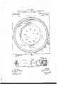
- Fig. 3 is a plan view of a burner constructed in accordance with the present invention
- Fig. 4 is a side elevation of the burner
- 5 is a horizontal section of the same taken on the line 5-5 in Fig. 4
- the gas generated is formed from fuel or crude oil.
- this is stored in tanks 7 and 8, from which are extended suitable delivery pipes 9 and 10 which are united and lead into a mixing chamber 11.
- the pipes 9 and 10 are extended into the tanks 7 and 8 to reach to near the bottom thereof.
- the oil is raised from said tanks and delivered along the pipes 9 and 10 by means of compressed air, which-is delivered into the tanks 7 and 8 from a suitable compressor or storage tank 12* by a pipe 12.
- the tanks 7 and 8 are connected by the'branches l4 and 13 extended down from an air pipe 15 which is carried to and enters the mixing chamber 11.
- the mixing chamber 11 consists in an enlarged pipe section in which the pipe 10 is inserted to'deliver the oil lengthwise uf the chamber.
- the pipe 15 enters the said chamber to introduce the air with the stream of injected oil. This action of the air upon the oil immediately breaks up the stream formed of the oil and separates the same into a mist. The rush of air further forms within the chamber 11 a swirling action which continues to mechanically mix the oil and air. By the time the oil and air leave the chamber 11 they have become quite thoroughly mixed. This mixture, it will be observed, is purely mechanical.
- a delivery pipe 20 Connected with the delivery end of the chamber 11 is a delivery pipe 20 which earcomics: Q
- o'hollow metal generator and burner having a plu-' -pressed air system in open communication with said chamber and said tank adapted to deliver the oil therefrom by pressure.
- a system for generating and storing oil gas comprising an oil storage tank. a mixing' chamber removed from the burner beyond the heating influence thereof, an oil delivery pipe forming communication be tween said tank and said chamber, a hollow metal generator and burner having a flat;- tuous passage leading from the inlet to the outlet adapted to bafiie the mixed oil and air to form fixed gas, a gasomcter adapted to receive the gas from the said generator, a
- a system for generating and burning oil gas comprising an oil storage tank, a mixing chamber removed from the burner beyond the heating influence thereof, an oil delivery pipe forming communication between said tank and said chamber and ex tended above said tank to cause theoil to tlowbackward wh'n not under pressure, a hoilow metal generator and burner having a plurality of burner orifices and a tortuous passage leading from the supply pipe to said orifices, a pipe communicating between said mixing chamber-and said burner, and a compressed air system in open communication with said chamber and said tank adapted to deliver the oil therefrom by pres-v sure.
- a systcm for generating and burning oil gas comprisinganoil storage tank, a
- an oil deliverypipe forming communication between said taink and said chamber, a hollow generating eli-amber having" an inlet pipe dxte'a'idrd to near the center thereof and an open endedihaxnberto receive said pipe, mid'p'rovit'ied with a series of burning orifices and'batiling passages leading from said open' ended chamber'thereto, a. pipe communion Jig -et-ween said iniung chamber and sad hoilov. generating chamber. and a compressed air system in open communication with said chamber adapted to deliver the oil therefrom by pressure.
- a system for-generating and burnihg oil gas comprising an oil storage tank, a mixing chamber removed from the burner bevond the heating influence thereof, an oil delivery pipe forming communication between said tank and said chamber, a hollow generating; chamber having an inlet pipe extended to near the center thereof and an open ended chamber to receive said pipe, and provided with a series of burner orifices and hafiling passages leading from said open ended chamber thereto, a pipe communic-ifing between said mixing chamber and said hollow generating chamber, a compressed air system in open communication with said chamber adapted to deliver the oil therefrom by pressure, and a pit to receive said generating chamber formed in the fire box of the furnace and having solid side walls and bottom to prevent the circulation of air about the outside of said chamber.
- a system for generating and burnihg oil gas comprising an oil storage tank, a mixing chamber removed from the burner beyond the heating'iniluencc thereof, an oil delivery pipe forming communication bctween said tank and said chamber, a hollow metal generator and burner having a plurality of burner orifices and :1 tortuous passage leading from the supply pipe to o ifices, a pipe communicating between said mixing chamber and said burner, said pipe being unreduced at the delivery end, a pipe communicating between-said mixing chamber and said burner, and a compressed air system in open communication with said chamber and said tank adapted to deliver the oil therefrom by pressure.
- a system for generating and burning, oil gas comprising an oil delivery system, a compressed air system, a mixing chamber adapted to receive both the said oil and air delivered by their respective systems, and a generating burner consisting in a hollow metal generator and burner provided with a series of bafilingpassagcs and burner orifices, chamber being adopted to become heated, and ,a pipe in open cbmmunication between sci-t mixing chamberiand said hollow metal remove said mixing chamber from the heat of said burner.
- a system for generating and burning oil gas comprising an oil storage tank; a compressed air system for'delivering the oil from said tank; a mixing chamber adapted to receive said oil and said compressed air in a manner to become'mixed therein; a generator removed from said mixing chamber-and in open communication therewith by means of a delivery pipe adapted to deliver the mechanically mixed air and oil; an outlet pipe leading from said generator; a gas storage tank to receive the as generated from said delivery pipe; baffiing walls mounted in said generator interposed between the inlet and outlet pipes thereof; a gas heater disposed below said generator to heat the same; and a receptacle for said heater having zotally closed bottom said chamber and supplied therefrom; a: and sides, said sides being emended above receptacle for said burner having the tsp of said burner.
Landscapes
- Engineering & Computer Science (AREA)
- Chemical & Material Sciences (AREA)
- Combustion & Propulsion (AREA)
- Mechanical Engineering (AREA)
- General Engineering & Computer Science (AREA)
- Feeding And Controlling Fuel (AREA)
Description
P. J. ORR. SYSTEM AND APPARATUS FOR GENERATING AND BURNING on GAS. APPLIOATION FILED AUG 5, 1909. RENEWED JUNE 30. 1911.
1,01 3,050. Patented Dec; 26, 1911.
' I a sums-sum 1.
& sl} 2 I N VE N TOR WITNESSES f :momvsrm v F. J. ORR.- SYSTEM AND APPARATUS FOR emsm'rme AND BURNING OIL GAS. APILIGATIOR IILEE' AUG. 5, 1309. RENEWED JUNE 30, 1911. 1,013,950, Patented [160.26, 1911.
3 SHEETS-SHEET 2.
n g n: i i 1 1;]
W i i I W 1 l g 1 i WITNESSES q 7 1 .INVENTOI? 6 :K \MMW [9 12120115- J 01 1- i 0 I W ATTORNEYS P. J. ORR. SYSTEM AND umnuos roa GENERATIN'G AND BURNING on, GAS.
APBLIGATION FILED AUG. 5, 1909. RENEWED JUNE 30. 1911.
' Patented Dec. 26,-1911' 3 SHEETS-SHEET 3.
WITNESSES INVENTOR Fi e/Ina :1 0M
G M MM By K flwmw v ATTORNEYS TED strnrps PArrnnT orrron.
FRANCIS J. ORB, F BUFFALO, NEW YORK, ASSTGNOR TO PETnunnum GAS GENERATOR COMPANY, OF PHOENIX, ARIZONA. TERRITORY, A CORPORATION OF ARIZONA. TER- BITOBY.
SYSTEM: AND APPARATUS FOB-GENERATING AND BURNING OIL-GAS.
Specification of Letters Patent.
Application filed August 5, 1909, Saris-1N0. 511,231. Renewed June 30, 1911. finial No. 636,293.
To on whom it may concern:
Be it known that I, FRANCIS J. Omacitizen of the United States, and a resident of ing a plurality of Bulfalo, in the county of Erie and State of New York, have invented a new and Imroved System and Apparatus for Generatmg and Burning Oil-Gas, of which the following is a full, clear, and exact description. Among the principal objects of the present invention are: to provide a construction whereby oil and air in regulated quantities are mechanically mixed beyond the influence of the furnace and delivered iiider pressure to the burner within the furnace; to provide a. construction wherein mechanically mixed oil and air are delivered to an inclosed chamber to be therein batlled in the presence of heat; to provide a burner havtortuous passages through which mechanically mixed air and oil are passed in the presence of heat to become fixed as gas, and having suitable orifices for the ejection of gas therefrom; to provide a construction wherein oil and air are delivered to a burner constructed and arranged whereby the suspension of the air pressure causes a cessation of the flow of oil; to pro vide a fire box construction to contain a burneradapted to consume oil gas and to become heated thereby, and wherein the circulation of atmosphere about the said burner is avoided; and to provide a burner of the construction which is simple, economical, durable and eiiicient.
One embodiment of the present invention is disclosed in the structure illustrated .in the accompanying drawings, in which like characters of reference denote corresponding parts in all the views, and in which- Figure 1 is a side elevation of a system for mixing and feeding oil gas to a suitable burner contained within a furnace; Fig. 2 is a side elevation of a system for generating and storing oil gas; Fig. 3 is a plan view of a burner constructed in accordance with the present invention; Fig. 4 is a side elevation of the burner; 5 is a horizontal section of the same taken on the line 5-5 in Fig. 4; and Fig. dis a vertical section of the burner constructed in accordance with thepre sent inubnticn.
The gas generated is formed from fuel or crude oil. In accordance with the present system this is stored in tanks 7 and 8, from which are extended suitable delivery pipes 9 and 10 which are united and lead into a mixing chamber 11. The pipes 9 and 10 are extended into the tanks 7 and 8 to reach to near the bottom thereof. The oil is raised from said tanks and delivered along the pipes 9 and 10 by means of compressed air, which-is delivered into the tanks 7 and 8 from a suitable compressor or storage tank 12* by a pipe 12. The tanks 7 and 8 are connected by the'branches l4 and 13 extended down from an air pipe 15 which is carried to and enters the mixing chamber 11.
Patented Dec. 26, 1911.
be seen that the air and'oil are delivered to r the mixing chamber 11 at the same pressure,
- and that the quantity delivered is mechanicall'y restricted at the will of the operator without enriching or impoverishing the resultant gas. It will also be seen that should the air pressure at any time become weakened or cease to flow, that the How of oil will likewise cease as air under pressure isthe motive power to raise the oil from the tanks 7 and 8.
The mixing chamber 11 consists in an enlarged pipe section in which the pipe 10 is inserted to'deliver the oil lengthwise uf the chamber. The pipe 15 enters the said chamber to introduce the air with the stream of injected oil. This action of the air upon the oil immediately breaks up the stream formed of the oil and separates the same into a mist. The rush of air further forms within the chamber 11 a swirling action which continues to mechanically mix the oil and air. By the time the oil and air leave the chamber 11 they have become quite thoroughly mixed. This mixture, it will be observed, is purely mechanical.
Connected with the delivery end of the chamber 11 is a delivery pipe 20 which earcomics: Q
tween said tank and said chamber, o'hollow metal generator and burner having a plu-' -pressed air system in open communication with said chamber and said tank adapted to deliver the oil therefrom by pressure.
2, A system for generating and storing oil gas, comprising an oil storage tank. a mixing' chamber removed from the burner beyond the heating influence thereof, an oil delivery pipe forming communication be tween said tank and said chamber, a hollow metal generator and burner having a flat;- tuous passage leading from the inlet to the outlet adapted to bafiie the mixed oil and air to form fixed gas, a gasomcter adapted to receive the gas from the said generator, a
pipe communicating between said generating chamber and said mixing chamber, a
pipe communicating between said generator and said gasonieter and av compressed air svstein in open communication with said chamber and said tank adapted to deliver 3. A system for generating and burning oil gas, comprising an oil storage tank, a mixing chamber removed from the burner beyond the heating influence thereof, an oil delivery pipe forming communication between said tank and said chamber and ex tended above said tank to cause theoil to tlowbackward wh'n not under pressure, a hoilow metal generator and burner having a plurality of burner orifices and a tortuous passage leading from the supply pipe to said orifices, a pipe communicating between said mixing chamber-and said burner, and a compressed air system in open communication with said chamber and said tank adapted to deliver the oil therefrom by pres-v sure.
4. A systcm for generating and burning oil gas, comprisinganoil storage tank, a
mixing chamber removed from the burner beyond the heating influence thereof, an oil deliverypipe forming communication between said taink and said chamber, a hollow generating eli-amber having" an inlet pipe dxte'a'idrd to near the center thereof and an open endedihaxnberto receive said pipe, mid'p'rovit'ied with a series of burning orifices and'batiling passages leading from said open' ended chamber'thereto, a. pipe communion Jig -et-ween said iniung chamber and sad hoilov. generating chamber. and a compressed air system in open communication with said chamber adapted to deliver the oil therefrom by pressure.
5. A system for-generating and burnihg oil gas, comprising an oil storage tank, a mixing chamber removed from the burner bevond the heating influence thereof, an oil delivery pipe forming communication between said tank and said chamber, a hollow generating; chamber having an inlet pipe extended to near the center thereof and an open ended chamber to receive said pipe, and provided with a series of burner orifices and hafiling passages leading from said open ended chamber thereto, a pipe communic-ifing between said mixing chamber and said hollow generating chamber, a compressed air system in open communication with said chamber adapted to deliver the oil therefrom by pressure, and a pit to receive said generating chamber formed in the fire box of the furnace and having solid side walls and bottom to prevent the circulation of air about the outside of said chamber.
6. A system for generating and burnihg oil gas, comprising an oil storage tank, a mixing chamber removed from the burner beyond the heating'iniluencc thereof, an oil delivery pipe forming communication bctween said tank and said chamber, a hollow metal generator and burner having a plurality of burner orifices and :1 tortuous passage leading from the supply pipe to o ifices, a pipe communicating between said mixing chamber and said burner, said pipe being unreduced at the delivery end, a pipe communicating between-said mixing chamber and said burner, and a compressed air system in open communication with said chamber and said tank adapted to deliver the oil therefrom by pressure.
7. A system for generating and burning, oil gas, comprising an oil delivery system, a compressed air system, a mixing chamber adapted to receive both the said oil and air delivered by their respective systems, and a generating burner consisting in a hollow metal generator and burner provided with a series of bafilingpassagcs and burner orifices, chamber being adopted to become heated, and ,a pipe in open cbmmunication between sci-t mixing chamberiand said hollow metal remove said mixing chamber from the heat of said burner. l
8. A system for generating and burning oil gas comprising an oil storage tank; a compressed air system for'delivering the oil from said tank; a mixing chamber adapted to receive said oil and said compressed air in a manner to become'mixed therein; a generator removed from said mixing chamber-and in open communication therewith by means of a delivery pipe adapted to deliver the mechanically mixed air and oil; an outlet pipe leading from said generator; a gas storage tank to receive the as generated from said delivery pipe; baffiing walls mounted in said generator interposed between the inlet and outlet pipes thereof; a gas heater disposed below said generator to heat the same; and a receptacle for said heater having zotally closed bottom said chamber and supplied therefrom; a: and sides, said sides being emended above receptacle for said burner having the tsp of said burner. i bottom and sides, said sides extendfr I 9. A system for generating and blirning said burner. 5 oil gas comprising amixingchamber; means i In testimony whereof I have signed mg for delivering oil and air into said chamber name to this specification in the presence f under pressure; a gas generator connecting two subscribing Witnesses. with said mixing chamber and having an FRANCIS J. ORR. inlet and outlet pipe; a storage tank 10 adapted to receive gas as generated from said generato'r; a. burner connected with Witnesses v) E. F. Mummers, PHILIPD. KQLLHAUS.
Priority Applications (1)
| Application Number | Priority Date | Filing Date | Title |
|---|---|---|---|
| US63629311A US1013050A (en) | 1911-06-30 | 1911-06-30 | System and apparatus for generating and burning oil-gas. |
Applications Claiming Priority (1)
| Application Number | Priority Date | Filing Date | Title |
|---|---|---|---|
| US63629311A US1013050A (en) | 1911-06-30 | 1911-06-30 | System and apparatus for generating and burning oil-gas. |
Publications (1)
| Publication Number | Publication Date |
|---|---|
| US1013050A true US1013050A (en) | 1911-12-26 |
Family
ID=3081358
Family Applications (1)
| Application Number | Title | Priority Date | Filing Date |
|---|---|---|---|
| US63629311A Expired - Lifetime US1013050A (en) | 1911-06-30 | 1911-06-30 | System and apparatus for generating and burning oil-gas. |
Country Status (1)
| Country | Link |
|---|---|
| US (1) | US1013050A (en) |
Cited By (1)
| Publication number | Priority date | Publication date | Assignee | Title |
|---|---|---|---|---|
| US2786653A (en) * | 1953-02-04 | 1957-03-26 | John A Martin | Heat exchanger attachment for hot water heaters |
-
1911
- 1911-06-30 US US63629311A patent/US1013050A/en not_active Expired - Lifetime
Cited By (1)
| Publication number | Priority date | Publication date | Assignee | Title |
|---|---|---|---|---|
| US2786653A (en) * | 1953-02-04 | 1957-03-26 | John A Martin | Heat exchanger attachment for hot water heaters |
Similar Documents
| Publication | Publication Date | Title |
|---|---|---|
| US1372121A (en) | Pressure-generator | |
| US1013050A (en) | System and apparatus for generating and burning oil-gas. | |
| US690486A (en) | Apparatus for the vaporization, combustion, and utilization of hydrocarbon oils. | |
| US594858A (en) | Topher | |
| US1453662A (en) | Firing boilers by means of fuel oils | |
| US1420957A (en) | Oil-burning apparatus | |
| US456111A (en) | Apparatus for effecting the admixture of oil | |
| US191546A (en) | Improvement in hydrocarbon-injectors | |
| US412966A (en) | Apparatus for manufacturing gas | |
| US1342947A (en) | Oil-still | |
| US219991A (en) | Improvement in hydrocarbon-furnaces | |
| US578686A (en) | Herbert b | |
| US715548A (en) | Burner. | |
| US585792A (en) | Burning apparatus for liquid fuel | |
| US505395A (en) | Means for utilizing waste products of petroleum | |
| US372687A (en) | Method of and apparatus for mingling gases | |
| US360558A (en) | Liquid hydrocarbons | |
| US760439A (en) | Lubricator. | |
| US715638A (en) | Method of burning liquid fuel. | |
| US1125228A (en) | Fuel-saver and smoke-consumer. | |
| US998546A (en) | Gas-generating apparatus. | |
| US334066A (en) | Smoke-consuming furnace | |
| US817218A (en) | Carbureter. | |
| US735831A (en) | Hydrocarbon-vapor generator. | |
| US558247A (en) | Retort-vaporizer |