US1012532A - Airship. - Google Patents
Airship. Download PDFInfo
- Publication number
- US1012532A US1012532A US59022910A US1910590229A US1012532A US 1012532 A US1012532 A US 1012532A US 59022910 A US59022910 A US 59022910A US 1910590229 A US1910590229 A US 1910590229A US 1012532 A US1012532 A US 1012532A
- Authority
- US
- United States
- Prior art keywords
- car
- fans
- carried
- ship
- body portion
- Prior art date
- Legal status (The legal status is an assumption and is not a legal conclusion. Google has not performed a legal analysis and makes no representation as to the accuracy of the status listed.)
- Expired - Lifetime
Links
- 239000012530 fluid Substances 0.000 description 8
- DOSMHBDKKKMIEF-UHFFFAOYSA-N 2-[3-(diethylamino)-6-diethylazaniumylidenexanthen-9-yl]-5-[3-[3-[4-(1-methylindol-3-yl)-2,5-dioxopyrrol-3-yl]indol-1-yl]propylsulfamoyl]benzenesulfonate Chemical compound C1=CC(=[N+](CC)CC)C=C2OC3=CC(N(CC)CC)=CC=C3C(C=3C(=CC(=CC=3)S(=O)(=O)NCCCN3C4=CC=CC=C4C(C=4C(NC(=O)C=4C=4C5=CC=CC=C5N(C)C=4)=O)=C3)S([O-])(=O)=O)=C21 DOSMHBDKKKMIEF-UHFFFAOYSA-N 0.000 description 2
- 230000001174 ascending effect Effects 0.000 description 1
- 238000010276 construction Methods 0.000 description 1
- 238000005553 drilling Methods 0.000 description 1
- 210000003746 feather Anatomy 0.000 description 1
- 230000003137 locomotive effect Effects 0.000 description 1
Images
Classifications
-
- B—PERFORMING OPERATIONS; TRANSPORTING
- B64—AIRCRAFT; AVIATION; COSMONAUTICS
- B64C—AEROPLANES; HELICOPTERS
- B64C27/00—Rotorcraft; Rotors peculiar thereto
- B64C27/82—Rotorcraft; Rotors peculiar thereto characterised by the provision of an auxiliary rotor or fluid-jet device for counter-balancing lifting rotor torque or changing direction of rotorcraft
Definitions
- MAURITZ ENGSTROM OF GLAM FALLS, WISCONSIN.
- This invention relates to improvements in air-ships.
- the object of my invent-ion is to provide an air-ship in which the ship proper consists of an elongated cylindrically shaped vessel, being somewhat conical in form and having pivotally suspended from its under side a car for carrying the operator and a mechanism for generating the power.
- Another object of my invention is to provide a ship proper with a propelling mechanism, the same being of such a shape as to convey the power fluid by means of which the said propellers are caused to rev lve.
- a still further object of my invention is to provide the ship proper at its forward and at its rear ends with a drawing and pushing propeller, each adjustable on a vertical pivot, whereby the ship may be steered.
- a still further object of my invention is to provide a ship of-this character having certain details of structure hereinafter more fully set forth.
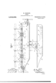
- Figure 1 is an enlarged side elevation of an improved air-shlp showing the ship proper and the car in a parallel position.
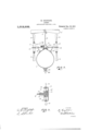
- Fig. 2 is a vertical transverse sectional view of the ship proper taken on the line 22, Fig. 1.
- Fig. 3 is an enlarged vertical sectional view through the center of one of the vertically disposed propellers, showing the means by which the blades are feathered.
- 1 represents a cylindrical vessel forming ,the ship slightly conical, as indicated at 1.
- the rear end has a straight Vertical wall 2', as clearly shown in Fig. 1 of the drawings.
- the conical-shaped forward portion of the ship is for the purpose of reducing the friction of the machine as it passes through the air.
- These motors 2 receive the ower from a pipe 6, communicating with the ship proper and having branch pipes leading to the several motors.
- the blades 4: of the fans 1, are made somewhat crescent-shaped in trans verse cross-section, as shown in Fig. 1, which is essential so as to catch as much air as possible and exert the greatest amount of liftin power when revolved.
- the motors 9 from which the shafts 8 derive their power are supplied with air through a suitable pipe connected to the main pipe 6, and said motors are adapted to revolve the shaft 8 in a clockwise direction.
- the shafts 8 extend out beyond the sides of the ship proper and are supported by suitable brackets 13'. Carried by the bracket 13 is a sleeve 13. upon which is mounted a fixed hub 14. The shaft 8 extends out through the sleeve 13, and through the hub 14, and has mounted thercon the hub rim 1
- This hub rim 11 has a series of propeller blades 10, rotatably mounted therein, the inner ends 12 of said propeller blades are provided with cranks 12 which extend into a spiral groove 15, in the hub 14:. From this description, it will be seen that the sleeve 13 is held against rotation and the rotation of the shaft 8 causes the rim 1 1 to revolve carrying the propeller blades. The propeller blades are caused to oscillate owing to the crank 12', traveling in the groove 15 of the hub 14. The relative arrangement of the hub 1a and the rim 11 is such that the propeller blades feather so that the propellers exert only a lifting power.
- motor driven propeller shaft 15 Pivotally attached to the bow end of the cylinder 1, is the motor driven propeller shaft 15 which motor 15 derives its power from the reservoir 1 through the pipe 6 and passing operates the drawing or sucking propeller 16.
- This shaft 15 with its motor 15 being pivoted at 17 is held in position laterally by suitable steering chains or lines 18 which run through suitable sheaves 19 and 20 mounted upon the side of the cylinder 1 and lead to the operating drum in the car which will be more fully explained later.
- the motor driven propeller shaft 21 which is identical in every respect with that of the bow propelle'nexcept that the blades of the after propeller are arranged to thrust or push instead of pull as in thecase of the bow one, and both of said,propellers unite in propelling and' steering the ship.
- the shaft 21 and its motor are held in position by means of the steering lines 22 pass ing through sheaves 23 and 24 to the operating drum, the steering lines on the opposite side of the ship to that in the drawings through similar sheaves to the opposite side of the steering drum as is c0mmon in such practice.
- the car 25 represents the car, which as before stated, is pivot-ally suspended from the under side of the cylinder at 26 in the bracket 27 securely fastened to the cylinder 1, the car being preferably rectangular in cross section and flat bottomed.
- the forward end of thebottorn of the car is tapered upward and slightly concaved as shown at 30, this being for the purpose of more easily surmounting the air and the lower corner of the stern is preferably slightly rounded.
- the steering wheel 31 mounted upon the shaft 32, which carries the drum 33- around which the steering lines or cables from the bow and stern propellers are wound and operated, which in turn determines the position of the same and guides the ship laterally.
- Suitable cable operated spring valves 38 are interposed between the various motors and the airsupply pipe 6 so that the motors may be governed by the operator from the car 25, and for which purpose the various cables 39 lead through suitable sheaves 40 and down through a verticaltunnel or tube 41, through the cylinder 1 to a set of the air motors which I have illustrated are of the type used for drilling and such work, and I do not wish to limit myself to details in construction, as these will doubtlessvary greatly under different circumstances.
- An air-ship comprising a body portion, a car suspended from the body portion, means within the car supplying the power to the body portion, and propellers carried by the body portion and operated by the power in the body portion.
- An air-ship comprising a body-portion, lifting fans and propeller fans carried by the body-portion, means carried by the body-portion for operating said fans, a source of power carried and driving said fan operating mechanism, a car suspended from the body portion, and means within the car for generating power 'and supplying it to the body-portion.
- An air-ship comprising a body-portion, lifting fans and propelling fans carried by the body-portion, a separate and independent fluid operated motor for each fan and receiving its power from the bodyportion, a car pivotally suspended from the lower end of the body-portion and means carried by the car for supplying the body portion with the necessary fluid.
- An air-ship comprising an elongated body portion, vertically arranged lifting fans, horizontally arranged propelling fans, a separate motor for each fan, a fluid supply pipe connected to the body portion and communicating with each of said motors, a car pivotally suspended fromthe lower end ried by the car for supplying the tion with body porby the body-portion the necessary fluid, andmeans '70 those which give the greatest I carried by the car for operating said compressor.
- An air-shaft comprising a body portion, lifting fans and propelling fans carried thereby, the propeller fans horizontally adjustable, a carpivotally suspended from the lower end of the body portion, a lever within the car for adjusting the relative positions of the car and the body-portion, means within the car for moving said driving fans for steering the machine, and a power generator carried by the car for supplying the body-portion with the necessary power to propel the fans.
- An air-ship of the character described a body-portion, lifting fans and propelling fans carriedby the body-portion, a separate motor for each fan, a supply pipe connected to the body-portion and communi-' eating with the separate motors for driving the fans, a car pivotally suspended by the body portion, a lever for adjusting the relative position ofthe car and body portion, an air-compressor within the car for sup plying the body portion with compressed air, 0
- An air-ship comprising a body-port'on, lifting fans carried thereby, driving fans pivotally supported at the forward and rear ends of the body-portion, a car pivotally suspended from the lower end of the body portion, a link connected to the body portion and to the lever carried by the car, whereby the relative position of the car and body-portion may be changed, cables connected to the driving fansbeyond their pivotal connection with the body-portion and passing over blocks carried by the body'portion and around the drum carried by the car and means for operating said drum whereby the driving fans may be moved horizontally substantially as described.
- An air ship comprising a body-portion, lifting fans carried thereby, driving fans horizontally pivoted at the forward and rear ends of the body portion, a car pivotally suspended from the lower end of the. body portion, means for adjusting the relative position of the car and body-portion, cables secured to the drive fans on the outside of the pivotal'connection with the body portion and passing over blocks carried by the body-portion and around a drum carried by the car, the said cables so wound upon the drum that the ti irningof the drum will throw. the rear fan in one direction and the forward fan in the reverse direction, substantially as described.
- An air ship comprising an elongated body portion vertically arranged lifting fans horizontally arranged propelling fans, motors for said fans, a. fluid supply pipe connected to the body portion and communicating with said motors, a car suspended from the lower end of the body-portion, and means within the car for supplying the body-portion with the necessary fluid.
- An air ship comprising an elongated body-portion, Vertically arranged lifting fans horizontally arranged propelling fans,
- An air ship comprising a body portion, lifting fans and propelling fans carried by the body portion, vertically pivoted steering fans carried by the forward and rear ends of the bod portion, a separate motor for the propelling, lifting and steering fans, a supply pipe connected to the body portion and communicating with the separate motors for driving the fans, a car pivotally suspended by the body portion, a lever for adjusting the relative position of the car and body-portion, an air compressor within the car for supplying the body portion with compressed air, a motor for driving said compressor, and cables secured to the guide fans on the outside of the pivotal connection with the body portion and passing over the blocks carried by the body-portion, a drum carried by the car and around which the cables are wound in opposite directions, whereby the rotation of the drum will throw the rear fan in one direction and the forward fan in the reverse direction, substantially as described.
- An air-ship comprising a body-portion, lifting fans carried by the body portion, propeller fans carried by the body portion, means carried by the body-portion for operating said fans, a source of power carried by the body-portion, a car suspended from the body portion and means within the car for generatingthe power and supplying it to the body portion.
- An air-ship comprising a body portion, a fan carried by the body portion for propelling and lifting the same, means carried by the body portion for operating said fans, a source of power carried by the bodyportion and driving said fan operating mechanism, a car suspended from the bodyportion, means for adjusting the relative position of the car and body portion, and means carried by the car for supplying the body portion with the necessary source of power.
Landscapes
- Engineering & Computer Science (AREA)
- Mechanical Engineering (AREA)
- Aviation & Aerospace Engineering (AREA)
- Structures Of Non-Positive Displacement Pumps (AREA)
Description
M. ENGSTROM.
AIRSHIP.
APPLICATION FILED NOV.1
2 SHEETS-SHEET l.
Patented Dec. 19, 1911.
IN VEN TOR A T TOR/VIE V M. ENGSTROM.
-AIRSHIP.
AIPLIOATION FILED NOV. 1, mm,
1,012,532. Patented Dec.19,1911
2 SHEETS-SHEET 2.
INVENTOR WITN ssss:
UNITED STATES PATENT OFFICE.
MAURITZ ENGSTROM, OF GLAM FALLS, WISCONSIN.
.AIRSHIP.
To all whom it may concern:
Be it known that I, MAURITZ ENGSTROM, a citizen of the United States, residing at Clam Falls, in the county of Polk and State of WVisconsin, have invented certain new and useful Improvements in Airships, of which the following is a specification, reference being had therein to the accompanying drawlng.
This invention relates to improvements in air-ships.
The object of my invent-ion is to provide an air-ship in which the ship proper consists of an elongated cylindrically shaped vessel, being somewhat conical in form and having pivotally suspended from its under side a car for carrying the operator and a mechanism for generating the power.
Another object of my invention is to provide a ship proper with a propelling mechanism, the same being of such a shape as to convey the power fluid by means of which the said propellers are caused to rev lve.
A still further object of my invention is to provide the ship proper at its forward and at its rear ends with a drawing and pushing propeller, each adjustable on a vertical pivot, whereby the ship may be steered.
A still further object of my invention is to provide a ship of-this character having certain details of structure hereinafter more fully set forth.
In the accompanying drawingsFigure 1 is an enlarged side elevation of an improved air-shlp showing the ship proper and the car in a parallel position. Fig. 2 is a vertical transverse sectional view of the ship proper taken on the line 22, Fig. 1. Fig. 3 is an enlarged vertical sectional view through the center of one of the vertically disposed propellers, showing the means by which the blades are feathered.
Referring now tothe drawings, 1 represents a cylindrical vessel forming ,the ship slightly conical, as indicated at 1.
proper and which has its forward end The rear end has a straight Vertical wall 2', as clearly shown in Fig. 1 of the drawings. The conical-shaped forward portion of the ship is for the purpose of reducing the friction of the machine as it passes through the air.
Mounted upon the upper end of the shi proper, are series of motors 2 carrying vertically disposed shafts 3, having at their upper ends the lifting fans 1. I have shown four Specification of Letters Patent.
Application filed November 1, 1910.
Patented Dec. 19, 1911. Serial No. 590,229.
of these lifting fans, but it is understood that any desired number may be used. These motors 2 receive the ower from a pipe 6, communicating with the ship proper and having branch pipes leading to the several motors. The blades 4: of the fans 1, are made somewhat crescent-shaped in trans verse cross-section, as shown in Fig. 1, which is essential so as to catch as much air as possible and exert the greatest amount of liftin power when revolved.
ounted upon the upper end of the ship proper, between the two forward fans and between the two rear fans are two motor propelled shafts 8 carrying a propeller upon each end, and these fans are identical in structure. The motors 9 from which the shafts 8 derive their power are supplied with air through a suitable pipe connected to the main pipe 6, and said motors are adapted to revolve the shaft 8 in a clockwise direction. The shafts 8 extend out beyond the sides of the ship proper and are supported by suitable brackets 13'. Carried by the bracket 13 is a sleeve 13. upon which is mounted a fixed hub 14. The shaft 8 extends out through the sleeve 13, and through the hub 14, and has mounted thercon the hub rim 1|. This hub rim 11 has a series of propeller blades 10, rotatably mounted therein, the inner ends 12 of said propeller blades are provided with cranks 12 which extend into a spiral groove 15, in the hub 14:. From this description, it will be seen that the sleeve 13 is held against rotation and the rotation of the shaft 8 causes the rim 1 1 to revolve carrying the propeller blades. The propeller blades are caused to oscillate owing to the crank 12', traveling in the groove 15 of the hub 14. The relative arrangement of the hub 1a and the rim 11 is such that the propeller blades feather so that the propellers exert only a lifting power. These vertically arranged propellers not only exert a great lifting power, but they are also designed to thoroughly cut up and destroy as much as possible the thrust of the descending air from the vertical lifting fans and thereby prevent the downward draft caused by said fans to unbalance the machine and thus cause a better balanced machine.
Pivotally attached to the bow end of the cylinder 1, is the motor driven propeller shaft 15 which motor 15 derives its power from the reservoir 1 through the pipe 6 and passing operates the drawing or sucking propeller 16. This shaft 15 with its motor 15 being pivoted at 17 is held in position laterally by suitable steering chains or lines 18 which run through suitable sheaves 19 and 20 mounted upon the side of the cylinder 1 and lead to the operating drum in the car which will be more fully explained later.
At the stern of the cylinder 1 is pivoted the motor driven propeller shaft 21, which is identical in every respect with that of the bow propelle'nexcept that the blades of the after propeller are arranged to thrust or push instead of pull as in thecase of the bow one, and both of said,propellers unite in propelling and' steering the ship. The shaft 21 and its motor are held in position by means of the steering lines 22 pass ing through sheaves 23 and 24 to the operating drum, the steering lines on the opposite side of the ship to that in the drawings through similar sheaves to the opposite side of the steering drum as is c0mmon in such practice.
25 represents the car, which as before stated, is pivot-ally suspended from the under side of the cylinder at 26 in the bracket 27 securely fastened to the cylinder 1, the car being preferably rectangular in cross section and flat bottomed.
28 is a tilting rod pivoted in the bracket 27 just above the pivot 26, the opposite ehd of which rod is attached to the quadrant lever 29 in the car, whereby the horizontal position of the car in relation to the locomotive may be readily changed as required in ascending and descending.
The forward end of thebottorn of the car is tapered upward and slightly concaved as shown at 30, this being for the purpose of more easily surmounting the air and the lower corner of the stern is preferably slightly rounded.
Within the car and in any convenient location is the steering wheel 31 mounted upon the shaft 32, which carries the drum 33- around which the steering lines or cables from the bow and stern propellers are wound and operated, which in turn determines the position of the same and guides the ship laterally.
34 represents an electric storage battery which-furnishes power to the electric motor 35, which in turn operates the air compressor 36, whereby compressed air is supplied to the reservoir or cylinder 1, through the flexible pipe 37.
Suitable cable operated spring valves 38 are interposed between the various motors and the airsupply pipe 6 so that the motors may be governed by the operator from the car 25, and for which purpose the various cables 39 lead through suitable sheaves 40 and down through a verticaltunnel or tube 41, through the cylinder 1 to a set of the air motors which I have illustrated are of the type used for drilling and such work, and I do not wish to limit myself to details in construction, as these will doubtlessvary greatly under different circumstances.
Having thus described my invention, what I claim and desire to secure by Letters Patent is:
1. An air-ship comprising a body portion, a car suspended from the body portion, means within the car supplying the power to the body portion, and propellers carried by the body portion and operated by the power in the body portion.
2. An air-ship c'ompr1sing a body-portion, lifting fans and propeller fans carried thereby, means carried by the body-portion for operating said fans, a car pivotally carried by the body portion, and means carried by the car for supplying the body-portion with the power for operating the fans.
3. An air-ship comprising a body-portion, lifting fans and propeller fans carried by the body-portion, means carried by the body-portion for operating said fans, a source of power carried and driving said fan operating mechanism, a car suspended from the body portion, and means within the car for generating power 'and supplying it to the body-portion.
4:. An air-ship comprising a body-portion, lifting fans and propelling fans carried by the body-portion, a separate and independent fluid operated motor for each fan and receiving its power from the bodyportion, a car pivotally suspended from the lower end of the body-portion and means carried by the car for supplying the body portion with the necessary fluid.
5. An air-ship comprising an elongated body portion, vertically arranged lifting fans, horizontally arranged propelling fans, a separate motor for each fan, a fluid supply pipe connected to the body portion and communicating with each of said motors, a car pivotally suspended fromthe lower end ried by the car for supplying the tion with body porby the body-portion the necessary fluid, andmeans '70 those which give the greatest I carried by the car for operating said compressor.
6. An air-shaft comprising a body portion, lifting fans and propelling fans carried thereby, the propeller fans horizontally adjustable, a carpivotally suspended from the lower end of the body portion, a lever within the car for adjusting the relative positions of the car and the body-portion, means within the car for moving said driving fans for steering the machine, and a power generator carried by the car for supplying the body-portion with the necessary power to propel the fans.
7. An air-ship of the character described, a body-portion, lifting fans and propelling fans carriedby the body-portion, a separate motor for each fan, a supply pipe connected to the body-portion and communi-' eating with the separate motors for driving the fans, a car pivotally suspended by the body portion, a lever for adjusting the relative position ofthe car and body portion, an air-compressor within the car for sup plying the body portion with compressed air, 0
storage battery for driving said motor.
8. An air-ship comprising a body-port'on, lifting fans carried thereby, driving fans pivotally supported at the forward and rear ends of the body-portion, a car pivotally suspended from the lower end of the body portion, a link connected to the body portion and to the lever carried by the car, whereby the relative position of the car and body-portion may be changed, cables connected to the driving fansbeyond their pivotal connection with the body-portion and passing over blocks carried by the body'portion and around the drum carried by the car and means for operating said drum whereby the driving fans may be moved horizontally substantially as described.
9. An air ship comprising a body-portion, lifting fans carried thereby, driving fans horizontally pivoted at the forward and rear ends of the body portion, a car pivotally suspended from the lower end of the. body portion, means for adjusting the relative position of the car and body-portion, cables secured to the drive fans on the outside of the pivotal'connection with the body portion and passing over blocks carried by the body-portion and around a drum carried by the car, the said cables so wound upon the drum that the ti irningof the drum will throw. the rear fan in one direction and the forward fan in the reverse direction, substantially as described.
10. An air ship comprising an elongated body portion vertically arranged lifting fans horizontally arranged propelling fans, motors for said fans, a. fluid supply pipe connected to the body portion and communicating with said motors, a car suspended from the lower end of the body-portion, and means within the car for supplying the body-portion with the necessary fluid.
11. An air ship comprising an elongated body-portion, Vertically arranged lifting fans horizontally arranged propelling fans,
a motor for driving said compressor and] a separate motor for each fan, a fluid supply pipe connected to the body-portion and communicating with each of said motors, a car pivotally suspended from the lower end of the body-portion, a link connecting said body-portion and a lever carried by the car, an air compressor carried by the car and having a flexible pipe connecting it with the body portion, and means carried by the car for operating said compressor.
. 12. An air ship, comprising a body portion, lifting fans and propelling fans carried by the body portion, vertically pivoted steering fans carried by the forward and rear ends of the bod portion, a separate motor for the propelling, lifting and steering fans, a supply pipe connected to the body portion and communicating with the separate motors for driving the fans, a car pivotally suspended by the body portion, a lever for adjusting the relative position of the car and body-portion, an air compressor within the car for supplying the body portion with compressed air, a motor for driving said compressor, and cables secured to the guide fans on the outside of the pivotal connection with the body portion and passing over the blocks carried by the body-portion, a drum carried by the car and around which the cables are wound in opposite directions, whereby the rotation of the drum will throw the rear fan in one direction and the forward fan in the reverse direction, substantially as described.
, 13. An air-ship comprising a body-portion, lifting fans carried by the body portion, propeller fans carried by the body portion, means carried by the body-portion for operating said fans, a source of power carried by the body-portion, a car suspended from the body portion and means within the car for generatingthe power and supplying it to the body portion.
14:. An air-ship comprising a body portion, a fan carried by the body portion for propelling and lifting the same, means carried by the body portion for operating said fans, a source of power carried by the bodyportion and driving said fan operating mechanism, a car suspended from the bodyportion, means for adjusting the relative position of the car and body portion, and means carried by the car for supplying the body portion with the necessary source of power.
In testimony whereof I hereunto affix my signature in the presence of two witnesses.
MAURITZ ENG STROM.
Witnesses:
DANIEL JOHNSON, CONSTANCE DANIELS.
Priority Applications (1)
| Application Number | Priority Date | Filing Date | Title |
|---|---|---|---|
| US59022910A US1012532A (en) | 1910-11-01 | 1910-11-01 | Airship. |
Applications Claiming Priority (1)
| Application Number | Priority Date | Filing Date | Title |
|---|---|---|---|
| US59022910A US1012532A (en) | 1910-11-01 | 1910-11-01 | Airship. |
Publications (1)
| Publication Number | Publication Date |
|---|---|
| US1012532A true US1012532A (en) | 1911-12-19 |
Family
ID=3080840
Family Applications (1)
| Application Number | Title | Priority Date | Filing Date |
|---|---|---|---|
| US59022910A Expired - Lifetime US1012532A (en) | 1910-11-01 | 1910-11-01 | Airship. |
Country Status (1)
| Country | Link |
|---|---|
| US (1) | US1012532A (en) |
Cited By (1)
| Publication number | Priority date | Publication date | Assignee | Title |
|---|---|---|---|---|
| US3253806A (en) * | 1964-05-20 | 1966-05-31 | Eickmann Karl | Control means in a hydraulic driven helicopter |
-
1910
- 1910-11-01 US US59022910A patent/US1012532A/en not_active Expired - Lifetime
Cited By (1)
| Publication number | Priority date | Publication date | Assignee | Title |
|---|---|---|---|---|
| US3253806A (en) * | 1964-05-20 | 1966-05-31 | Eickmann Karl | Control means in a hydraulic driven helicopter |
Similar Documents
| Publication | Publication Date | Title |
|---|---|---|
| US1012532A (en) | Airship. | |
| US899350A (en) | Dirigible flying-machine. | |
| US1237318A (en) | Airship. | |
| US2552008A (en) | Jet-powered rotor system for helicopters | |
| US998553A (en) | Flying-machine. | |
| US1006967A (en) | Propelling mechanism for aerodromes. | |
| US1026959A (en) | Airship. | |
| US462612A (en) | Air-ship | |
| US1087946A (en) | Flying-machine. | |
| US659122A (en) | Apparatus for improving and preserving channels of steams. | |
| US1222674A (en) | Hydroplane. | |
| US1500572A (en) | Helicopter | |
| US1812627A (en) | Trihydro dirigible and airplane | |
| US1598554A (en) | Flying machine | |
| US762273A (en) | Air-ship. | |
| US914969A (en) | Aeroplane. | |
| US1006734A (en) | Dirigible airship. | |
| US1217828A (en) | Hydroplane. | |
| US826052A (en) | Air-ship. | |
| US945514A (en) | Aerial machine. | |
| US1099827A (en) | Airship. | |
| US1015656A (en) | Flying-machine. | |
| US962964A (en) | Airship. | |
| US1011256A (en) | Airship. | |
| US712689A (en) | Air ship or vessel. |