US1011836A - Orthopter. - Google Patents
Orthopter. Download PDFInfo
- Publication number
- US1011836A US1011836A US56123310A US1910561233A US1011836A US 1011836 A US1011836 A US 1011836A US 56123310 A US56123310 A US 56123310A US 1910561233 A US1910561233 A US 1910561233A US 1011836 A US1011836 A US 1011836A
- Authority
- US
- United States
- Prior art keywords
- planes
- machine
- wings
- hull
- vane
- Prior art date
- Legal status (The legal status is an assumption and is not a legal conclusion. Google has not performed a legal analysis and makes no representation as to the accuracy of the status listed.)
- Expired - Lifetime
Links
- 230000033001 locomotion Effects 0.000 description 27
- 210000003414 extremity Anatomy 0.000 description 12
- 230000003028 elevating effect Effects 0.000 description 11
- 230000007246 mechanism Effects 0.000 description 7
- 238000010276 construction Methods 0.000 description 4
- 230000000630 rising effect Effects 0.000 description 4
- 230000000694 effects Effects 0.000 description 3
- 230000009471 action Effects 0.000 description 2
- 230000001965 increasing effect Effects 0.000 description 2
- 208000027418 Wounds and injury Diseases 0.000 description 1
- 230000002159 abnormal effect Effects 0.000 description 1
- 230000001174 ascending effect Effects 0.000 description 1
- 230000008901 benefit Effects 0.000 description 1
- 230000008859 change Effects 0.000 description 1
- 230000002301 combined effect Effects 0.000 description 1
- 230000006378 damage Effects 0.000 description 1
- 230000002939 deleterious effect Effects 0.000 description 1
- 230000000994 depressogenic effect Effects 0.000 description 1
- 238000007598 dipping method Methods 0.000 description 1
- 230000005484 gravity Effects 0.000 description 1
- 230000001771 impaired effect Effects 0.000 description 1
- 208000014674 injury Diseases 0.000 description 1
- 230000001788 irregular Effects 0.000 description 1
- 230000003387 muscular Effects 0.000 description 1
- 230000008520 organization Effects 0.000 description 1
- 230000035939 shock Effects 0.000 description 1
- 230000000153 supplemental effect Effects 0.000 description 1
- 210000001364 upper extremity Anatomy 0.000 description 1
- 238000004804 winding Methods 0.000 description 1
Images


Classifications
-
- B—PERFORMING OPERATIONS; TRANSPORTING
- B64—AIRCRAFT; AVIATION; COSMONAUTICS
- B64C—AEROPLANES; HELICOPTERS
- B64C33/00—Ornithopters
Definitions
- This invention relates to orthopters and has been devised to mechanically reproduce the actions of a bird during flight and under varying conditions of the wind and also to simulate the movements of a bird in rising from and descending toward and alighting upon the surface of the earth.
- the invention consists in the construction and arrangement of the several parts which will be more fully hereinafter specified.
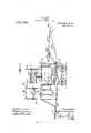
- Figure 1 is a perspective view of an orthopter embodying the fea tures of the invention.
- Fig. 2 is a side elevation of the same showing a portion in dotted lines to illustrate the operation there of.
- Fig. 3 is a transverse vertical section through a portion of the machine.
- Figs. 4 and 5 are detail views illustrating the pullcord cooperating with the several movable parts.
- Fig. 6 is a perspective view of the tail or tail vane serving also as a rudder, partially broken away, and illustrating the operating mechanism and supporting means therefor.
- Fig. 7 is a top plan view of the tail or tail vane and cooperating mechanism.
- Fig. 8 is a longitudinal vertical section through the mechanism for the tail vane, the latter being illustrated in edge elevation.
- Fig. 9 is a transverse vertical section through a port-ion of the tail or tail vane operating means and supporting frame, and showing the mechanism including the tail or tail vane respectively in full lines and in dotted lines in two positions
- the numeral 5 designates a body or hull having ground wheels 6 connected to the bottom thereof by suitable means for engagement with the ground surface to facilitate movement of the entire orthopter pre liminarily to making an ascension and also after descension or return of the machine to the ground surface.
- the body or hull 5 has a front wedge-shaped extremity or prow 7 to cleave the air during movement of he machine, and the dimensions of the body or hull are such as to permit instalment therein of the motive means, which may be of any preferred type and has a carrying inclosure for the operator to occupy a po- Specification of Letters Patent.
- extremity or prow 7 is equipped with transparent doors 8 and sight openings or w1ndows 9 to give the operator a full view in advance of the machine from either side of the prow, the doors and sight openings or windows being duplicated on opposite sides of the prow.
- a wing driving or actuating medium 12 is arranged and consists of a'disk or pulley which is actuated from a transmitting pulley 13 within the upper portion of the body or hull 5 directly operated through the medium of a belt 14 from the motive means.
- a transmitting belt 15 Between the pulleys 12 and 13 is a transmitting belt 15, see Fig. 3, and the pulley 12 is keyed on a shaft 16 carrying cranks 17 and 18 having arms 19 and 20 respectively connected thereto and extending outwardly through slots 21 in the opposite sides of the rear portion'of the auxiliary inclosure 10.
- the operating and controlling elements of the orthopter are equally disposed to balance the machine, and these will now be particularly described.
- a light framework 22 projects forwardly from the body or hull 5 a suitable distance in advance of the front terminal or edge of the prow 7, and supported by this framework in substantially horizontal position is a front balancing plane 23 which is held in fixed position and has a slight upward inclination, as clearly shown by Fig. 2, to as sist in lifting the machine and also to prevent dipping or downward plunging as the machine is propelled through the air.
- This plane 23 is in line with the lower or bottom portion of the body or hull 5 and in conjunction with laterally projecting devices, which will be presently explained, operates to a large extent in maintaining the equilibrium of the machine.
- each frame 24 an elevating and descending rudder 27 is mounted and consists of a plane eccentrically fulcrumed at its inner and outer edges to portions of the frame 24 and provided also at the outer and inner edges with upwardly projecting arms 28 and 29 which are suitably braced to give thesame ample rigidity for operating the rudder or plane.
- Each rudder or plane 27 has a normal upward inclination toward the front of the machine to facilitate rising movement or ascension, and both rudders or planes are connected for simultaneous operation through the medium of cords 30 and 31 secured to the upper and lower ends of the inner arms 28, the two sets of cords 30 and 31 extending inwardly through the sides of the body or hull 5 over suitably positioned pulleys 32 and 33, see Fig.5, and connected to a rocking lever 34 fixed on a shaft 35 mounted in a standard 36 within the body or hull 5 and within easy reaching distance of the operator.
- the shaft 35 is operated through the medium of a crank handle or foot-bar 37 and the said shaft also has thereon a locking disk or ratchet wheel 38 which is engaged by a dog or analogous locking device 39 for holding the planes or rudders 27 in desired adjusted position for any length of time found necessary.
- a locking disk or ratchet wheel 38 Movably suspended from the upper portions of the uprights 25 adjacent to the rudders or planes 27 are automatically operating planes 40, one on each side of the machine, the said planes 40 serving to defleet heavy cross or lateral wind downwardly through the open planes and also upwardly from the latter, rudders or panels 27.
- the planes 40 are free to swing between the up rights 25 and will operate to perform their functions without manual attention or control.
- a frame 41 fixed on the top of the auxiliary inclosure 10 and the rear portion of the deck or top of the body or hull 5 are wings 42 which mechanically simulate the wings of a bird and have side members 43 suitably connected by cross end members 44 of light material.
- the members 43 and 44 and extending transversely of the wings is a plurality of overlapping eccentrically fulcrumed slats or planes 45 from each of which an arm 46 projects upwardly, all of the arms being located at the rear ends of the slats.
- a cord or wire 47 is secured and extends inwardly to the side edge of the top of the frame 41 close to the point where the wing is fulcrumed and is trained over a direction pulley 48. From the direction pulleys 48 the cords 47 extend downwardly through the top or deck of the body or hull 5 and engage direction pulleys 49 within the latter and are terminally secured to levers 5O fulcrumed against the opposite sides of the body or hull 5 and projecting inwardly and terminating in handles or grips 51.
- Each lever 50 has a shoulder 52 which is adapted to be engaged by the upper shouldered end of a latch 53 intermediately pivoted on the inner end of an arm 54 also secured to and projecting inwardly from the same side of the body or hull.
- the latch 53 is held in normal locking position by a spring 55 connected to the same and the adjacent side of the body or hull, all as clearly shown by Fig. 3.
- Adjacent to the top of the frame and forming part of each wing is a pocket 56 which corresponds to the concave or hollow of the birds wing adjacent to the joint of the latter, said pocket having a closed top 57 flanged sides 58 and an outer depending or downwardly inclined extremity 59.
- Each wing also has intermediate pairs of fixed arms 60 extending above and below the same and suitably braced to the side members 43, the lower ends of the pairs of arms being connected by tie rods 61 to which the crank arms 19 are cent-rally attached, as clearly shown by Fig. 1.
- the wings are regularly oscillated or given a flapping movement through the medium of the cranks 17 and arms 19, both arms working in unison or uniformly rising and falling together.
- each deflecting plane 40 Projecting upwardly from the rear end of each deflecting plane 40 is an arm 62 having a cord 63 secured to the upper end thereof and extending inwardly through the adjacent side of the body or hull 5 over direction pulleys 64 and downwardly to the arm 54 where it passes over another direction pulley 65 and then extends inwardly and is attached to the lower end of the latch. 53.
- the main balancing or equilibrium preserving devices are located above the prow 7 of the body or hull 5 in advance of the wings 42.
- a fixed frame 66 is secured to and projects above the top of the prow 7 and thereon is movably mounted a hood 67 comprising opposite downwardly sloped top planes 68, a rear flexible plane or tail 69, supporting outer end posts 70 and central arms 71.
- the posts and arms are connected to laterally projecting frames 72 and the latter with the hood structure as just specified is fulcrumed by a rod 73 in the upper ends of the frames 66, the arms 71 projecting below the rod 7 3 and suitably braced by wires 74 to the frames 72, as clearly shown by Fig. 1.
- the frames 72 carry at their outer ends balancing planes 75 similar in construction to the planes 27 but without positive operating means, the planes 75 being eccent-rically fulcrumed in the frames and normally depressed rearwardly or having a forward and upward inclination.
- the planes 75 freely move between opposing stops 76 at the inner and outer portions of the frames 72 inclosing the said planes 75.
- On the rear sides of the frames 72 adjacent to the planes 75 are downwardly sloping flexible planes 77 which assist in the balancing operation.
- This balancing organization as a whole is operated by pull-cords 78 secured to the sides of the frames 72 and passing downwardly into the interior of the body or hull 5 over direction pulleys 79 and con nected to a suitable operating means, as shown by Fig. 4, which as illustrated consists of an upright shaft 80 having a top winding drum 81 and a hand-wheel 82.
- This operating means may be the same as that shown by Fig. 5 for operating the planes 27 or be controlled by the feet of the operator, and likewise the mechanism shown by Fig. 5 may be replaced by the hand-controlled shaft 80 as shown by Fig. 4.
- the operating mechanism for the several parts within the body or hull 5 is not limited to any precise construction and any suitable devices may be employed which are found to be most effective and convenient.
- the balancing means including the hood may be shifted on its fulcrum and the hood planes 68 as well as the planes 75 have a slight upward inclination to facilitate rising movement of the machine.
- the hood swings later ally on its horizontal axis, and what air may be held therein is liberated or permitted to escape from the under side thereof, and the machine as an entirety may be easily maintained in equilibriumand restored to proper position by the actuation of the said hood or balancing means in the event that it becomes slightly canted.
- propeller shafts 85 are supported in the rear of the planes or panels 27 and planes 40 and are operated by belts 86 from the motive means within the body or hull 5.
- propeller shafts 87 On the rear ends of the propeller shafts are suitable propellers 87, there being one propeller on each side of the machine.
- the propellers are free to operate without liability of contact-ing with any parts in advance of the same, and through one form of propeller has been shown it will be understood that propellers best adapted for the machine will be adopted.
- a longitudinal arm 88 Projecting rearwardly from the body or hull 5 between the propellers 87 is a longitudinal arm 88 having a frame 89 fixed to the rear end thereof, see Figs. 6, 7 8 and 9, the frame being of open structure and of curved contour and provided with a lower track or slide surface 90 and upper inwardly projecting arms 91 terminating in forward angular projections or stops 92. Extending rearwardly from the arms 91 at points intermediate of the latter are guide arms 93 for a purpose which will be presently explained.
- a tiller 94 is centrally fulcrumed on the said latter arm and to the opposite ends thereof steering cords 95 are secured and run into the rear portion of the body or hull 5 and forwardly into the latter to a point within easy reaching distance of the operator.
- the tiller 94 is a part of a swinging frame embodying a central rearwardly projecting bar 96 preferably constructed integral with the tiller and braces 97 connected to the tiller on opposite sides of the fulcrum point of the latter and to the rear extremity of the said bar.
- the rear extremity of the bar 96 has contact with and moves on the track or slide surface 90 of the frame 89, and fixed thereon are bearings 97 in which a tail vane spindle 98 is rotatably mounted and free to throwing the machine.
- the rear extremity 101 of said vane has a normal downward deflection and is flexible to permit the air to pass from under the same with facility and without liability ofinjuring the said vane.
- the rear portion of the vane may be flexed as found necessary by a pull-cord extending therefrom as at 102 forwardly into the lower portion of the body or hull 5, and.
- a trip head or turning segment 103 is fixed and is adapted to contact with either of the projections 92 at the inner terminals of the arms 91, the opposite side edges of the head 103 being inclined in such direction as to effectively move or ride over the said projections 92.
- the stem 99 of the vane 100 has a restricting means secured to the under side thereof to insure a regular and positive movement of the vane, and said restricting means as shown consists of a bar 10% with upper concave edges 105 adapted to contact with the under portions of the guide arms 93.
- the bar 104 extends equal distances on opposite sides of the stem 99, and when the steering frame including the tiller 94: is shifted either to one side or the other of the center of the arm 88 far enough to bring either inclined side edge of the head 103 in engagement with either of the projections 92, the combined tail vane and rudder 100 is tilted at an angle in accordance with the direction of lateral movement thereof, and the restricting means or the portion of the bar 10% nearest the guide arm 93 on the side toward which the tail vane is moved bears against said guide arm and prevents a sudden or loose movement of the tail vane with the result.
- the machine may be gradually steered either to the right or left without liability of abnormally canting or over- ⁇ Vhen the tail vane is returned to its normal horizontal position the movement thereof is also rendered regular and without looseness through the medium of the guide arms 93 and restrictive means just explained.
- the gradual change of the tail vane from a horizontal position to an angular position will be found exceptionally advantageous in controlling the direction of movement of the machine, not only when making turns to the right or left in a horizontal plane, but also in turning during ascension or descension of the machine.
- All of the parts of the machine will be constructed of light material and thoroughly braced to render them strong and durable.
- the inclosed body or hull 5 will protect the operator against cold and strong winds and also provide effective means for shielding the operating devices including the motive means from deleterious effects of moisture that may be encountered in high elevations as well as during storms.
- One of the very effective features of the present machine is the construction of the wings with movable members or planes which open and present only the upper edges thereof to the air on their upward strokes and thereby reduce the resistance, but close on their down strokes and so have greater efficiency in increasing the ascend ing movement of the machine, and the efficiency is further increased by the fact that the wings are curved downwardly toward their outer ends or tips and thus compress and retain a vast amount of air thereunder and create a greater lifting power than if the wings were flat.
- each wing acts as an air chamber, and when the prow of the machine plows through the air it will displace a volume of air equal to the body of the machine, and owing to the very elastic characteristic of the air it will when thus disturbed immediately ascend in currents and be caught in the pockets of the wings, where there will be a tendency to compress it, and an outward movement in an upward direction of the air thus collected at right angles to the line of flight will ensue.
- the air thus gathered in the pockets will create'an upward pushing action similar to the muscular push exercised by a bird in soaring.
- the air swell created by the moving body of the machine tends to move backward, but owing to the operation just explained and the shape of the wings will result in a movement of the air toward the free ends of the wings.
- the downward movement of the wings compresses the air and releases it in such manner that it serves as a cushion of compressed air, with material advantage in driving the machine with the least expenditure of power.
- the forward lifting vane 23 and rear combined tail and rudder 100 unitedly operate to keep the machine in balance and prevent forward and rear plunging.
- the wings operate in conjunction with the forward plane 23 and combined tail vane and rudder to prevent pitching of the machine, and these parts together with the side planes or panels 27 and 7 5 at all times effect a uniformity of position or obstruct any material abnormal canting, or tilting of the machine toward one side or the other, irrespective of the character of the wind as to force and direction, and, furthermore, it will be seen that at points where the air is released from under the several planes, such release is gradual by reason of the flexibility of the auxiliary planes which have a downward slope.
- the wings may be brought to a standstill, or remain immovable by disconnecting the belt or driving means for the arms 19 and disk 12 from the motive means, and under such condition the power of the motive means will be concentrated on the propellers 87 to drive the machine forwardly.
- the wings may be actuated manually from the interior of the body 5 to control the machine, particularly in descent and effect a gradual alight ing without injury to the several parts or the operator. It is preferred that the wheels 3 have a yielding movement so as to take up any shock or jar when alighting.
- the machine is so constructed as to accommodate different conditions of air as regards density and counter-currents in various localities and as modified by surface condi tions of the earth and it is intended to modify the proportions and dimensions of the several parts in such manner as to obtain the best results under different conditions of air pressure in different climates or localities.
- the combination with a body having a motive means therein, of a series of planes at the front, rear and opposite sides of the body, and flapping wings disposed above the body over the side planes and operative from the interior of the latter by the motive means, the wings being composed of a plurality of slats having their opposite ends eccentrically fulcrumed and their side edges free for overlapping engagement, the slats having an automatically opening and closing operation.
- the combination wit-h a body having propelling means, of movable elevating wings having automatically opening and closing planes, planes at opposite sides of the body below the wings, vertically disposed swinging planes adjacent to the said planes at opposite sides of the body, and connecting means between the said vertically disposed swinging planes and the opening and closing planes of the wings for automatically opening the latter when the said swinging planes are forcefully moved by lateral currents of air toward the sides of the body.
- the combination with propelling means of a plurality of planes including automatically movable side planes or rudders to assist in the elevation and descent of the machine, swinging suspended planes adjacent to the side planes or rudders to deflect countercurrents, flapping wings over the side planes or rudders and including movable planes, and a laterally shiftable flat tail vane to serve as a rear rudder and also provided with means for causing it to assume reverse angles of inclination to balance the machine.
Landscapes
- Engineering & Computer Science (AREA)
- Aviation & Aerospace Engineering (AREA)
- Wind Motors (AREA)
Description
' J. O'LEAR Y.
ORTHOPTER.
APPLIUATION FILED MAY 13, 1910. 1,01 1,836. Patented Dec.12,1-9 11.
m I (as 1%7z0 ear wgm J. OLEARY. ORTHOPTER.
APPLICATION FILED MAY 13, 1910.
Patented Dec. 12, 1911.
4 SHEETS-SHEET 2.
NwN
NQW
J. OLEARY.
ORTHOPTER.
APPLICATION F ILED MAY 13, 1910. 1,01 1,836. Patented Dec.12,1911.
' 4 SHEETS-SHEET 3. 6,
4a J7 J6 W OLUMIHA ILANUGRAPH |:o., WASHINGTON. D, c.
J. OLEARY.
ORTHOPTER. APPLICATION FILED MAY 13, 1910.
1,01 1,836. Patented Dec. 12, 1911.
4 SHEETS-SHEET 4. I
TED STATES PATENT OFFICE.
JOHN OLEARY, OF COI-IOES, NEW YORK.
ORTHOPTER.
T all whom it may concern;
Be it known that I, JOHN OLEARY, a citizen of the United States, residing at Cohces, in the county of Albany and State of New York, have invented new and useful Improvements in Orthopters, of which the following is a specification.
This invention relates to orthopters and has been devised to mechanically reproduce the actions of a bird during flight and under varying conditions of the wind and also to simulate the movements of a bird in rising from and descending toward and alighting upon the surface of the earth.
The invention consists in the construction and arrangement of the several parts which will be more fully hereinafter specified.
In the drawings: Figure 1 is a perspective view of an orthopter embodying the fea tures of the invention. Fig. 2 is a side elevation of the same showing a portion in dotted lines to illustrate the operation there of. Fig. 3 is a transverse vertical section through a portion of the machine. Figs. 4 and 5 are detail views illustrating the pullcord cooperating with the several movable parts. Fig. 6 is a perspective view of the tail or tail vane serving also as a rudder, partially broken away, and illustrating the operating mechanism and supporting means therefor. Fig. 7 is a top plan view of the tail or tail vane and cooperating mechanism. Fig. 8 is a longitudinal vertical section through the mechanism for the tail vane, the latter being illustrated in edge elevation. Fig. 9 is a transverse vertical section through a port-ion of the tail or tail vane operating means and supporting frame, and showing the mechanism including the tail or tail vane respectively in full lines and in dotted lines in two positions.
The numeral 5 designates a body or hull having ground wheels 6 connected to the bottom thereof by suitable means for engagement with the ground surface to facilitate movement of the entire orthopter pre liminarily to making an ascension and also after descension or return of the machine to the ground surface. The body or hull 5 has a front wedge-shaped extremity or prow 7 to cleave the air during movement of he machine, and the dimensions of the body or hull are such as to permit instalment therein of the motive means, which may be of any preferred type and has a carrying inclosure for the operator to occupy a po- Specification of Letters Patent.
Application filed May 13, 1910.
Patented Dec. 12, 1911.
Serial No. 561,233.
extremity or prow 7 is equipped with transparent doors 8 and sight openings or w1ndows 9 to give the operator a full view in advance of the machine from either side of the prow, the doors and sight openings or windows being duplicated on opposite sides of the prow. On the top of the body or hull 5, which constitutes a deck, an auxiliary inclosure 10 is arranged and also has a wedge-shaped front extremity 11. In this auxiliary inclosure a wing driving or actuating medium 12 is arranged and consists of a'disk or pulley which is actuated from a transmitting pulley 13 within the upper portion of the body or hull 5 directly operated through the medium of a belt 14 from the motive means. Between the pulleys 12 and 13 is a transmitting belt 15, see Fig. 3, and the pulley 12 is keyed on a shaft 16 carrying cranks 17 and 18 having arms 19 and 20 respectively connected thereto and extending outwardly through slots 21 in the opposite sides of the rear portion'of the auxiliary inclosure 10. Around the body or hull 5 and supplemental inclosure 10 the operating and controlling elements of the orthopter are equally disposed to balance the machine, and these will now be particularly described.
A light framework 22 projects forwardly from the body or hull 5 a suitable distance in advance of the front terminal or edge of the prow 7, and supported by this framework in substantially horizontal position is a front balancing plane 23 which is held in fixed position and has a slight upward inclination, as clearly shown by Fig. 2, to as sist in lifting the machine and also to prevent dipping or downward plunging as the machine is propelled through the air. This plane 23 is in line with the lower or bottom portion of the body or hull 5 and in conjunction with laterally projecting devices, which will be presently explained, operates to a large extent in maintaining the equilibrium of the machine. Projecting outwardly from opposite sides of the lower portion of the body or hull 5 are light open frames 24, one on each side, and provided with uprights 25 at their outer extremities intersecting horizontal braces 26 which run inwardly to the upper portion of the adjacent side of the said body or hull. lVithin each frame 24 an elevating and descending rudder 27 is mounted and consists of a plane eccentrically fulcrumed at its inner and outer edges to portions of the frame 24 and provided also at the outer and inner edges with upwardly projecting arms 28 and 29 which are suitably braced to give thesame ample rigidity for operating the rudder or plane. Each rudder or plane 27 has a normal upward inclination toward the front of the machine to facilitate rising movement or ascension, and both rudders or planes are connected for simultaneous operation through the medium of cords 30 and 31 secured to the upper and lower ends of the inner arms 28, the two sets of cords 30 and 31 extending inwardly through the sides of the body or hull 5 over suitably positioned pulleys 32 and 33, see Fig.5, and connected to a rocking lever 34 fixed on a shaft 35 mounted in a standard 36 within the body or hull 5 and within easy reaching distance of the operator. The shaft 35 is operated through the medium of a crank handle or foot-bar 37 and the said shaft also has thereon a locking disk or ratchet wheel 38 which is engaged by a dog or analogous locking device 39 for holding the planes or rudders 27 in desired adjusted position for any length of time found necessary. Movably suspended from the upper portions of the uprights 25 adjacent to the rudders or planes 27 are automatically operating planes 40, one on each side of the machine, the said planes 40 serving to defleet heavy cross or lateral wind downwardly through the open planes and also upwardly from the latter, rudders or panels 27. The planes 40 are free to swing between the up rights 25 and will operate to perform their functions without manual attention or control.
Extending outwardly from opposite sides of a frame 41 fixed on the top of the auxiliary inclosure 10 and the rear portion of the deck or top of the body or hull 5 are wings 42 which mechanically simulate the wings of a bird and have side members 43 suitably connected by cross end members 44 of light material. \Vithin the members 43 and 44 and extending transversely of the wings is a plurality of overlapping eccentrically fulcrumed slats or planes 45 from each of which an arm 46 projects upwardly, all of the arms being located at the rear ends of the slats. To the upper ends of the arms of each wing a cord or wire 47 is secured and extends inwardly to the side edge of the top of the frame 41 close to the point where the wing is fulcrumed and is trained over a direction pulley 48. From the direction pulleys 48 the cords 47 extend downwardly through the top or deck of the body or hull 5 and engage direction pulleys 49 within the latter and are terminally secured to levers 5O fulcrumed against the opposite sides of the body or hull 5 and projecting inwardly and terminating in handles or grips 51. Each lever 50 has a shoulder 52 which is adapted to be engaged by the upper shouldered end of a latch 53 intermediately pivoted on the inner end of an arm 54 also secured to and projecting inwardly from the same side of the body or hull. The latch 53 is held in normal locking position by a spring 55 connected to the same and the adjacent side of the body or hull, all as clearly shown by Fig. 3. Adjacent to the top of the frame and forming part of each wing is a pocket 56 which corresponds to the concave or hollow of the birds wing adjacent to the joint of the latter, said pocket having a closed top 57 flanged sides 58 and an outer depending or downwardly inclined extremity 59. The outer downwardly inclined or sloping extension 59 and the side flanges, together with the top, have sufficient flexibility to render the same effective, and the air is crowded thereunder and creates a great lifting power by the operation of the wings. Each wing also has intermediate pairs of fixed arms 60 extending above and below the same and suitably braced to the side members 43, the lower ends of the pairs of arms being connected by tie rods 61 to which the crank arms 19 are cent-rally attached, as clearly shown by Fig. 1. The wings are regularly oscillated or given a flapping movement through the medium of the cranks 17 and arms 19, both arms working in unison or uniformly rising and falling together.
When normally working the flapping of the wings causes the slats 45 to close during the downward movement of the wings owing to the pressure of the air against said slats and the eccentric disposition of their fulcrums, and during upward movement of the wings the slats open and permit the air to pass therethrough and thereby avoid retardation of the operation of the wings in their ascent.
Projecting upwardly from the rear end of each deflecting plane 40 is an arm 62 having a cord 63 secured to the upper end thereof and extending inwardly through the adjacent side of the body or hull 5 over direction pulleys 64 and downwardly to the arm 54 where it passes over another direction pulley 65 and then extends inwardly and is attached to the lower end of the latch. 53. It will be understood that this arrangement in connection with the controlling means for the movable planes of the wings is duplicated on each side of the machine, and when the planes 40 are forced inwardly by heavy lateral or cross winds the latches 53 are released from the levers 50 by the pull exerted on the cords 63 and the overlapping planes 45 of the wings, which may at the time be closed, automatically open owing to their eccentric mounting and the heavy currents which are deflected downwardly against the side rudders, planes or panels 27 are thrown upwardly in part and pass through the open wings and thereby avoid interference with the operation of said wings or an irregular movement or unbalancing of the machine. By this means the equilibrium of the machine may be maintained irrespective of heavy winds striking the same at opposite sides.
The main balancing or equilibrium preserving devices are located above the prow 7 of the body or hull 5 in advance of the wings 42. A fixed frame 66 is secured to and projects above the top of the prow 7 and thereon is movably mounted a hood 67 comprising opposite downwardly sloped top planes 68, a rear flexible plane or tail 69, supporting outer end posts 70 and central arms 71. The posts and arms are connected to laterally projecting frames 72 and the latter with the hood structure as just specified is fulcrumed by a rod 73 in the upper ends of the frames 66, the arms 71 projecting below the rod 7 3 and suitably braced by wires 74 to the frames 72, as clearly shown by Fig. 1. The frames 72 carry at their outer ends balancing planes 75 similar in construction to the planes 27 but without positive operating means, the planes 75 being eccent-rically fulcrumed in the frames and normally depressed rearwardly or having a forward and upward inclination. The planes 75 freely move between opposing stops 76 at the inner and outer portions of the frames 72 inclosing the said planes 75. On the rear sides of the frames 72 adjacent to the planes 75 are downwardly sloping flexible planes 77 which assist in the balancing operation. This balancing organization as a whole is operated by pull-cords 78 secured to the sides of the frames 72 and passing downwardly into the interior of the body or hull 5 over direction pulleys 79 and con nected to a suitable operating means, as shown by Fig. 4, which as illustrated consists of an upright shaft 80 having a top winding drum 81 and a hand-wheel 82. This operating means, however, may be the same as that shown by Fig. 5 for operating the planes 27 or be controlled by the feet of the operator, and likewise the mechanism shown by Fig. 5 may be replaced by the hand-controlled shaft 80 as shown by Fig. 4. The operating mechanism for the several parts within the body or hull 5 is not limited to any precise construction and any suitable devices may be employed which are found to be most effective and convenient. At any time desired through the mechanism specified the balancing means including the hood may be shifted on its fulcrum and the hood planes 68 as well as the planes 75 have a slight upward inclination to facilitate rising movement of the machine. As the hood swings later ally on its horizontal axis, and what air may be held therein is liberated or permitted to escape from the under side thereof, and the machine as an entirety may be easily maintained in equilibriumand restored to proper position by the actuation of the said hood or balancing means in the event that it becomes slightly canted.
Around the outer sides and rear ends of the frames 24 are downwardly sloping narrow flexible planes 83 which assist in lifting the machine, and at all points that may be found necessary or desirable these small planes will be applied to increase the air contacting surface of the machine as an entirety.
In suitable frames 84 propeller shafts 85 are supported in the rear of the planes or panels 27 and planes 40 and are operated by belts 86 from the motive means within the body or hull 5. On the rear ends of the propeller shafts are suitable propellers 87, there being one propeller on each side of the machine. The propellers are free to operate without liability of contact-ing with any parts in advance of the same, and through one form of propeller has been shown it will be understood that propellers best adapted for the machine will be adopted.
Projecting rearwardly from the body or hull 5 between the propellers 87 is a longitudinal arm 88 having a frame 89 fixed to the rear end thereof, see Figs. 6, 7 8 and 9, the frame being of open structure and of curved contour and provided with a lower track or slide surface 90 and upper inwardly projecting arms 91 terminating in forward angular projections or stops 92. Extending rearwardly from the arms 91 at points intermediate of the latter are guide arms 93 for a purpose which will be presently explained. At a suitable distance in advance of the terminal frame 89 of the arm 88 a tiller 94 is centrally fulcrumed on the said latter arm and to the opposite ends thereof steering cords 95 are secured and run into the rear portion of the body or hull 5 and forwardly into the latter to a point within easy reaching distance of the operator. The tiller 94 is a part of a swinging frame embodying a central rearwardly projecting bar 96 preferably constructed integral with the tiller and braces 97 connected to the tiller on opposite sides of the fulcrum point of the latter and to the rear extremity of the said bar. The rear extremity of the bar 96 has contact with and moves on the track or slide surface 90 of the frame 89, and fixed thereon are bearings 97 in which a tail vane spindle 98 is rotatably mounted and free to throwing the machine.
move. Firmly secured to the rear end of the spindle 98 is the stem or shank 99 of a combined tail vane and rudder 100 constructed of suitable light material and serving when in a horizontal position as a rear balancing plane. As shown by Fig. 2, the rear extremity 101 of said vane has a normal downward deflection and is flexible to permit the air to pass from under the same with facility and without liability ofinjuring the said vane. The rear portion of the vane may be flexed as found necessary by a pull-cord extending therefrom as at 102 forwardly into the lower portion of the body or hull 5, and. through the medium of said cord 102 the vane 100 may be drawn downwardly to create a greater resistance or to confine the air thereunder with more effective balancing pressure than when the said vane is in normal position, as indicated by full and dotted lines in Fig. 2. On the spindle 98 directly in rear of the rearmost bearing 97", a trip head or turning segment 103 is fixed and is adapted to contact with either of the projections 92 at the inner terminals of the arms 91, the opposite side edges of the head 103 being inclined in such direction as to effectively move or ride over the said projections 92. In rear of the head 103 the stem 99 of the vane 100 has a restricting means secured to the under side thereof to insure a regular and positive movement of the vane, and said restricting means as shown consists of a bar 10% with upper concave edges 105 adapted to contact with the under portions of the guide arms 93. The bar 104 extends equal distances on opposite sides of the stem 99, and when the steering frame including the tiller 94: is shifted either to one side or the other of the center of the arm 88 far enough to bring either inclined side edge of the head 103 in engagement with either of the projections 92, the combined tail vane and rudder 100 is tilted at an angle in accordance with the direction of lateral movement thereof, and the restricting means or the portion of the bar 10% nearest the guide arm 93 on the side toward which the tail vane is moved bears against said guide arm and prevents a sudden or loose movement of the tail vane with the result. that the machine may be gradually steered either to the right or left without liability of abnormally canting or over- \Vhen the tail vane is returned to its normal horizontal position the movement thereof is also rendered regular and without looseness through the medium of the guide arms 93 and restrictive means just explained. The gradual change of the tail vane from a horizontal position to an angular position will be found exceptionally advantageous in controlling the direction of movement of the machine, not only when making turns to the right or left in a horizontal plane, but also in turning during ascension or descension of the machine.
All of the parts of the machine will be constructed of light material and thoroughly braced to render them strong and durable. The inclosed body or hull 5 will protect the operator against cold and strong winds and also provide effective means for shielding the operating devices including the motive means from deleterious effects of moisture that may be encountered in high elevations as well as during storms.
One of the very effective features of the present machine is the construction of the wings with movable members or planes which open and present only the upper edges thereof to the air on their upward strokes and thereby reduce the resistance, but close on their down strokes and so have greater efficiency in increasing the ascend ing movement of the machine, and the efficiency is further increased by the fact that the wings are curved downwardly toward their outer ends or tips and thus compress and retain a vast amount of air thereunder and create a greater lifting power than if the wings were flat. The pocket formed at the inner extremity of each wing acts as an air chamber, and when the prow of the machine plows through the air it will displace a volume of air equal to the body of the machine, and owing to the very elastic characteristic of the air it will when thus disturbed immediately ascend in currents and be caught in the pockets of the wings, where there will be a tendency to compress it, and an outward movement in an upward direction of the air thus collected at right angles to the line of flight will ensue. The air thus gathered in the pockets will create'an upward pushing action similar to the muscular push exercised by a bird in soaring. The air swell created by the moving body of the machine tends to move backward, but owing to the operation just explained and the shape of the wings will result in a movement of the air toward the free ends of the wings. The downward movement of the wings compresses the air and releases it in such manner that it serves as a cushion of compressed air, with material advantage in driving the machine with the least expenditure of power. The forward lifting vane 23 and rear combined tail and rudder 100 unitedly operate to keep the machine in balance and prevent forward and rear plunging. As the wings are above the center of gravity of the machine, they operate in conjunction with the forward plane 23 and combined tail vane and rudder to prevent pitching of the machine, and these parts together with the side planes or panels 27 and 7 5 at all times effect a uniformity of position or obstruct any material abnormal canting, or tilting of the machine toward one side or the other, irrespective of the character of the wind as to force and direction, and, furthermore, it will be seen that at points where the air is released from under the several planes, such release is gradual by reason of the flexibility of the auxiliary planes which have a downward slope. It will be understood that when the machine has reached the desired elevation the wings may be brought to a standstill, or remain immovable by disconnecting the belt or driving means for the arms 19 and disk 12 from the motive means, and under such condition the power of the motive means will be concentrated on the propellers 87 to drive the machine forwardly. In the event that the motive means becomes impaired or fails to operate, the wings may be actuated manually from the interior of the body 5 to control the machine, particularly in descent and effect a gradual alight ing without injury to the several parts or the operator. It is preferred that the wheels 3 have a yielding movement so as to take up any shock or jar when alighting.
The machine is so constructed as to accommodate different conditions of air as regards density and counter-currents in various localities and as modified by surface condi tions of the earth and it is intended to modify the proportions and dimensions of the several parts in such manner as to obtain the best results under different conditions of air pressure in different climates or localities.
hat is claimed as new, is:
1. In a machine of the class described, the combination with a body having a motive means therein, of a series of planes at the front, rear and opposite sides of the body, and flapping wings disposed above the body over the side planes and operative from the interior of the latter by the motive means, the wings being composed of a plurality of slats having their opposite ends eccentrically fulcrumed and their side edges free for overlapping engagement, the slats having an automatically opening and closing operation.
2. In a machine of the class described, the combination of a body having motive means the-rein, planes at the front, rear, sides and over the forward portion of the body, and flapping wings held over the top of the body and connected to the motive means within said body, the wings being composed of a plurality of automatically opening and closing slats eccentrically pivoted at their opposite ends, the wings also being provided with pockets at their inner extremities.
3. In a machine of the class described, the combination with a body having motive means therein, of wings disposed over the body and operatively connected to said motive means and provided with automatically opening and closing slats, and approximately horizontal tilting deflecting planes below the wings for counteracting the effect of lateral currents of air, the wings being fulcrumed at their outer and inner ends.
4. In a machine of the class described, the combination of a body having motive means therein, wings operatively held above the body and having means for opening and closing the same, approximately horizontal tilting deflecting means below the wings fulcrumed at their ends and having their opposite side portions free for movement, and. means for propelling the machine.
5. In a machine of the class described, the combination with a body having motive means therein, of a series of planes supported by different portions of the body, and flapping wings supported by and above the body to move upwardly and downwardly in relation to the latter and projecting over the sides of said body and comprising automatically opening and closing planes eccentrically fulcrumed and their side edges free for overlapping engagement when the planes are closed, the planes of the wings being provided with means attached thereto for operating them in consonance with the movement of the wings.
6. In a machine of the class described, the combination with a body having motive means therein, of means disposed t-hereover and movably connected to the motive means and provided with automatically opening and closing eccentrically mounted flat planes for effecting an elevation of the machine, the said flat planes having the side edges thereof overlapped when closed, means for propelling the machine forwardly, and front, rear and side means including a laterally movable hood and approximately horizontal tilting planes for maintaining the equilibrium of the machine and for steering the latter.
7 In a machine of the class described, the combination with a body having elevating and propelling means, of approximately horizontal balancing planes at opposite sides, the said balancing planes being pivoted at their outer and inner ends, and vertical swinging planes adjacent to the outer ends of the said balancing planes.
8. In a machine of the class described, the combination with a body having elevating and propelling means, of balancing planes at opposite sides of the body pivotally attached at their outer and inner extremities and free to move at their opposite side portions, and a forward equilibrium controlling hood disposed over the upper portion of the body and having a rocking movement and also provided with movable planes.
9. In a machine of the class described,
the combination with a body having elevating and propelling means, of balancing planes at the sides and over the front portion of the body, a rocking hood cooperating with the balancing planes over the forward portion of the body, the balancing planes of the body and hood being fulcrumed in supports and having a tilting movement automatically imparted thereto, a fixed plane in advance of the body, all of the planes and hood normally having a slight upward inclination in a forward direction, and a combined tail vane and steering rudder having a rear downwardly deflected extremity.
10. In a machine of the class described, the combination wit-h a body having propelling means, of movable elevating wings having automatically opening and closing planes, planes at opposite sides of the body below the wings, vertically disposed swinging planes adjacent to the said planes at opposite sides of the body, and connecting means between the said vertically disposed swinging planes and the opening and closing planes of the wings for automatically opening the latter when the said swinging planes are forcefully moved by lateral currents of air toward the sides of the body.
11. In a machine of the class described, the combination with a body having means for elevating and propelling the same and for maintaining its equilibrium, of a combined tail vane and rudder bodily shiftable on one side or the other of the longitudinal center of the machine and having means cooperating therewith during its lateral swinging movement to simultaneously dispose it at an angle of inclination relatively to a horizontal plane.
12. In a machine of the class described, the combination with a body having means for elevating and propelling the same and for maintaining its equilibrium, of a combined tail vane and rudder bodily shiftable to one side or the other of the longitudinal center of the machine and provided with means to automatically dispose it at an angle of inclination relatively to a horizontal plane during its lateral swinging move ment and also to flex the same at its rear extremity in a downward direction.
13. In a machine of the class described, the combination with a body having means for elevating and propelling the same and for maintaining its equilibrium, of a com bined tail vane and rudder having the greater portion thereof normally disposed in a horizontal plane and provided with means to bodily shift the same in opposite lateral directions and disposed in reverse outward angles of inclination during its lateral movement, the rear end of the combined vane and rudder when in central position being normally deflected downwardly and also provided with means for flexing the same at a greater downward angle than its normal deflection.
14:. In a machine of the class described, the combination with a body having means for elevating and propelling the same and for maintaining its equilibrium, of a combined tail vane and rudder bodily shiftable in opposite lateral directions and disposed in a horizontal plane when in central position, the said combined vane and rudder having means cooperating therewith to dispose it in reverse outward angles of inclination during its lateral movement.
15. In a machine of the class described, the combination with a body having means for elevating and propelling the same, of a combined tail vane and rudder normally disposed in a horizontal plane, said combined vane and rudder having means for shifting the same laterally on opposite sides of the longitudinal center of the machine and also provided with means for causing it to automatically rotate and assume reverse upward and outward angles of inclination to balance the machine.
16. In a machine of the class described, the combination with elevating and propel ling devices, of a combined tail vane and rudder having a flat or horizontal position when centrally disposed with relation to the body, the said vane or rudder being provided with means for shifting the same on opposite sides of the longitudinal center of the machine to steer the latter and also provided with means for causing it to assume reverse angles of inclination when shifted to balance the machine.
17. In a machine of the class described, the combination with propelling means, of a plurality of planes including automatically movable side planes or rudders to assist in the elevation and descent of the machine, swinging suspended planes adjacent to the side planes or rudders to deflect countercurrents, flapping wings over the side planes or rudders and including movable planes, and a laterally shiftable flat tail vane to serve as a rear rudder and also provided with means for causing it to assume reverse angles of inclination to balance the machine.
In testimony whereof I have hereunto set my hand in presence of two subscribing witnesses.
JOI-IN OLEARY.
WVitnesses:
IVILFRED PALIN, JOSEPH BELANGER.
Copies of this patent may be obtained for five cents each, by addressing the Commissioner of Patents, Washington, D. 0.
Priority Applications (1)
| Application Number | Priority Date | Filing Date | Title |
|---|---|---|---|
| US56123310A US1011836A (en) | 1910-05-13 | 1910-05-13 | Orthopter. |
Applications Claiming Priority (1)
| Application Number | Priority Date | Filing Date | Title |
|---|---|---|---|
| US56123310A US1011836A (en) | 1910-05-13 | 1910-05-13 | Orthopter. |
Publications (1)
| Publication Number | Publication Date |
|---|---|
| US1011836A true US1011836A (en) | 1911-12-12 |
Family
ID=3080145
Family Applications (1)
| Application Number | Title | Priority Date | Filing Date |
|---|---|---|---|
| US56123310A Expired - Lifetime US1011836A (en) | 1910-05-13 | 1910-05-13 | Orthopter. |
Country Status (1)
| Country | Link |
|---|---|
| US (1) | US1011836A (en) |
-
1910
- 1910-05-13 US US56123310A patent/US1011836A/en not_active Expired - Lifetime
Similar Documents
| Publication | Publication Date | Title |
|---|---|---|
| CN108190013A (en) | Translational flapping wing capable of controlling direction, pitching and self-changing inclination angle in real time | |
| US2966318A (en) | Variable pitch means for vertically rising plane | |
| US2638707A (en) | Remote-controlled model helicopter | |
| US1011836A (en) | Orthopter. | |
| US1022903A (en) | Flying-machine. | |
| US980840A (en) | Airship. | |
| US1189680A (en) | Airship. | |
| US935039A (en) | Flying-machine. | |
| US980489A (en) | Flying-machine. | |
| US866673A (en) | Flying-machine. | |
| US988794A (en) | Flying-machine. | |
| US1036780A (en) | Airship. | |
| US852239A (en) | Air-ship. | |
| US1079167A (en) | Aerodrome. | |
| US1010324A (en) | Airship. | |
| US861740A (en) | Flying-machine. | |
| US953810A (en) | Flying-machine. | |
| US937587A (en) | Aeroplane. | |
| US1011139A (en) | Aeroplane. | |
| US1014802A (en) | Flying-machine. | |
| US1047010A (en) | Flying-machine. | |
| US991686A (en) | Apparatus for aerial navigation. | |
| US999105A (en) | Aerial navigating apparatus. | |
| US1025093A (en) | Flying-machine. | |
| US1049498A (en) | Flying or soaring machine. |