US10112248B2 - Method of creating a bonded structure and apparatuses for same - Google Patents
Method of creating a bonded structure and apparatuses for same Download PDFInfo
- Publication number
- US10112248B2 US10112248B2 US15/508,967 US201515508967A US10112248B2 US 10112248 B2 US10112248 B2 US 10112248B2 US 201515508967 A US201515508967 A US 201515508967A US 10112248 B2 US10112248 B2 US 10112248B2
- Authority
- US
- United States
- Prior art keywords
- roller
- zinc
- workpiece
- resistive heat
- heat roller
- Prior art date
- Legal status (The legal status is an assumption and is not a legal conclusion. Google has not performed a legal analysis and makes no representation as to the accuracy of the status listed.)
- Active, expires
Links
Images




Classifications
-
- B—PERFORMING OPERATIONS; TRANSPORTING
- B23—MACHINE TOOLS; METAL-WORKING NOT OTHERWISE PROVIDED FOR
- B23K—SOLDERING OR UNSOLDERING; WELDING; CLADDING OR PLATING BY SOLDERING OR WELDING; CUTTING BY APPLYING HEAT LOCALLY, e.g. FLAME CUTTING; WORKING BY LASER BEAM
- B23K1/00—Soldering, e.g. brazing, or unsoldering
- B23K1/19—Soldering, e.g. brazing, or unsoldering taking account of the properties of the materials to be soldered
-
- B—PERFORMING OPERATIONS; TRANSPORTING
- B23—MACHINE TOOLS; METAL-WORKING NOT OTHERWISE PROVIDED FOR
- B23K—SOLDERING OR UNSOLDERING; WELDING; CLADDING OR PLATING BY SOLDERING OR WELDING; CUTTING BY APPLYING HEAT LOCALLY, e.g. FLAME CUTTING; WORKING BY LASER BEAM
- B23K1/00—Soldering, e.g. brazing, or unsoldering
- B23K1/0008—Soldering, e.g. brazing, or unsoldering specially adapted for particular articles or work
- B23K1/0014—Brazing of honeycomb sandwich structures
-
- B—PERFORMING OPERATIONS; TRANSPORTING
- B23—MACHINE TOOLS; METAL-WORKING NOT OTHERWISE PROVIDED FOR
- B23K—SOLDERING OR UNSOLDERING; WELDING; CLADDING OR PLATING BY SOLDERING OR WELDING; CUTTING BY APPLYING HEAT LOCALLY, e.g. FLAME CUTTING; WORKING BY LASER BEAM
- B23K1/00—Soldering, e.g. brazing, or unsoldering
- B23K1/002—Soldering by means of induction heating
-
- B—PERFORMING OPERATIONS; TRANSPORTING
- B23—MACHINE TOOLS; METAL-WORKING NOT OTHERWISE PROVIDED FOR
- B23K—SOLDERING OR UNSOLDERING; WELDING; CLADDING OR PLATING BY SOLDERING OR WELDING; CUTTING BY APPLYING HEAT LOCALLY, e.g. FLAME CUTTING; WORKING BY LASER BEAM
- B23K20/00—Non-electric welding by applying impact or other pressure, with or without the application of heat, e.g. cladding or plating
- B23K20/04—Non-electric welding by applying impact or other pressure, with or without the application of heat, e.g. cladding or plating by means of a rolling mill
-
- B—PERFORMING OPERATIONS; TRANSPORTING
- B23—MACHINE TOOLS; METAL-WORKING NOT OTHERWISE PROVIDED FOR
- B23K—SOLDERING OR UNSOLDERING; WELDING; CLADDING OR PLATING BY SOLDERING OR WELDING; CUTTING BY APPLYING HEAT LOCALLY, e.g. FLAME CUTTING; WORKING BY LASER BEAM
- B23K3/00—Tools, devices or special appurtenances for soldering, e.g. brazing, or unsoldering, not specially adapted for particular methods
- B23K3/04—Heating appliances
- B23K3/047—Heating appliances electric
- B23K3/0475—Heating appliances electric using induction effects, e.g. Kelvin or skin effects
-
- B—PERFORMING OPERATIONS; TRANSPORTING
- B23—MACHINE TOOLS; METAL-WORKING NOT OTHERWISE PROVIDED FOR
- B23K—SOLDERING OR UNSOLDERING; WELDING; CLADDING OR PLATING BY SOLDERING OR WELDING; CUTTING BY APPLYING HEAT LOCALLY, e.g. FLAME CUTTING; WORKING BY LASER BEAM
- B23K3/00—Tools, devices or special appurtenances for soldering, e.g. brazing, or unsoldering, not specially adapted for particular methods
- B23K3/08—Auxiliary devices therefor
- B23K3/085—Cooling, heat sink or heat shielding means
-
- C—CHEMISTRY; METALLURGY
- C22—METALLURGY; FERROUS OR NON-FERROUS ALLOYS; TREATMENT OF ALLOYS OR NON-FERROUS METALS
- C22C—ALLOYS
- C22C18/00—Alloys based on zinc
- C22C18/04—Alloys based on zinc with aluminium as the next major constituent
-
- C—CHEMISTRY; METALLURGY
- C22—METALLURGY; FERROUS OR NON-FERROUS ALLOYS; TREATMENT OF ALLOYS OR NON-FERROUS METALS
- C22C—ALLOYS
- C22C21/00—Alloys based on aluminium
- C22C21/10—Alloys based on aluminium with zinc as the next major constituent
-
- B—PERFORMING OPERATIONS; TRANSPORTING
- B23—MACHINE TOOLS; METAL-WORKING NOT OTHERWISE PROVIDED FOR
- B23K—SOLDERING OR UNSOLDERING; WELDING; CLADDING OR PLATING BY SOLDERING OR WELDING; CUTTING BY APPLYING HEAT LOCALLY, e.g. FLAME CUTTING; WORKING BY LASER BEAM
- B23K2101/00—Articles made by soldering, welding or cutting
- B23K2101/34—Coated articles ; Surface treated articles
- B23K2101/35—Surface treated articles
-
- B—PERFORMING OPERATIONS; TRANSPORTING
- B23—MACHINE TOOLS; METAL-WORKING NOT OTHERWISE PROVIDED FOR
- B23K—SOLDERING OR UNSOLDERING; WELDING; CLADDING OR PLATING BY SOLDERING OR WELDING; CUTTING BY APPLYING HEAT LOCALLY, e.g. FLAME CUTTING; WORKING BY LASER BEAM
- B23K2103/00—Materials to be soldered, welded or cut
- B23K2103/16—Composite materials
- B23K2103/166—Multilayered materials
Definitions
- the present disclosure relates generally to bonded structures and more particularly to brazed metallic workpieces.
- a method for creating a bonded zinc-coated structure includes a heated roller contacting a sheet metal workpiece to indirectly braze together zinc-based coatings.
- a further aspect employs a zinc coated metal sandwich including a core having peaks and valleys.
- the present method and system are advantageous over conventional devices.
- the present method and system do not desire the use of a separate brazing alloy or flux, thereby saving cost and simplifying the process.
- the present system and method are more cost effective and efficient at brazing large workpiece sheets together in a high volume production manufacturing plant. Additional advantages and features of the present method and system will become apparent from the following description and appended drawings.
- FIG. 1 shows a schematic perspective view of two heating sources in contact with three workpieces
- FIG. 2 shows a schematic perspective view of a conductive heating source in contact with two workpieces
- FIG. 3 shows a schematic side elevational view of three workpieces ready to be joined together
- FIG. 4 shows a schematic side elevational view of two resistive heat generation devices creating a bonded structure
- FIG. 5 shows a schematic cross-sectional view of two workpieces prior to joining
- FIG. 6 shows a schematic cross-sectional view of two workpieces after joining
- FIG. 7 shows a schematic isometric view of an embodiment of a resistive heat generation roller
- FIG. 8 shows a schematic cross-sectional view of an embodiment of a resistive heat generation roller
- FIG. 9 shows a schematic side elevational view of two induction heating sources creating a bonded structure
- FIG. 10 shows a schematic side elevational view of four workpieces ready to be joined together
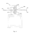
- FIG. 11 shows a schematic split isometric view of an embodiment of a resistive heat generation roller
- FIG. 12 shows a schematic side elevational view of three workpieces during the joining process
- FIG. 13 shows a schematic cross-sectional view of an embodiment of a conductive heat roll joining apparatus
- FIG. 14 shows a schematic side elevational view of an embodiment of a conductive heat roll joining apparatus
- FIG. 15 shows a schematic front elevational view of an embodiment of a conductive heat roll joining apparatus
- FIG. 16 shows a schematic and elevational view of an embodiment of a resistive heat generation roller
- FIG. 17 shows a schematic cross-sectional view of an embodiment of a resistive heat generation roller
- FIG. 18 shows a schematic perspective view of an embodiment of an induction hearing source
- FIG. 19 shows a schematic cross-sectional view of an embodiment of an induction heating roll joining apparatus
- FIG. 20 shows a schematic side elevational view of two resistive heat generation devices creating a bonded structure
- FIG. 21 shows a schematic cross-sectional view of an embodiment of a conductive heat roll joining apparatus
- FIG. 22 shows a schematic isometric view of an embodiment of a resistive heat generation roller
- FIG. 23 shows a schematic isometric view of an embodiment of a resistive heat generation roller
- FIG. 24 shows a schematic isometric view of an embodiment of a resistive heat generation roller
- FIG. 25 shows a schematic isometric view of an embodiment of a resistive heat generation roller.
- the present disclosure includes a method for creating a bonded structure, an apparatus for creating a bonded structure, and a method for creating a zinc-coated bonded structure.
- the disclosure enables a significant advance in the state of the art.
- the preferred embodiments of the methods and apparatus accomplish this by new and novel methods that are configured in unique and novel ways and which demonstrate previously unavailable but preferred and desirable capabilities.
- the description set forth below in connection with the drawings is intended merely as a description of the presently preferred embodiments, and is not intended to represent the only form in which the present invention may be constructed or utilized.
- the description sets forth the designs, functions, means, and methods of implementing the disclosed embodiments. It is to be understood, however, that the same or equivalent functions and features may be accomplished by different embodiments that are also intended to be encompassed within the spirit and scope of the disclosure.
- the methods and apparatus disclosed and claimed herein are related to the joining of workpieces, therefore the workpieces will first be disclosed in detail.
- the methods disclosed produce a bonded structure 50 .
- the bonded structure 50 is composed of at least two workpieces, namely a first workpiece 100 and a second workpiece 200 , as seen in FIG. 2 .
- a first workpiece 100 and a second workpiece 200 as seen in FIG. 2 .
- FIG. 1 which include a first workpiece 100 , a second workpiece 200 , and a third workpiece 300 , as well as structures containing four or more workpiece structures, as seen in FIG. 10 in which a fourth workpiece 400 is illustrated.
- the workpieces may encompass any form that contains a coating as disclosed herein to facilitate the disclosed bonding methods although certain advantages may not be realized. Further, the coating need not be permanently attached to either of the workpieces prior to joining process.
- the structure 50 illustrated in FIG. 3 shows a three workpiece embodiment having a first workpiece 100 , a second workpiece 200 , and a third workpiece 300 .
- the first workpiece 100 includes a first workpiece parent material layer 120 bounded by a first workpiece proximal coating layer 110 on one side and a first workpiece distal coating layer 130 on the opposite side.
- the first workpiece parent material layer 120 has a first workpiece parent material layer thickness 122
- the first workpiece proximal coating layer 110 has a first workpiece proximal coating layer thickness 112
- the first workpiece distal coating layer 130 has a first workpiece distal coating layer thickness 132 ; thereby combining to have a first workpiece overall thickness 102
- the second workpiece 200 includes a second workpiece parent material layer 220 bounded by a second workpiece proximal coating layer 210 and a second workpiece distal coating layer 230 .
- the second workpiece parent material layer 220 has a second workpiece parent material layer thickness 222
- the second workpiece proximal coating layer 210 has a second workpiece proximal coating layer thickness 212
- the second workpiece distal coating layer 230 has a second workpiece distal coating layer thickness 232 ; thereby combining to have a second workpiece overall thickness 202 .
- the illustrated embodiment has a third workpiece parent material layer 320 bounded by a third workpiece proximal coating layer 310 and a third workpiece coating layer 330 .
- the third workpiece parent material layer 320 has a third workpiece parent material layer thickness 322
- the third workpiece proximal coating layer 310 has a third workpiece proximal coating layer thickness 312
- the third workpiece distal coating layer 330 has a third workpiece distal coating layer thickness 332 ; thereby combining to have a third workpiece overall thickness 302 .
- One with skill in the art will recognize the structure of the element nomenclature outlined above and will be capable of carrying if forward to embodiments containing even more workpieces, such as the four workpiece embodiment of FIG. 10 .
- the claimed methods do not require the workpieces to each include all three of the layers just described.
- one particular embodiment merely requires a first workpiece 100 having a first workpiece parent material layer 120 and a first workpiece distal coating layer 130 , and a second workpiece 200 having a second workpiece parent material layer 220 .
- the present methods create a bonded structure 50 by melting and resolidifying a portion of the first workpiece distal coating layer 130 to bond the first workpiece 100 and the second workpiece 200 together without melting, or passing electrical current through, either the first workpiece parent material layer 120 or the second workpiece parent material layer 220 .
- the melting point of the first workpiece distal coating layer 130 is below the melting point of the first workpiece parent material layer 120 or the second workpiece parent material layer 220 .
- the first workpiece distal coating layer thickness 132 is less than four percent of the first workpiece parent material layer thickness 122 .
- Further embodiments incorporate even thinner coating thickness such as a first workpiece distal coating layer thickness 132 of less than one percent of the first workpiece parent material layer thickness 122 .
- Another embodiment includes a metallic sandwich of three or more sheet layers (such as greater than 1 m 2 and more preferably greater than 1 m wide by 2 m long), the center layer of which is a core having alternating peaks and valleys embossed therein, with raised ridges spanning between the peaks in one direction but not in a direction perpendicular thereto.
- the method of creating the bonded structure 50 includes at least three steps; namely the steps of (i) positioning the first workpiece 100 and the second workpiece 200 in at least partial contact, (ii) heating a portion of the first workpiece distal coating layer 130 with a heating source 500 from an initial temperature to a processing temperature within a heating time period to form a substantially liquid zone between a portion of the first workpiece 100 and a portion of the second workpiece 100 , wherein the substantially liquid zone contains a portion of the first workpiece distal coating layer 130 , and (iii) cooling the substantially liquid zone with a cooling system 800 to solidification in a cooling time period to create a bonded connection 900 , illustrated nicely in FIG.
- any of the workpieces may include non-uniformly spaced corrugations, cells, protuberances, projections, or mating surfaces.
- the workpiece that is formed into a shape other than a flat sheet ends up having an overall formed thickness; thus, the second workpiece 200 illustrated in FIG. 3 has a second workpiece formed thickness 204 .
- the “positioning” step mentioned above merely requires that positioning the first workpiece 100 and the second workpiece 200 in at least partial contact so that at least a portion of the first workpiece distal coating layer 130 can be quickly melted and resolidified thereby bonding the two workpieces together.
- the “positioning” step may be as simple as laying one workpiece on top of the other.
- simple clamps or guide brackets may be used to position the workpieces for the “heating” step.
- complex workpieces may be tack welded together to ensure proper initial positioning. Obviously complexly shaped workpieces may require fixtures to maintain the workpieces in the proper position.
- heating and cooling steps may be accomplished by any number of ways; however, one attribute common to the methods disclosed herein is the speed at which they occur.
- the combination of the heating time period and the cooling time period is less than 10 seconds. This short time frame from the start of heating, through melting of the first workpiece distal coating layer 130 , and solidification of the bonded connection 900 allows the present method to join workpieces at a high speed using at least one coating layer that has not previously been used. Further embodiments greatly reduce the combined heating time period and cooling time period, as will be discussed in more detail later.
- the speed of the present methods facilitates the use of a zinc-based distal coating layer 130 .
- the reference to “zinc-based” herein refers to coatings containing at least forty percent zinc.
- soldering and brazing alloys have avoided containing significant quantities of zinc for many reasons.
- Zinc is known to quickly volatilize, which negatively affects the bonded joint, and such volatilization produces zinc vapors that may be harmful to workers. Further, slow processes attempting to avoid such volatilization generally result in the formation of intermetallics that negatively affect the bonded connection 900 .
- An embodiment of the claimed method reflows the zinc-based distal coating layer 130 while significantly reducing, if not eliminating, volatilization and produces a bonded connection that maintains the corrosion resistance afforded by the original zinc-based distal coating layer 130 , as seen in FIG. 6 in which the reflow of the distal coating layer 130 creates a continuous coating around the bonded connection 900 .
- the present embodiment offers increased production efficiency by facilitating the use of zinc-based joining materials.
- many materials are commonly available with zinc-based coatings for corrosion resistance.
- the hot-dip coating family alone includes the following commonly available zinc-based coatings having substantial amounts of zinc: galvanize, galvaneel, 55% aluminum-zinc alloy, zinc-5% aluminum alloy, and zinc-aluminum-magnesium alloy.
- the present method facilitates the use of such common material coatings to join numerous workpieces, without the need to add separate soldering or brazing alloys, and in one embodiment, without the need for any flux or a vacuum environment. Additional coating layers and parent material layers will be discussed in detail later.
- the claimed methods may utilize any heating source 500 and cooling source 800 capable of satisfying the requirement that the combination of the heating time period and the cooling time period is less than 10 seconds, while not transmitting electrical current through the workpieces.
- Such heating sources 500 include, but are not limited to, a conduction heating source 600 or an induction heating source 700 , as seen in FIGS. 1 and 9 respectively.
- the conduction heating source 600 will be now described in detail.
- the conduction heating source 600 may be any heating device that can conductively heat the first workpiece distal coating layer 130 to a processing temperature above the first workpiece distal coating layer 130 melting point within the required heating time period.
- the conduction heating source 600 may be placed in contact with either the first workpiece 100 or the second workpiece 200 to conductively heat the first workpiece distal coating layer 130 .
- multiple conduction heating sources 600 as seen in FIG. 4 , may be used to further increase the speed of the method.
- the conduction heating source 600 may be in the form of a bar or plate that is simply placed on one of the workpieces to bond a portion of the structure, which is then advanced to bond the next area in a step-wise manner, or the conduction heating source 600 may be designed to bond every portion of the structure 50 that needs bonding in a single cycle.
- the conduction heating source 600 may be in the form of a roller than facilitates relative movement between the conduction heating source 600 and the first workpiece distal coating layer 130 to produce a continuous bonding environment.
- the conductive heating source 600 may be heating in any number of ways.
- the conductive heating source 600 is at a higher temperature than the first workpiece distal coating layer 130 , and in contact with at least one of the workpieces, heat is conductively transferred from the conductive heating source 600 to the first workpiece distal coating layer 130 .
- the first workpiece distal coating layer 130 is located between the first workpiece 100 and the second workpiece 200 and the heat is conductively transferred through the first workpiece 100 to heat and melt a portion of the first workpiece distal coating layer 130 , however the heat may be conductively transferred through the second workpiece 200 to melt a portion of the first workpiece distal coating layer 130 .
- the conduction heating source 600 may itself be heating in any number of ways, including, but not limited to, radiant heating, induction heating, infrared heating, and resistive heating, just to name a few.
- the conduction heating source 600 is a resistive heat generation device 610 .
- the resistive heat generation device 610 is resistively heated by the passage of electrical current through the resistive heat generative device 610 , thereby elevating the temperature of the resistive heat generation device 610 , which then conductively transfers heat to the first workpiece distal coating layer 130 .
- the current may be current that is induced in the resistive heat generation device 610 , or it may be current originating with a power source that is in electrical communication with the resistive heat generation device 610 .
- the resistive heat generation device 610 may include a high electrical resistivity insulator 650 , seen in FIGS. 7 and 8 , in contact with the bonded structure 50 to further guard against the passage of electrical current form the resistive heat generation device 610 to the bonded structure, and to reduce the amount of coating material that adheres to the resistive heat generation device 610 .
- the high electrical resistivity insulator 650 may be constructed of materials that resist wetting of the melted coatings.
- the electrical resistivity of the high electrical resistivity insulator 650 is at least one hundred times greater than the electrical resistivity of the current carrying portion of the resistive heat generation device 610 .
- Yet another embodiment has a thermal conductivity of the high electrical resistivity insulator 650 that is at least fifty percent of the thermal conductivity of the current carrying portion of the resistive heat generation device 610 .
- the high electrical resistivity insulator 650 has an electrical resistivity of at least 10 13 ohm-cm and a thermal conductivity of at least 150 W/m° K, thereby guarding against the passage of electrical current into the structure 50 while facilitating effective conductive heat transfer to the structure 50 .
- An even further embodiment has found desirable performance utilizing a higher electrical resistivity insulator 650 constructed of aluminum nitride in light of desirable electrical and heat transfer properties, as well as its resistance to wetting by melted coating materials.
- An aluminum nitride high electrical resistivity insulator 650 may have an insulator thickness 652 as little as 1 mm and still provide the desired performance.
- the movement of electrical current through a portion of the resistive heat generation roller 620 is further refined by controlling the current path within the resistive heat generation roller 620 to reduce the amount of power required to resistively heat the roller 620 at the point of contact with the structure 50 to a contact surface setpoint temperature above the melting temperature of the first workpiece distal coating layer 130 .
- one embodiment of the method allows the current to flow into the resistive heat generation roller 620 at a point near the circumference of the resistive heat generation roller 620 , and near to the first workpiece distal coating layer 130 , while the exit point from the resistive heat generation roller 620 is longitudinally at the opposite end of the resistive heat generation roller 620 , but also at a point near the circumference of the resistive heat generation roller 620 , and near to the first workpiece distal coating layer 130 , as illustrated nicely in FIGS. 11 and 15 .
- FIG. 11 and 15 See the embodiment of FIG.
- the electrical current path is controlled so that it enters the roller near the contact point with the first workpiece 100 , and the current traverses the roller 620 longitudinally near the contact point with the first workpiece 100 , thus near the perimeter of the roller 620 , until it exits the roller 620 at the opposite end of the roller 620 , yet still near the contact point with the first workpiece 100 .
- this same principal is incorporated in any of the embodiments disclosed herein, whereby the current is induced in the roller 620 .
- the embodiments of FIGS. 20-25 illustrate at least one induction heating source 700 inducing an electrical current within the resistive heat generation roller 620 .
- the resistive heat generation roller 620 is constructed so that the electrical current passes through, or is induced within, the resistive heat generation roller 620 within a conduction distance 645 , seen in FIG. 4 , from the perimeter of the resistive heat generation roller 620 , wherein the conduction distance 645 is less than twenty-five percent of the roller diameter 622 .
- This may be accomplished by utilizing a hollow roller 620 or a multi-component roller 620 to keep the current flow near the perimeter of the roller 620 .
- a further embodiment takes this a step further and maintains the current path even closer to the perimeter of the roller 620 , in fact, in this embodiment the conduction distance 645 is less than twelve and one-half percent of the roller diameter 622 .
- the resistive heat generation roller 620 includes a plurality of resistive heat generation roller sections 630 separated from one another by a plurality of roller section gaps 640 preventing the passage of electrical current between adjacent resistive heat generation roller sections 630 .
- the electrical current passes through no more than two of the plurality of resistive heat generation roller sections 630 at a time, thereby requiring less power to resistively heat the desired particular resistive heat generation roller sections 630 to a temperature that facilitates conductively heating a portion of the first workpiece distal coating layer 130 to its melting point.
- This same power conservation principle may be incorporated in the embodiments in which current is induced within the resistive heat generation roller 620 by constructing the roller largely of non-electrically conductive materials such that the induction heating source 700 only induces current in a small portion of the resistive heat generation roller 620 . Additionally, further embodiments reduce power consumption by locating the induction heating source 700 internal to the resistive heat generation roller 620 as seen in FIG. 25 .
- the heat generation roller 620 has a roller diameter 622 , and thus a roller circumference
- the resistive heat generation roller section 630 has a section width 632 , which is measured along the outermost surface of the roller section 630 , and a section thickness 634 , which is measured at the thickest portion of the roller section 630 .
- One particular embodiment directs the current through the resistive heat generation roller 620 by having the section width 632 of the current carrying resistive heat generation roller section 630 be less than seventy-five percent of the roller diameter 622 .
- separate embodiments even more narrowly control the current path through the resistive heat generation roller 620 by reducing the section width 632 of the current carrying resistive heat generation roller section 630 to less than forty percent of the roller diameter 622 .
- Yet another embodiment narrows the section width even further by having the section width 632 of the current carrying resistive heat generation roller section 630 that is less than thirty percent of the roller diameter 622 .
- these unique relationships may produce embodiments with 20 , or more, separate resistive heat generation roller sections 630 , as seen in FIG. 8 .
- the embodiment illustrated in FIG. 16 has more than 40 resistive heat generation roller sections 630 to further take advantage of this unique relationship and reduce the power requirements by selectively heating only a portion of the resistive heat generation roller 620 .
- the conductive heating step further includes passing electrical current through, or inducing current within, a resistive heat generation device 610 that is in contact with the structure thereby resistively heating the resistive heat generation device 610 without passing electrical current through the structure, and the resistive heat generation device 610 subsequently conductively transfers heat to either, or both, the first workpiece distal coating layer 130 and the second workpiece proximal coating layer 210 .
- the amount of current passed through, or induced within the resistive heat generation device 610 is carefully controlled and associated with a unique combination of variables.
- the resistive roll current constant ranges from 0.8 to 1.2, and the density, resistivity, and heat capacity refers to those values for the workpiece parent material layer.
- the first workpiece parent material layer 120 and the second workpiece parent material layer 220 will be composed of the same material and therefore will have the same density, resistivity, and heat capacity, however this is not required.
- the current calculation shall be performed for each material and the larger of the two values transmitted through the resistive heat generation device 610 .
- the calculated current requirement may also be used to determine the necessary voltage.
- the voltage is carefully controlled and associated with a unique combination of variables.
- the resistive roll voltage current ranges from 0.8 to 1.2, and the resistivity refers to the resistivity of the workpiece parent material layer 120 .
- first workpiece parent material layer and the second workpiece parent material layer 220 will be composed of the same material and therefore will have the same material properties, however this is not required.
- the voltage calculation shall be performed for each material and the larger of the two values transmitted through the resistive heat generation device 610 .
- the resistive heat generation roller 620 may be made of any material that possesses enough electrical resistance to achieve the desired contact surface setpoint temperature within the necessary heating period, and possesses desirable mechanical properties at elevated temperatures.
- the heat generation roller sections 630 are constructed of a molybdenum alloy, however yet another embodiment incorporates a resistive heat generation roller 620 in which the electrically conductive portion is constructed of Inconel.
- the coefficient of thermal expansion of the resistive heat generation device 610 should be similar to the coefficient of thermal expansion of the high electrical resistivity insulator 650 , ideally differing by no more than twenty percent.
- one embodiment utilizes select materials to obtain coefficients of thermal expansion that differ by less than 1.0 ⁇ 10 ⁇ 6 /K, thereby limiting different expansion at elevated temperatures between the resistive heat generation device 610 and the high electrical resistivity insulator 650 to increase the useful life of the conductive heating source 600 .
- One such material combination incorporates a high electrical resistivity insulator 650 of aluminum nitride with a resistive heat generation device 610 of a molybdenum alloy, thereby closely matching the coefficients of thermal expansion and providing the desired electrical properties of both elements, while ensuring adequate conductive heat transfer and resistance to wetting from the melting coating material.
- Another such material combination incorporates a high electrical resistivity insulator 650 of aluminum nitride with a resistive heat generation device 610 of a nickel-based alloy, thereby closely matching the coefficients of thermal expansion and providing the desired electrical properties of both elements, while ensuring adequate conductive heat transfer and resistance to wetting from the melting coating material.
- Controlling the passage of electrical current through no more than two of the plurality of resistive heat generation roller sections 630 at a time as the resistive heat generation roller 620 rotates requires a special current flow path.
- One such embodiment is illustrated schematically in FIG. 11 .
- current flows from the input conductor 624 through an input contactor 628 a to no more than two of the resistive heat generation roller sections 630 .
- the roller section 630 is resistively heated and the current leaves the roller section 630 through an output contactor 628 b connected to an output conductor 626 .
- the input contactor 628 a and the output contactor 628 b are stationary, thereby dictating the position of the roller section 630 that is resistively heated, but they allow the resistive heat generation roller 620 to rotate while maintaining electrical continuity from the input conductor 624 to the output conductor 626 .
- the input contactor 628 a and the output contactor 628 b may be roller contacts, as schematically illustrated in FIG. 11 , or sliding contacts, as schematically illustrated in FIG. 15 .
- the input contactor 628 a and the output contractor 628 b may be biased to maintain a biasing force against the resistive heat generation roller 620 , and may be sized to account for the roller section gaps 640 such that there may be a short period in which current is directed into two adjacent roller sections 630 .
- the input contactor 628 a exerts a contract force of at least 50 lbf to the current carrying resistive heat generation roller 620 and the output contactor 628 b exerts a contact force at least 40 lbf to the current carrying resistive heat generation roller 620 .
- the contact force of the input contactor 628 a and the output contactor 628 b have to be carefully balanced with the torque such a force adds to the resistive heat generation roller 620 resistance to rotating, yet the contact force must be high enough to ensure that the contactor and the associated interface to the resistive heat generation roller 620 , are not a large portion of the overall electrical resistance in the current path from the input contactor 628 a through the resistive heat generation roller 620 and out the output contractor 628 b .
- the input and output contact forces are each approximately 100 lbf, which does not add an unduly large torque on the resistive heat generation roller 620 while ensuring that the electrical resistance associated with the contactors 628 a , 628 b and associated interfaces is less than twenty percent of the electrical resistance of a resistive heat generation roller section 630 .
- the contactors 628 a , 628 b are liquid cooled.
- the plurality of roller section gaps 640 prevents the passage of electrical current between adjacent resistive heat generation roller sections 630 .
- the gaps 640 may simply be voids between the adjacent resistive heat generation roller sections 630 .
- One embodiment incorporates gaps 640 that separate adjacent resistive heat generation roller sections 630 by at least one percent of the section width 632 .
- the gaps 640 are at least 0.25 mm, thereby ensuring electrical current does not pass between adjacent sections 630 .
- the gap 640 is reduced by filling the gap 640 with an electrical insulator to prevent current passage, and providing a convenient method of ensuring a consistent gap size between the resistive heat generation roller sections 630 .
- the high resistivity insulator 650 partially fills the roller section gaps 640 .
- additional methods of controlling the current pathway through the resistive heat generation roller 620 include careful selection of the materials of the resistive heat generation roller 620 and by creating localized areas of the roller 620 having higher resistance to the flow of current, or areas of the roller 620 that are constructed of non-electricity conductive materials.
- One additional method of controlling the current pathway is to vary the thickness of the current carrying portion of the resistive heat generation roller 620 .
- the resistive heat generation roller 620 may include one, or more, selective cooling systems to maintain localization of the roll hot zone, even with an implicit diffuse current density.
- another embodiment of the claimed methods further includes the step of compressing at least one of the first workpiece 100 and the second workpiece 200 from an unbonded structure initial thickness 52 to a bonding thickness 56 , as illustrated in FIG. 12 .
- the compression results in a bonding thickness 56 that is at least 2 percent less than the initial thickness 52 , thereby increasing a roller transverse contact length 632 of the resistive heat general roller 620 to the bonded structure to at least one percent of a roller diameter 622 .
- the roller transverse contact length 623 is measured in the direction that the resistive heat generation roller 620 rotates from the point at which roller 620 and structure 50 first come in contact to the point at which they are no longer in contact, and is measured along the associated contact curve.
- Yet another embodiment further includes the step of compressing at least one of the first workpiece 100 and the second workpiece 200 from an unbonded structure initial thickness 52 to a bonding thickness 56 , wherein the bonding thickness 56 is at least 2 percent less than the initial thickness 52 thereby increasing a roller transverse contact length 623 of the resistive heat general roller 620 to the structure to at least five percent of the section width 630 .
- another similar embodiment incorporating relatively flexible workpieces simply deflects the structure 50 around the resistive heat generation roller 620 , rather than compressing the structure 50 , to achieve the same benefits.
- there may be some degree of spring-back from the bonding thickness 56 to a structure joined thickness 54 which can further increase the roller transverse contact length 623 .
- Increasing the contact area, and thus the contact time, between the resistive heat generation roller 620 and the structure 50 allows for greater conductive heat transfer to melt a portion of the first workpiece distal coating layer 130 .
- one particular embodiment produces a bonded structure 50 that has a structure joined thickness 54 is at least five percent less than the structure initial thickness 52 .
- the temperature rise in the structure 50 following initial contact with the resistive heat generation roller 620 can be defined as:
- a conductive heat roll joining apparatus 60 will be disclosed in detail, however this is not the only configuration that may carry out the disclosed methods.
- the presently discussed embodiment is a very small conductive heat roll joining apparatus 60 having rollers 620 that are less than twelve inches long.
- the disclosed methods may be used to produce structures 50 that are significantly wider by incorporating rollers 620 that are many feet in length.
- this particular embodiment of the apparatus 60 includes two resistive heat generation rollers 620 , however as previously disclosed, and illustrated in FIGS. 2 and 12 , only one resistive heat generation roller 620 is necessary.
- FIG. 13-24 this particular embodiment of the apparatus 60 includes two resistive heat generation rollers 620 , however as previously disclosed, and illustrated in FIGS. 2 and 12 , only one resistive heat generation roller 620 is necessary.
- FIG. 13-24 this particular embodiment of the apparatus 60 includes two resistive heat generation rollers 620 , however as previously disclosed, and illustrated in FIGS. 2 and 12 , only one resistive heat generation roller 620 is necessary.
- FIG. 13 includes an inlet feed guide 62 and an outlet feed guide to guide 64 the structure through the apparatus 60 .
- Each of the resistive heat generation rollers 620 of this embodiment are mounted on a central shaft 625 , which is supported by a shaft mount 627 at each end, seen in FIG. 14 .
- a front elevation view of the apparatus 60 is illustrated in FIG. 15 showing the inlet side of the two resistive heat generation rollers 620 .
- the at least one resistive heat generation roller 620 of the conductive heat roll joining apparatus 60 may include any of the previously disclosed resistive heat generation rollers 620 , however, the specific embodiment illustrated in FIGS. 16 and 17 include multiple resistive heat generation roller sections 630 held to the central shaft 625 via an electrically insulated section retainer 636 .
- the section retainer 636 is an insulated stainless steel compression band, however the sections 630 may be mounted to, or bonded to, the central shaft 625 in any number of manners.
- the upper roller shaft mounts 627 and the lower roller shaft mounts 627 are independently mounted to the apparatus 60 so that the amount of space between the rollers 620 may be adjusted.
- the apparatus 60 may include a load control system 629 , seen in FIG. 15 , that is used to adjust the space between the rollers 620 , and optionally may apply a load to at least one of the central shafts 625 , and thus at least one of the rollers 620 .
- the load control system 629 may be mechanical, hydraulic, pneumatic, or electromagnetic, just to name a few of the methods of applying a load to the central shaft 625 .
- the load control system 629 may be manual or automatic.
- the load control system 629 may be set to automatically adjust the load applied to the central shaft 625 to obtain a desired compression, deflection, or constant bonding forced regardless of structure thickness.
- Sensors may be included in the apparatus 60 to monitor such variables and send information back to the load control system 629 for analysis and to make any necessary adjustments to the load applied to the central shaft 625 throughout the relative movement of the structure 50 and the rollers 620 .
- One particular embodiment includes the step of applying a compressive load of at least 250 N to the structure during the solidification process.
- the induction heating source 700 may be independently mounted to the apparatus 60 so that the amount of space between the induction heating source 700 and the rollers 620 may be adjusted.
- any of the embodiments may further include the step of cooling the conductive heating source 600 to ensure operational efficiency and the desired heat transfer to the first workpiece distal coating layer 130 .
- Such cooling may be carried out with at least one resistive heat generation device cooling passageway 660 , illustrated in FIGS. 7 and 17 .
- the cooling passageway 660 may improve passive cooling of the conduction heating source 600 , or may be an active cooling passageway 660 through which a cooling fluid may flow.
- the cooling may be carried out in any number of ways.
- the structure 50 may be cooled with a fluid spray system 810 , as seen in FIG. 4 , or the structure 50 may incorporate a flood cooling system incorporated into an outlet feed guide 64 , as seen in FIG. 13 , thereby further selectively cooling the exit side of the conductive heating source 600 .
- the structure 50 may be cooled with a cooling roller, often referred to as a quench roller, positioned immediately after the heating source 500 .
- the step of cooling the substantially liquid zone with a cooling system 800 to solidification occurs within a distance of less than ten times the combined thickness of the first workpiece parent material layer thickness 122 and the second workpiece parent material layer thickness 222 , further reducing the likelihood of movement between the workpieces prior to solidification and according reducing amount of external contact that must be placed on the structure 50 after it is heated.
- the present methods may be used to create a bonded zinc-coated structure 50 by joining a first workpiece 100 having a zinc-based first workpiece proximal coating layer 110 and a zinc-based first workpiece distal coating layer 130 to a second workpiece 200 having a zinc-based second workpiece proximal coating layer 210 and a zinc-based second workpiece distal coating layer 230 .
- Such zinc-based coatings may be applied to the workpieces 100 , 200 in any number of widely known processes, including, but not limited to, hot-dip coating processes, electroplated coating processes, spray coating processes, powder coating processes, and cladding processes, just to name a few.
- Embodiments of the structure 50 incorporating sheet based workpieces are most commonly associated with hot-dip coating processes which are used to produce sheets having zinc-based coatings including, but not limited to galvanize, galvanneal, 55% aluminum-zinc alloy, zinc-5% aluminum alloy, and zinc-aluminum-magnesium alloy.
- One particular embodiment with wide ranging applications utilizes the methods disclosed herein to create a galvanized structure 50 by joining a galvanized first workpiece 100 and a galvanized second workpiece 200 .
- all four coating layers namely the first workpiece proximal coating layer 110 , the first workpiece distal coating layer 130 , the second workpiece proximal coating layer 210 , and the second workpiece distal coating layer 230 , hereafter referred to as the coating layers 110 , 130 , 210 , 230 , include zinc carbonate.
- the combined mass of the first workpiece proximal coating layer 110 and the first workpiece distal coating layer 130 is at least 90 grams per square meter
- the combined mass of the second workpiece proximal coating layer 210 and the second workpiece distal coating layer 230 is at least 90 grams per square meter.
- the workpieces 100 , 200 may be defined by the ASTM designator system as having at least G30 (0.30 ounce per square foot of sheet) coatings in the inch-pound convention, or as having at least Z90 (90 grams per square meter of sheet) coatings in the S1 coating mass designation.
- the coating layer thickness will be less than four percent of the parent material layer thickness.
- the present methods and apparatuses are not limited to metallic parent materials or coating materials.
- the present galvanized embodiment is directed specifically to galvanized workpieces that have not been skin passed, or temper rolled.
- the methods and apparatuses disclosed herein facilitate the joining of two such zinc-coated workpieces to create a zinc-coated structure that maintains a zinc-coating around the bonded connection 900 , seen in FIG. 6 , so as to provide all the benefits traditionally afforded to zinc-coated workpieces, even around the connection point thus maintaining the desirable corrosion resistance.
- the presently defined methods quickly melt a portion of the zinc-based coating, while minimizing volitization and ensuring adequate reflow of the coating, and resolidify the coating under controlled conditions to produce a particularly effective bonded connection 900 . These methods may be carried out without the use of a vacuum brazing chamber and free from flux.
- the present embodiments of the present methods and apparatus may utilize custom coatings not bound by today's commonly available coating compositions.
- Such commonly available coating compositions include widely available galvanized coatings containing less than one-half percent aluminum, and zinc-aluminum hot-dip coatings four percent to six percent aluminum, but may include compositions containing aluminum in the one-half percent to four percent range as well.
- Alternative coating compositions may include eight percent to eleven percent iron, as well as compositions having at least fifty percent aluminum and approximately forty percent zinc.
- the coating composition may include magnesium, such as in a zinc-aluminum-magnesium coating having four percent to twelve percent aluminum, and two percent magnesium.
- embodiments of the coating layers containing aluminum may further containing four percent to twelve percent silicon.
- Further coating compositions may include nickel-phosphorus coatings, copper coatings, and copper-phosphorus coatings. While many of the coating compositions refer generally to sheet steel coatings, the present methods and apparatuses may utilize coating layers common for other widely available metals, including but not limited to, first workpiece distal coating layer 130 containing lead alloys and coatings containing tin, such as terne coatings.
- the heating time period is the length of time required to heat the first workpiece distal coating layer 130 from an initial temperature to a processing temperature, wherein the processing temperature is above the melting point of the first workpiece distal coating layer 130 , but below the melting point of the first workpiece parent material layer 120 .
- the coating layers are generally the same material, however that is not required.
- the heating time period is the length of time required to heat the first workpiece distal coating layer 130 and the second workpiece proximal coating layer 210 from an initial temperature to a processing temperature, wherein the processing temperature is above the greater of the melting point of the first workpiece distal coating layer 130 and the melting point of the second workpiece proximal coating layer 210 .
- the initial temperature is generally room temperature, but may be an elevated temperature if the workpiece has been preheated to accomplish another purpose. Thus, in one embodiment the initial temperature is less than 50 degrees Celsius.
- the present inventions and apparatus encompass the field of soldering as well as brazing and thus the processing temperature is not bound by the commonly accepted 400 degree Celsius differentiation point.
- the embodiments incorporating zinc-based coatings, or aluminum-based coatings must clearly have a processing temperature above 400 degrees Celsius. In fact, these embodiments incorporate a processing temperature in excess of 410 degrees Celsius.
- embodiments directed to the apparatus refer to another temperature, namely the contact surface setpoint.
- the contact surface setpoint is likely to be higher than the processing temperature so that the heat may be quickly conductively transferred to the first workpiece distal coating layer 130 and result in melting of a portion of the first workpiece distal coating layer 130 .
- a contact surface setpoint period from the time that the resistive heat generation roller 620 beings increasing in temperature to the point at which the contact surface setpoint temperature is achieved is less than five seconds.
- the thermal cycle of the first workpiece distal coating layer 130 is likely to include conductively heating the coating layer 130 from less than 50 degrees Celsius to over 410 degrees Celsius, allowing for appropriate reflow while guarding against volatilization and intermetallic formation, and cooling the coating layer to less than 410 degrees Celsius in less than ten seconds. Further, embodiments of the present methods have achieved this cycle in far less than 10 seconds. In fact, bonded connection exhibiting good properties have been achieved with a heating time period of less than 7 seconds and a cooling time period of less than 1 second. Even further, acceptable zinc-based bonded connections have been achieved with a heating time period of less than 1 second and a cooling time period of less than 500 milliseconds.
- a heating time period of less than 400 milliseconds and a cooling time period of less than 200 milliseconds is achievable with the disclosed methods and apparatuses with a brazing temperature of 600 degrees Celsius joining three 0.2 mm thick workpieces to create a 1.5 mm thick bonded galvanized structure having approximately 5 micrometer thick galvanized layer at the bonded connection 900 between the workpieces.
- These quick cycle times ensure that the liquid zone does not need to be externally constrained to produce a good bonded connection, and allow for high production rates.
- the very fast thermal cycle time of the present methods and apparatus facilitate production rates that include linear travel speeds of the structure in the range of 1 meter per minute up to 10 meters per minute.
- the present methods and apparatuses may incorporate very fine temperature control, particularly when joining aluminum workpieces with aluminum-based coating layers where the temperature difference between that required to melt the coating layer and that required to melt the parent material may differ by as little as forty to fifty degrees Fahrenheit, and similar combinations.
- the methods and apparatuses in this disclosure are not limited to any one particular parent material or any one particular coating material, and may be used to join any combination of workpieces provided one of the workpieces has a coating layer that may be conductively heated to solidification as disclosed herein to bond the two workpieces together.
- aluminum is widely available in a precoated manner that may be bonded to another workpiece via the present methods and apparatuses.
- stainless steel is widely available in a precoated manner that may be bonded to another workpiece via the present methods and apparatuses, such stainless steel embodiments include, but are not limited to, copper coated stainless steel.
- the combinations of parent materials and coating materials may include electroless nickel plated mild steels.
- custom coating compositions may be developed and applied to workpieces so that they may take advantage of the efficiencies offered by the present methods and apparatuses.
- the heating sources 500 may include, but are not limited to, a conduction heating source 600 and an induction heating source 700 ; an embodiment illustrating a schematic induction heating source 700 is shown in FIGS. 9 and 18-24 .
- the induction heating source 700 may be configured to heat the workpieces, as seen in FIGS. 18 and 19 , or alternatively may be configured to heat the resistive heat generation device 610 , from the inside or outside, as seen in FIGS. 20-25 .
- at least one compression roller 710 keeps the workpieces in intimate contact during the solidification process.
- the induction heating source 700 serves as the transformer primary and conductive workpieces, or an electrically conductive portion of the resistive heat generation device 610 , become a short circuit secondary.
- the conductive workpieces, or the electrically conductive portion of the resistive heat generation device 610 are exposed to the magnetic field generated by the induction heating source and eddy currents are induced within at least one of the workpieces, or a portion of the resistive heat generation device 610 .
- the eddy currents flow against the electrical resistivity of the workpieces, or a portion of the resistive heat generation device 610 , generating precise and localized heat without any direct contact with the induction heating source 700 .
- the heated workpiece, or resistive heat generation device 610 then conductively heats a portion of the first workpiece distal coating layer 130 to a temperature above its melting point. All of the previous disclosure applies equally to the induction heating source 700 embodiment.
- the induction heating source 700 includes an induction coil, which may be specially-shaped copper tubing through which alternating electrical current is passed, creating a varying magnetic field.
- an induction coil which may be specially-shaped copper tubing through which alternating electrical current is passed, creating a varying magnetic field.
- One particular embodiment utilizes a two turn induction heating coil connected to a 12 kW power supply, which is able to finely control the temperature of the workpieces to ensure conductive heat transfer from the parent material layers quickly melts the first workpiece distal coating layer 130 and quickly allows solidification.
- the induction heating coil operates between 150 kHz to 200 kHz at 75-125 V and a current flow of 6-10 amps.
- the induction heating source 700 is a curved induction coil designed to generally follow the curvature of the resistive heat generation roller 620 , as seen in FIGS. 20-24 .
- the induction coil may be designed to only heat a select portion of the resistive heat generation roller 620 immediately before it comes in contact with the workpiece.
- the preferred embodiments incorporate an induction heating source 700 carefully designed and positioned such that less than fifty percent of the circumference of the resistive heat generation roller 620 is heated to the processing temperature by the induction heating source 700 , thereby reducing the power requirements and only heating a desired portion of the resistive heat generation roller 620 .
- an even further embodiment takes this even further and ensures that less than thirty-three percent of the circumference of the resistive heat generation roller 620 is heated to the processing temperature by the induction heating source 700 .
- the induction heating source 700 is located inside the resistive heat generation roller 620 .
- the induction heating source 700 remains stationary inside the roller 620 as the roller 620 rotates around the heating source, although the induction heating source 700 may rotate as well. Locating the induction heating source 700 within the roller 620 permits particularly desirable current induction within the roller 620 .
- the induction heating source 700 is arranged in a helical coil configuration; however, other configurations may be incorporated in this design.
Landscapes
- Engineering & Computer Science (AREA)
- Mechanical Engineering (AREA)
- Chemical & Material Sciences (AREA)
- Materials Engineering (AREA)
- Metallurgy (AREA)
- Organic Chemistry (AREA)
- Health & Medical Sciences (AREA)
- Dermatology (AREA)
- General Health & Medical Sciences (AREA)
- General Induction Heating (AREA)
Abstract
Description
Where, in a two workpiece embodiment such as that illustrated in
-
- t1=first workpiece
overall thickness 102; - t2=second workpiece formed
thickness 204; - x=distance traveled along the roller
transverse contact length 623; - Troll—contact surface setpoint temperature;
- To=ambient temperature;
- S=structure travel speed; and
- α=thermal diffusivity.
This relationship is then used to define the necessary rollertransverse contact length 623 to allow thestructure 50 to achieve the equilibrium contact surface setpoint temperature (Troll), while considering the structure travel speed S. Theroller diameter 622 can then be related to the rollertransverse contact length 623 and the amount of compression of thestructure 50 by the resistiveheat generation roller 620. The amount of compression is measured as the reduction from the structureinitial thickness 52 to thebonding thickness 56, as seen inFIG. 12 . Thus, the roller diameter=[(roller transverse contact length)2+4*(compression)]/(4*(compression)). Then, in one embodiment the compression is limited to ten percent, thereby yielding a final result of roller diameter=[50*(roller transverse contact length)2+2*(t1+t2)2]/[20*(t1+t2)]. In yet another embodiment the compression preferably results in abonding thickness 56 that is at least 2 percent less than theinitial thickness 52, thereby increasing a rollertransverse contact length 623 of the resistive heatgeneral roller 620 to the bonded structure to at least one percent of aroller diameter 622, but less than 10 percent less than theinitial thickness 52, to avoid stresses and a tendency to spring back and pull the joint apart.
- t1=first workpiece
Claims (49)
Priority Applications (1)
| Application Number | Priority Date | Filing Date | Title |
|---|---|---|---|
| US15/508,967 US10112248B2 (en) | 2014-09-09 | 2015-09-08 | Method of creating a bonded structure and apparatuses for same |
Applications Claiming Priority (3)
| Application Number | Priority Date | Filing Date | Title |
|---|---|---|---|
| US201462047928P | 2014-09-09 | 2014-09-09 | |
| PCT/US2015/049010 WO2016040365A1 (en) | 2014-09-09 | 2015-09-08 | Method of creating a bonded structure and appartuses for same |
| US15/508,967 US10112248B2 (en) | 2014-09-09 | 2015-09-08 | Method of creating a bonded structure and apparatuses for same |
Publications (2)
| Publication Number | Publication Date |
|---|---|
| US20170274465A1 US20170274465A1 (en) | 2017-09-28 |
| US10112248B2 true US10112248B2 (en) | 2018-10-30 |
Family
ID=55459489
Family Applications (1)
| Application Number | Title | Priority Date | Filing Date |
|---|---|---|---|
| US15/508,967 Active 2035-09-16 US10112248B2 (en) | 2014-09-09 | 2015-09-08 | Method of creating a bonded structure and apparatuses for same |
Country Status (2)
| Country | Link |
|---|---|
| US (1) | US10112248B2 (en) |
| WO (1) | WO2016040365A1 (en) |
Cited By (3)
| Publication number | Priority date | Publication date | Assignee | Title |
|---|---|---|---|---|
| US10507875B1 (en) | 2018-12-21 | 2019-12-17 | Celltech Metals Inc. | Trailer wall including logistics post |
| US10710328B2 (en) | 2014-04-22 | 2020-07-14 | Celltech Metals, Inc. | Wheeled trailer sandwich structure including grooved outer sheet |
| US20230129706A1 (en) * | 2020-03-13 | 2023-04-27 | Mink Campers Ehf. | Sports camper structure |
Families Citing this family (2)
| Publication number | Priority date | Publication date | Assignee | Title |
|---|---|---|---|---|
| WO2016040365A1 (en) | 2014-09-09 | 2016-03-17 | Celltech Metals Inc. | Method of creating a bonded structure and appartuses for same |
| DE102015106298B4 (en) * | 2015-04-24 | 2017-01-26 | Semikron Elektronik Gmbh & Co. Kg | Device, method and system for inhomogeneous cooling of a flat object |
Citations (83)
| Publication number | Priority date | Publication date | Assignee | Title |
|---|---|---|---|---|
| US2087010A (en) | 1934-06-26 | 1937-07-13 | Mckay Machine Co | Method and apparatus for preventing coil breaks in sheet metal |
| US2391997A (en) | 1942-03-26 | 1946-01-01 | Lilly Florence Shirley Noble | Composite slab sheet or plate |
| US2441476A (en) | 1944-08-10 | 1948-05-11 | Glenn L Martin Co | Reinforced structural sheet |
| US2481046A (en) | 1947-11-13 | 1949-09-06 | Western Engineering Associates | Panel structure |
| US2691208A (en) * | 1948-08-14 | 1954-10-12 | Joseph B Brennan | Method of laminating strip metal |
| US2738297A (en) | 1952-06-10 | 1956-03-13 | Pfistershammer Joseph | Honeycomb-type structural materials and method of making same |
| US2809908A (en) | 1953-12-28 | 1957-10-15 | Keyes Fibre Co | Construction panel |
| US2950788A (en) | 1955-08-30 | 1960-08-30 | Robertson Co H H | Cellular steel floor |
| US3013641A (en) | 1957-04-29 | 1961-12-19 | Thompson Ramo Wooldridge Inc | Structural element |
| US3071853A (en) | 1955-10-17 | 1963-01-08 | Solar Aircraft Co | Method and apparatus for making brazed honeycomb |
| US3086899A (en) | 1956-05-04 | 1963-04-23 | Dow Chemical Co | Constructional lamina |
| US3151712A (en) | 1960-11-30 | 1964-10-06 | Budd Co | Insulating structure |
| US3173383A (en) | 1962-04-24 | 1965-03-16 | Budd Co | Railway vehicle floor structure |
| US3217845A (en) | 1961-02-06 | 1965-11-16 | Crown Zellerbach Corp | Rigidified corrugated structure |
| US3227598A (en) | 1960-12-02 | 1966-01-04 | Wayne F Robb | Core structure |
| US3269004A (en) * | 1963-05-06 | 1966-08-30 | Allegheny Ludlum Steel | Process of roll bonding stainless steel and aluminum |
| US3432859A (en) | 1963-01-29 | 1969-03-11 | Gen Electric | Radome and method for making same |
| US3481642A (en) | 1966-06-17 | 1969-12-02 | Bonallack & Sons Ltd | Insulated bodies for commercial vehicles |
| US3525663A (en) | 1967-03-09 | 1970-08-25 | Jesse R Hale | Anticlastic cellular core structure having biaxial rectilinear truss patterns |
| US3597891A (en) | 1969-10-02 | 1971-08-10 | Mc Donnell Douglas Corp | Interior absorptive panel |
| US3742663A (en) | 1971-08-02 | 1973-07-03 | Mc Donnell Douglas Corp | Panel blocking |
| US3811177A (en) | 1969-12-15 | 1974-05-21 | Vaw Ver Aluminium Werke Ag | Process for brazing workpieces of aluminum containing material |
| US3834487A (en) | 1973-03-08 | 1974-09-10 | J Hale | Sandwich core panel with structural decoupling between the outer face sheets thereof |
| US3865679A (en) | 1973-07-09 | 1975-02-11 | Jesse R Hale | Sandwich panel having cellular core structure with reinforcing elements |
| US3876492A (en) | 1973-05-21 | 1975-04-08 | Lawrence A Schott | Reinforced cellular panel construction |
| US3906618A (en) * | 1974-09-20 | 1975-09-23 | Tadeusz Sendzimir | Process for the production of bi-metallic sheets |
| US3914486A (en) | 1973-03-27 | 1975-10-21 | Skapti Josef Borgford | Shear form structures |
| US3938963A (en) | 1973-10-01 | 1976-02-17 | Hale Jesse R | Sandwich core panel having cured face sheets and a core formed with projecting modes |
| US3950259A (en) | 1972-08-16 | 1976-04-13 | Johns-Manville Corporation | Pourable granulated siliceous insulation |
| US4025996A (en) | 1971-08-11 | 1977-05-31 | Saveker David R | Sinusoidal structural element |
| US4044186A (en) | 1974-09-11 | 1977-08-23 | Rockwell International Corporation | Shear flexibility for structures |
| US4049855A (en) | 1976-03-22 | 1977-09-20 | Scott Douglas Cogan | Boxcell core and panel |
| US4077247A (en) | 1975-09-30 | 1978-03-07 | United Technologies Corporation | Method and apparatus for improving the formability of sheet metal |
| US4213558A (en) * | 1977-12-26 | 1980-07-22 | Sumitomo Aluminum Smelting Company, Ltd. | Continuous casting and cladding process and apparatus for producing metal clad |
| US4275663A (en) | 1978-06-14 | 1981-06-30 | E. W. Sivachenko | Corrugated vehicle underframe |
| JPS56158272A (en) * | 1980-05-07 | 1981-12-05 | Sanko Metal Ind Corp Ltd | Method and apparatus for joining building member |
| JPS56158271A (en) * | 1980-05-07 | 1981-12-05 | Sanko Metal Ind Corp Ltd | Manufacture of base metal having brazing plated layer |
| US4306674A (en) * | 1978-12-07 | 1981-12-22 | Societe Europeenne De Propulsion | Soldering machine for soldering rectilinear and parallel elements |
| US4356678A (en) | 1978-12-22 | 1982-11-02 | United Technologies Corporation | Composite structure |
| US4411121A (en) | 1981-02-02 | 1983-10-25 | Tate Architectural Products, Inc. | Structural member with truncated conical portion and composite panel including same |
| US4572939A (en) | 1984-01-27 | 1986-02-25 | The United States Of America As Represented By The United States Department Of Energy | Brazing technique |
| US4622445A (en) | 1984-09-28 | 1986-11-11 | The Boeing Company | Method of inductively brazing honeycomb panels |
| US4706871A (en) * | 1983-08-12 | 1987-11-17 | Hitachi, Ltd. | Method of continuously hot-rolling steel pieces |
| US4718214A (en) | 1986-09-12 | 1988-01-12 | Alumax, Inc. | Reinforced siding panel |
| US5024795A (en) | 1986-12-22 | 1991-06-18 | Lanxide Technology Company, Lp | Method of making shaped ceramic composites |
| US5030488A (en) | 1988-11-23 | 1991-07-09 | Chemical And Polymer Technology, Inc. | Laminates, panels and means for joining them |
| US5089682A (en) * | 1988-03-28 | 1992-02-18 | Davies Joseph R | Roller electrodes for electric-resistance welding machine |
| US5366787A (en) | 1991-06-03 | 1994-11-22 | Mcdonnell Douglas Corporation | Panel structure fabrication |
| US5504296A (en) | 1992-09-14 | 1996-04-02 | Showa Aluminum Corporation | Method of hot brazing aluminum articles |
| US5666627A (en) | 1994-04-25 | 1997-09-09 | Nec Corporation | Fixing device which utilizes heat generated by electromagnetic induction |
| US6183879B1 (en) | 1996-03-26 | 2001-02-06 | Hadley Industries, Plc | Rigid thin sheet material and method of making it |
| US20020195477A1 (en) * | 2001-06-20 | 2002-12-26 | Takashi Kazama | Squeeze roll cleaning mechanism |
| US6547280B1 (en) | 1998-11-21 | 2003-04-15 | Cellbond Limited | Energy-absorbing structures |
| US20040056071A1 (en) | 2002-09-25 | 2004-03-25 | Honeywell International, Inc. | Adhesive laminated braze sheet |
| US6846559B2 (en) | 2002-04-01 | 2005-01-25 | L&L Products, Inc. | Activatable material |
| US20050029708A1 (en) | 2003-08-05 | 2005-02-10 | General Electric Company | Process and apparatus for embossing a film surface |
| US20050084703A1 (en) | 2001-12-21 | 2005-04-21 | Michael Ashmead | Structural component |
| US6908143B2 (en) | 1998-11-21 | 2005-06-21 | Cellbond Limited | Energy-absorbing structure |
| US20050167885A1 (en) | 2001-06-26 | 2005-08-04 | Michael Hennessey | Method and apparatus for forming microstructures on polymeric substrates |
| US6939599B2 (en) | 1996-09-13 | 2005-09-06 | Brian H. Clark | Structural dimple panel |
| US7010897B1 (en) | 1999-05-27 | 2006-03-14 | Peter Kuppers | Lightweight construction element in the form of a hollow body contoured honeycomb structure |
| US7025408B2 (en) | 2003-08-20 | 2006-04-11 | Great Dane Limited Partnership | Liner panel having barrier layer |
| US7267393B2 (en) | 2001-06-22 | 2007-09-11 | East Manufacturing Corporation | Trailer and trailer body construction and extruded panel for same |
| US7401844B2 (en) | 2005-04-22 | 2008-07-22 | Lemmons Brian C | Trailer having reduced weight wall construction |
| US7648058B2 (en) | 2005-11-22 | 2010-01-19 | Celltech Metals, Inc. | Formed metal core sandwich structure and method and system for making same |
| US7752729B2 (en) | 2002-06-27 | 2010-07-13 | Metawell Gmbh | Method for shaping a metallic flat material, method for the manufacture of a composite material and devices for performing these methods |
| US7753254B2 (en) | 2005-11-22 | 2010-07-13 | Celltech Metals, Inc. | Formed core sandwich structure and method and system for making same |
| US20110073102A1 (en) | 2009-09-29 | 2011-03-31 | Hanson Gordon N | Solar collector with non-honey sandwich core |
| US7927708B2 (en) | 2008-08-18 | 2011-04-19 | Productive Research Llc | Formable light weight composites |
| US8205642B2 (en) | 2007-04-16 | 2012-06-26 | Celltech Metals, Inc. | Flow-through sandwich core structure and method and system for same |
| US20120234470A1 (en) | 2005-05-10 | 2012-09-20 | Mitsubishi Plastics, Inc. | Laminate film for coating metal sheet, and laminate film for coating metal sheet for screen board |
| US8448839B1 (en) | 2012-03-23 | 2013-05-28 | General Electric Company | Brazing method using BCuP and BAg braze alloys |
| US20130224419A1 (en) | 2012-02-27 | 2013-08-29 | Hyundai Translead | Composite panel and joint construction |
| US20130244006A1 (en) | 2012-03-14 | 2013-09-19 | Fabien Ebnoether | Optimal sandwich core structures and forming tools for the mass production of sandwich structures |
| US8568826B2 (en) | 2011-10-21 | 2013-10-29 | General Electric Company | Method of brazing a component, a brazed power generation system component, and a braze |
| US8580061B2 (en) | 2010-07-07 | 2013-11-12 | Bj2, Llc | Apparatus and method for making a corrugated product |
| US8835016B2 (en) | 2012-03-14 | 2014-09-16 | Celltech Metals, Inc. | Optimal sandwich core structures and forming tools for the mass production of sandwich structures |
| US20150020930A1 (en) * | 2012-03-07 | 2015-01-22 | Alcoa Inc. | 7xxx aluminum alloys, and methods for producing the same |
| US20150165724A1 (en) | 2013-12-13 | 2015-06-18 | Celltech Metals Inc. | Sandwich structure |
| US20170036415A1 (en) | 2014-04-22 | 2017-02-09 | Celltech Metals Inc. | Sandwich structure including grooved outer sheet |
| US20170129180A1 (en) * | 2014-06-09 | 2017-05-11 | Hybrid Manufacturing Technologies Limited | Material processing methods and related apparatus |
| US20170274465A1 (en) | 2014-09-09 | 2017-09-28 | Celltech Metals Inc. | Method of creating a bonded structure and apparatuses for same |
| US20170327310A1 (en) | 2016-05-11 | 2017-11-16 | Celltech Metals, Inc. | Cargo container apparatus including a sandwich structure and a track |
-
2015
- 2015-09-08 WO PCT/US2015/049010 patent/WO2016040365A1/en not_active Ceased
- 2015-09-08 US US15/508,967 patent/US10112248B2/en active Active
Patent Citations (86)
| Publication number | Priority date | Publication date | Assignee | Title |
|---|---|---|---|---|
| US2087010A (en) | 1934-06-26 | 1937-07-13 | Mckay Machine Co | Method and apparatus for preventing coil breaks in sheet metal |
| US2391997A (en) | 1942-03-26 | 1946-01-01 | Lilly Florence Shirley Noble | Composite slab sheet or plate |
| US2441476A (en) | 1944-08-10 | 1948-05-11 | Glenn L Martin Co | Reinforced structural sheet |
| US2481046A (en) | 1947-11-13 | 1949-09-06 | Western Engineering Associates | Panel structure |
| US2691208A (en) * | 1948-08-14 | 1954-10-12 | Joseph B Brennan | Method of laminating strip metal |
| US2738297A (en) | 1952-06-10 | 1956-03-13 | Pfistershammer Joseph | Honeycomb-type structural materials and method of making same |
| US2809908A (en) | 1953-12-28 | 1957-10-15 | Keyes Fibre Co | Construction panel |
| US2950788A (en) | 1955-08-30 | 1960-08-30 | Robertson Co H H | Cellular steel floor |
| US3071853A (en) | 1955-10-17 | 1963-01-08 | Solar Aircraft Co | Method and apparatus for making brazed honeycomb |
| US3086899A (en) | 1956-05-04 | 1963-04-23 | Dow Chemical Co | Constructional lamina |
| US3013641A (en) | 1957-04-29 | 1961-12-19 | Thompson Ramo Wooldridge Inc | Structural element |
| US3151712A (en) | 1960-11-30 | 1964-10-06 | Budd Co | Insulating structure |
| US3227598A (en) | 1960-12-02 | 1966-01-04 | Wayne F Robb | Core structure |
| US3217845A (en) | 1961-02-06 | 1965-11-16 | Crown Zellerbach Corp | Rigidified corrugated structure |
| US3173383A (en) | 1962-04-24 | 1965-03-16 | Budd Co | Railway vehicle floor structure |
| US3432859A (en) | 1963-01-29 | 1969-03-11 | Gen Electric | Radome and method for making same |
| US3269004A (en) * | 1963-05-06 | 1966-08-30 | Allegheny Ludlum Steel | Process of roll bonding stainless steel and aluminum |
| US3481642A (en) | 1966-06-17 | 1969-12-02 | Bonallack & Sons Ltd | Insulated bodies for commercial vehicles |
| US3525663A (en) | 1967-03-09 | 1970-08-25 | Jesse R Hale | Anticlastic cellular core structure having biaxial rectilinear truss patterns |
| US3597891A (en) | 1969-10-02 | 1971-08-10 | Mc Donnell Douglas Corp | Interior absorptive panel |
| US3811177A (en) | 1969-12-15 | 1974-05-21 | Vaw Ver Aluminium Werke Ag | Process for brazing workpieces of aluminum containing material |
| US3742663A (en) | 1971-08-02 | 1973-07-03 | Mc Donnell Douglas Corp | Panel blocking |
| US4025996A (en) | 1971-08-11 | 1977-05-31 | Saveker David R | Sinusoidal structural element |
| US3950259A (en) | 1972-08-16 | 1976-04-13 | Johns-Manville Corporation | Pourable granulated siliceous insulation |
| US3834487A (en) | 1973-03-08 | 1974-09-10 | J Hale | Sandwich core panel with structural decoupling between the outer face sheets thereof |
| US3914486A (en) | 1973-03-27 | 1975-10-21 | Skapti Josef Borgford | Shear form structures |
| US3876492A (en) | 1973-05-21 | 1975-04-08 | Lawrence A Schott | Reinforced cellular panel construction |
| US3865679A (en) | 1973-07-09 | 1975-02-11 | Jesse R Hale | Sandwich panel having cellular core structure with reinforcing elements |
| US3938963A (en) | 1973-10-01 | 1976-02-17 | Hale Jesse R | Sandwich core panel having cured face sheets and a core formed with projecting modes |
| US4044186A (en) | 1974-09-11 | 1977-08-23 | Rockwell International Corporation | Shear flexibility for structures |
| US3906618A (en) * | 1974-09-20 | 1975-09-23 | Tadeusz Sendzimir | Process for the production of bi-metallic sheets |
| US4077247A (en) | 1975-09-30 | 1978-03-07 | United Technologies Corporation | Method and apparatus for improving the formability of sheet metal |
| US4049855A (en) | 1976-03-22 | 1977-09-20 | Scott Douglas Cogan | Boxcell core and panel |
| US4213558A (en) * | 1977-12-26 | 1980-07-22 | Sumitomo Aluminum Smelting Company, Ltd. | Continuous casting and cladding process and apparatus for producing metal clad |
| US4275663A (en) | 1978-06-14 | 1981-06-30 | E. W. Sivachenko | Corrugated vehicle underframe |
| US4306674A (en) * | 1978-12-07 | 1981-12-22 | Societe Europeenne De Propulsion | Soldering machine for soldering rectilinear and parallel elements |
| US4356678A (en) | 1978-12-22 | 1982-11-02 | United Technologies Corporation | Composite structure |
| JPS56158272A (en) * | 1980-05-07 | 1981-12-05 | Sanko Metal Ind Corp Ltd | Method and apparatus for joining building member |
| JPS56158271A (en) * | 1980-05-07 | 1981-12-05 | Sanko Metal Ind Corp Ltd | Manufacture of base metal having brazing plated layer |
| US4411121A (en) | 1981-02-02 | 1983-10-25 | Tate Architectural Products, Inc. | Structural member with truncated conical portion and composite panel including same |
| US4706871A (en) * | 1983-08-12 | 1987-11-17 | Hitachi, Ltd. | Method of continuously hot-rolling steel pieces |
| US4572939A (en) | 1984-01-27 | 1986-02-25 | The United States Of America As Represented By The United States Department Of Energy | Brazing technique |
| US4622445A (en) | 1984-09-28 | 1986-11-11 | The Boeing Company | Method of inductively brazing honeycomb panels |
| US4718214A (en) | 1986-09-12 | 1988-01-12 | Alumax, Inc. | Reinforced siding panel |
| US5024795A (en) | 1986-12-22 | 1991-06-18 | Lanxide Technology Company, Lp | Method of making shaped ceramic composites |
| US5089682A (en) * | 1988-03-28 | 1992-02-18 | Davies Joseph R | Roller electrodes for electric-resistance welding machine |
| US5030488A (en) | 1988-11-23 | 1991-07-09 | Chemical And Polymer Technology, Inc. | Laminates, panels and means for joining them |
| US5366787A (en) | 1991-06-03 | 1994-11-22 | Mcdonnell Douglas Corporation | Panel structure fabrication |
| US5504296A (en) | 1992-09-14 | 1996-04-02 | Showa Aluminum Corporation | Method of hot brazing aluminum articles |
| US5666627A (en) | 1994-04-25 | 1997-09-09 | Nec Corporation | Fixing device which utilizes heat generated by electromagnetic induction |
| US6183879B1 (en) | 1996-03-26 | 2001-02-06 | Hadley Industries, Plc | Rigid thin sheet material and method of making it |
| US6939599B2 (en) | 1996-09-13 | 2005-09-06 | Brian H. Clark | Structural dimple panel |
| US6547280B1 (en) | 1998-11-21 | 2003-04-15 | Cellbond Limited | Energy-absorbing structures |
| US6908143B2 (en) | 1998-11-21 | 2005-06-21 | Cellbond Limited | Energy-absorbing structure |
| US7010897B1 (en) | 1999-05-27 | 2006-03-14 | Peter Kuppers | Lightweight construction element in the form of a hollow body contoured honeycomb structure |
| US20020195477A1 (en) * | 2001-06-20 | 2002-12-26 | Takashi Kazama | Squeeze roll cleaning mechanism |
| US7267393B2 (en) | 2001-06-22 | 2007-09-11 | East Manufacturing Corporation | Trailer and trailer body construction and extruded panel for same |
| US20050167885A1 (en) | 2001-06-26 | 2005-08-04 | Michael Hennessey | Method and apparatus for forming microstructures on polymeric substrates |
| US20050084703A1 (en) | 2001-12-21 | 2005-04-21 | Michael Ashmead | Structural component |
| US6846559B2 (en) | 2002-04-01 | 2005-01-25 | L&L Products, Inc. | Activatable material |
| US7752729B2 (en) | 2002-06-27 | 2010-07-13 | Metawell Gmbh | Method for shaping a metallic flat material, method for the manufacture of a composite material and devices for performing these methods |
| US20040056071A1 (en) | 2002-09-25 | 2004-03-25 | Honeywell International, Inc. | Adhesive laminated braze sheet |
| US20050029708A1 (en) | 2003-08-05 | 2005-02-10 | General Electric Company | Process and apparatus for embossing a film surface |
| US7025408B2 (en) | 2003-08-20 | 2006-04-11 | Great Dane Limited Partnership | Liner panel having barrier layer |
| US7401844B2 (en) | 2005-04-22 | 2008-07-22 | Lemmons Brian C | Trailer having reduced weight wall construction |
| US20120234470A1 (en) | 2005-05-10 | 2012-09-20 | Mitsubishi Plastics, Inc. | Laminate film for coating metal sheet, and laminate film for coating metal sheet for screen board |
| US7753254B2 (en) | 2005-11-22 | 2010-07-13 | Celltech Metals, Inc. | Formed core sandwich structure and method and system for making same |
| US7757931B2 (en) | 2005-11-22 | 2010-07-20 | Celltech Metals, Inc. | Formed core sandwich structure and method and system for making same |
| US7648058B2 (en) | 2005-11-22 | 2010-01-19 | Celltech Metals, Inc. | Formed metal core sandwich structure and method and system for making same |
| US8205642B2 (en) | 2007-04-16 | 2012-06-26 | Celltech Metals, Inc. | Flow-through sandwich core structure and method and system for same |
| US7927708B2 (en) | 2008-08-18 | 2011-04-19 | Productive Research Llc | Formable light weight composites |
| US20110073102A1 (en) | 2009-09-29 | 2011-03-31 | Hanson Gordon N | Solar collector with non-honey sandwich core |
| US8434472B2 (en) | 2009-09-29 | 2013-05-07 | Celltech Metals, Inc. | Solar collector with non-honey sandwich core |
| US8580061B2 (en) | 2010-07-07 | 2013-11-12 | Bj2, Llc | Apparatus and method for making a corrugated product |
| US8568826B2 (en) | 2011-10-21 | 2013-10-29 | General Electric Company | Method of brazing a component, a brazed power generation system component, and a braze |
| US20130224419A1 (en) | 2012-02-27 | 2013-08-29 | Hyundai Translead | Composite panel and joint construction |
| US20150020930A1 (en) * | 2012-03-07 | 2015-01-22 | Alcoa Inc. | 7xxx aluminum alloys, and methods for producing the same |
| US20130244006A1 (en) | 2012-03-14 | 2013-09-19 | Fabien Ebnoether | Optimal sandwich core structures and forming tools for the mass production of sandwich structures |
| US8835016B2 (en) | 2012-03-14 | 2014-09-16 | Celltech Metals, Inc. | Optimal sandwich core structures and forming tools for the mass production of sandwich structures |
| US20150044494A1 (en) | 2012-03-14 | 2015-02-12 | Celltech Metals, Inc. | Optimal sandwich core structures and forming tools for the mass production of sandwich structures |
| US8448839B1 (en) | 2012-03-23 | 2013-05-28 | General Electric Company | Brazing method using BCuP and BAg braze alloys |
| US20150165724A1 (en) | 2013-12-13 | 2015-06-18 | Celltech Metals Inc. | Sandwich structure |
| US20170036415A1 (en) | 2014-04-22 | 2017-02-09 | Celltech Metals Inc. | Sandwich structure including grooved outer sheet |
| US20170129180A1 (en) * | 2014-06-09 | 2017-05-11 | Hybrid Manufacturing Technologies Limited | Material processing methods and related apparatus |
| US20170274465A1 (en) | 2014-09-09 | 2017-09-28 | Celltech Metals Inc. | Method of creating a bonded structure and apparatuses for same |
| US20170327310A1 (en) | 2016-05-11 | 2017-11-16 | Celltech Metals, Inc. | Cargo container apparatus including a sandwich structure and a track |
Non-Patent Citations (13)
| Title |
|---|
| "Brazing of Non-Ferrous Metals," www.key-to-metals.com/Article36.htm, visited Oct. 18, 2005. |
| "Metals Handbook," American Society for Metals, Welding and Brazing, 8th Edition, vol. 6, 1971, 54 pages. |
| "The Brazing Guide," Turnkey Heating Solutions, GH Induction Atmospheres Group, published Jun. 2010, pp. 1-10. |
| Brazetec, "The Principles of Brazing for Pipe Installation," www.brazetec.com, pp. 1-27 (2001). |
| DOI, The Japan Automotive Digest (2007) p. 7. |
| Encyclopedia of brazing and soldering-C-www.brazetec.com/brazetec/content_en/lexicon/c.cfm, visited Oct. 18, 2005. |
| Encyclopedia of brazing and soldering—C—www.brazetec.com/brazetec/content_en/lexicon/c.cfm, visited Oct. 18, 2005. |
| Feldbauer, "Modern Brazing of Stainless Steel," Welding Journal, www.aws.org/wj/2004/10/030. visited Oct. 18, 2005. |
| Gould, J., "Influence of System Factors on Energy Consumption During Resistence Welding," EWI, Feb. 21, 2013, 44 pages. |
| International Search Report and Written Opinion for PCT/US06/45102, dated May 22, 2007, 5 pages. |
| Mohandas et al., Journal of Materials Science Letters (1999) 18:167. |
| Mohr and Straza, Advanced Engineering Material (2005) 7(4):243-246. |
| Wilden, J., et al., "Low temperature brazing of zinc coated steel and steel/aluminum joints by setting ZnAl-Alloys as brazing material," Proceedings of the 3rd International Brazing and Soldering Conference, Apr. 24-26, 2006, pp. 32-39. |
Cited By (4)
| Publication number | Priority date | Publication date | Assignee | Title |
|---|---|---|---|---|
| US10710328B2 (en) | 2014-04-22 | 2020-07-14 | Celltech Metals, Inc. | Wheeled trailer sandwich structure including grooved outer sheet |
| US10507875B1 (en) | 2018-12-21 | 2019-12-17 | Celltech Metals Inc. | Trailer wall including logistics post |
| US20230129706A1 (en) * | 2020-03-13 | 2023-04-27 | Mink Campers Ehf. | Sports camper structure |
| US12296738B2 (en) * | 2020-03-13 | 2025-05-13 | Mink Campers Ehf. | Sports camper structure |
Also Published As
| Publication number | Publication date |
|---|---|
| US20170274465A1 (en) | 2017-09-28 |
| WO2016040365A1 (en) | 2016-03-17 |
Similar Documents
| Publication | Publication Date | Title |
|---|---|---|
| US20170274465A1 (en) | Method of creating a bonded structure and apparatuses for same | |
| TW464582B (en) | Welding wire and method of making same | |
| CN106041284B (en) | Resistance welding electrode and the method for utilizing its welding steel and Al alloy parts | |
| US5958261A (en) | Apparatus for welding with preheated filler material | |
| US6002098A (en) | Laser-assisted plating of strip | |
| CN105269161B (en) | Electric current scheduling for the reaction metallurgical, bond of optimization | |
| CN110475642B (en) | Method for manufacturing resistance spot-welded joint | |
| CN102357695A (en) | Method and device for soldering metal parts and components by adopting high-frequency induction brazing | |
| EP3756814B1 (en) | Resistance spot welding method and weld member production method | |
| US3872577A (en) | Method of manufacture of a conductor rail | |
| DD232854A5 (en) | HOT PRESS WELDING | |
| WO1999006607A1 (en) | High frequency induction fusing | |
| US4014417A (en) | Conductor rail | |
| JP6969649B2 (en) | Resistance spot welding method and welding member manufacturing method | |
| CA2801254C (en) | Method for applying protective covering to pipes and tubes | |
| JP2013533117A5 (en) | ||
| US4362921A (en) | Welding of fins to tubing | |
| CA2356512A1 (en) | A method for closing and/or joining a connecting joint or joining seam between two pieces of galvanized sheet metal | |
| US7355142B2 (en) | Resistance welding electrode, welded copper flex lead, and method for making same | |
| CN206747958U (en) | A kind of composite tube production system | |
| JP3628382B2 (en) | Resistance welding method of aluminum material | |
| DE102014010564C5 (en) | Method and device for joining two joining partners | |
| JP6054533B2 (en) | System for the production of clad materials using resistance seam welding | |
| JP6377048B2 (en) | Manufacturing method of dissimilar metal joined body | |
| KR102871622B1 (en) | Welded joint, welded member, method of producing same, and resistance spot welding method |
Legal Events
| Date | Code | Title | Description |
|---|---|---|---|
| AS | Assignment |
Owner name: EDISON WELDING INSTITUTE, INC., OHIO Free format text: ASSIGNMENT OF ASSIGNORS INTEREST;ASSIGNOR:GOULD, JERRY E.;REEL/FRAME:045300/0566 Effective date: 20180306 Owner name: CELLTECH METALS, INC., CALIFORNIA Free format text: ASSIGNMENT OF ASSIGNORS INTEREST;ASSIGNOR:KAPPER, WILLIAM J.;REEL/FRAME:045300/0546 Effective date: 20180305 |
|
| AS | Assignment |
Owner name: CELLTECH METALS, INC., CALIFORNIA Free format text: ASSIGNMENT OF ASSIGNORS INTEREST;ASSIGNOR:EDISON WELDING INSTITUTE, INC.;REEL/FRAME:045324/0717 Effective date: 20180313 |
|
| STCF | Information on status: patent grant |
Free format text: PATENTED CASE |
|
| MAFP | Maintenance fee payment |
Free format text: PAYMENT OF MAINTENANCE FEE, 4TH YR, SMALL ENTITY (ORIGINAL EVENT CODE: M2551); ENTITY STATUS OF PATENT OWNER: SMALL ENTITY Year of fee payment: 4 |
|
| FEPP | Fee payment procedure |
Free format text: MAINTENANCE FEE REMINDER MAILED (ORIGINAL EVENT CODE: REM.); ENTITY STATUS OF PATENT OWNER: SMALL ENTITY |