US10100933B2 - Auto stop fluid valve - Google Patents
Auto stop fluid valve Download PDFInfo
- Publication number
- US10100933B2 US10100933B2 US13/507,454 US201213507454A US10100933B2 US 10100933 B2 US10100933 B2 US 10100933B2 US 201213507454 A US201213507454 A US 201213507454A US 10100933 B2 US10100933 B2 US 10100933B2
- Authority
- US
- United States
- Prior art keywords
- filter
- valve
- cap
- filter body
- fluid
- Prior art date
- Legal status (The legal status is an assumption and is not a legal conclusion. Google has not performed a legal analysis and makes no representation as to the accuracy of the status listed.)
- Active, expires
Links
Images


Classifications
-
- F—MECHANICAL ENGINEERING; LIGHTING; HEATING; WEAPONS; BLASTING
- F16—ENGINEERING ELEMENTS AND UNITS; GENERAL MEASURES FOR PRODUCING AND MAINTAINING EFFECTIVE FUNCTIONING OF MACHINES OR INSTALLATIONS; THERMAL INSULATION IN GENERAL
- F16K—VALVES; TAPS; COCKS; ACTUATING-FLOATS; DEVICES FOR VENTING OR AERATING
- F16K1/00—Lift valves or globe valves, i.e. cut-off apparatus with closure members having at least a component of their opening and closing motion perpendicular to the closing faces
- F16K1/02—Lift valves or globe valves, i.e. cut-off apparatus with closure members having at least a component of their opening and closing motion perpendicular to the closing faces with screw-spindle
-
- E—FIXED CONSTRUCTIONS
- E03—WATER SUPPLY; SEWERAGE
- E03B—INSTALLATIONS OR METHODS FOR OBTAINING, COLLECTING, OR DISTRIBUTING WATER
- E03B7/00—Water main or service pipe systems
- E03B7/07—Arrangement of devices, e.g. filters, flow controls, measuring devices, siphons or valves, in the pipe systems
- E03B7/074—Arrangement of water treatment devices
-
- E—FIXED CONSTRUCTIONS
- E03—WATER SUPPLY; SEWERAGE
- E03C—DOMESTIC PLUMBING INSTALLATIONS FOR FRESH WATER OR WASTE WATER; SINKS
- E03C2201/00—Details, devices or methods not otherwise provided for
- E03C2201/40—Arrangement of water treatment devices in domestic plumbing installations
Definitions
- Embodiments may be found in the field of liquid valves with repair or assembling means.
- U.S. Pat. No. 1,407,763 discloses a system in which two poppet valves are held open when a filter is in place. When a filter lid is lifted by a handle, the poppet valves close.
- U.S. Pat. No. 2,945,591 discloses a filter in which a poppet valve sleeve moves, thereby closing the poppet valve when the bowl which retains the filter in place is unscrewed.
- U.S. Pat. No. 5,611,923 discloses an assembly with an annular engaging member or ring which activates the inlet and outlet poppet valves.
- the filter element is contained in a bowl and an outer sleeve is rotated to close and open the valves.
- U.S. Pat. Applic. Pub. No. 2006/0000754 discloses a water purifier in which poppet valves are closed when filters are removed and opened when filters are installed.
- U.S. Pat. Applic. Pub. No 2011/0024344 discloses a poppet valve which is normally closed and sealed and is displaced to an open position by a pin at the upper end of a filter.
- Embodiments include an auto stop fluid valve which comprises an inlet body having an inlet port and a valve chamber and a poppet valve located in the valve chamber.
- the poppet valve being capable of movement between open and closed positions.
- the filter having a raised and a lowered position, the filter having a first and a second end, the second end of the filter is in contact with the poppet valve and holds the poppet valve in the open position when the filter is in the raised position, the poppet valve moving to the closed position when the filter is in the lowered position or removed.
- the filter is secured within the filter chamber by a removable cap which seals the bottom of the filter chamber, the cap is in contact with the first end of the filter, the cap having a raised and a lowered position or may be removed, the cap moving the filter to the upper position when the cap is in the raised position, and the filter is moved to the lower position when the cap is in the lower position or removed.
- a fluid control chamber body having a fluid control chamber, a fluid control chamber outlet port, and a valve outlet port is attached to and in fluid communication with the filter chamber.
- FIG. 1 is a perspective view of an embodiment drinking fountain having an auto stop fluid valve.
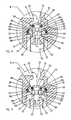
- FIG. 2 is a partial cross-section of an embodiment auto stop fluid valve in the open position.
- FIG. 3 is a partial cross-section of an embodiment auto stop fluid valve in the closed position.
- FIG. 4 is an enlarged circle 4 of FIG. 2 .
- FIG. 5 is an enlarged circle 5 of FIG. 3 .
- FIG. 1 is a perspective view of an embodiment drinking fountain 10 having an auto stop fluid valve. Visible in FIG. 1 is a drinking fountain body 11 with a basin extension 13 extending from the body. A basin 12 is at the top of the body and basin extension 13 . A bubbler 14 and a spigot 15 are visible extending above the basin 12 . A control button 16 is on the front of the basin extension 13 . The body is covered by a cover 21 . An access hole 18 is located on the underside of the basin extension 17 . Access hole 18 allows access to an auto stop fluid valve (not shown in FIG. 1 ) without requiring removal of the cover 21 . Louvers 20 for the cooling mechanism and an electrical cord 19 also are visible in FIG. 1 .
- FIG. 2 is a partial cross-section of an embodiment auto stop fluid valve 30 in the open position. Visible in FIG. 2 is the inlet body 45 which comprises an inlet port 32 , an inlet chamber 41 , and a valve chamber 35 .
- the inlet port 32 connects with a fluid or, in some embodiments such as drinking fountains, water supply.
- a poppet valve 59 is located between the inlet body 45 and the filter body 31 and allows passage of fluid from the inlet body to the filter body when in the open position (as in FIGS. 2 and 4 ) and blocks such passage when in the closed position (as in FIGS. 3 and 5 ).
- the poppet valve 59 is comprised of a poppet 50 and a retainer seat 36 . Circle 4 is shown in greater detail in FIG. 4 .
- a filter body 31 is attached to the inlet body 45 .
- the filter body 31 comprises a filter chamber 34 and a filter cap 60 .
- the filter cap 60 with a cap O-ring 65 is attached to and seals the bottom of the filter chamber 34 by cap threads 61 which interact with filter chamber threads 42 .
- the filter cap comprises a cap cavity 62 with a cavity bottom 63 and cavity side 64 .
- a slot 66 in the outside of the cap 60 interacts with and allows the rotation of the cap by a tool, such as a screwdriver or a vandal-resistant wrench.
- the fluid control chamber inlet port 47 provides fluid communication from the filter chamber 34 through the fluid control chamber wall 46 to the fluid control chamber 43 .
- a cylindrical filter 70 which has a second end 72 and a first end 71 is located in the filter chamber 34 .
- the second end 72 of the filter is in contact with the poppet 50 .
- the first end 71 of the filter is in contact with the cap cavity bottom 63 .
- a fluid control chamber body 40 is in fluid communication with the filter chamber 34 via fluid control chamber inlet port 47 through the fluid control chamber wall 46 .
- the fluid control chamber body 40 comprises fluid control chamber 43 , a fluid control chamber closure port 33 , and a fluid control chamber outlet port 48 through the fluid control chamber wall 46 .
- the fluid control chamber outlet port 48 is in fluid communication with the valve outlet port 49 .
- the valve outlet port 49 is connected to conduits for further use of the fluid, in embodiments, water.
- the fluid control chamber closure port 33 is normally closed by a threaded plug (not shown in FIG. 2 ).
- FIG. 2 shows the auto stop fluid valve 30 in the open position in which fluid flows through the valve from the valve inlet port 32 to the valve outlet port 49 .
- the cap 60 In this open position the cap 60 is in the upper position, as is the second end 72 of the filter 70 which bears upon and moves the poppet 50 in the poppet valve assembly 59 to the upper or open position.
- Arrows A-F depict the flow of fluid through the auto stop fluid valve. Fluid enters the valve inlet port 32 and enters the valve inlet chamber 35 as shown by arrow A.
- Arrow B shows the passage of fluid through the poppet 50 and arrow C shows the entry of fluid into the interior 73 of the filter 70 .
- Arrow D depicts movement of the fluid through the filter 70 into the filter chamber 34 .
- Arrows E show movement of the fluid from the filter chamber 34 into the fluid control chamber 43 , from which the fluid flows through the fluid control chamber outlet port 48 as depicted by arrow F, to the valve outlet port 49 for further use.
- FIG. 3 is a partial cross-section of an embodiment auto stop fluid valve 30 in the closed position. In this position the flow of fluid (shown by Arrow A) is stopped by the closed poppet valve assembly 59 at the valve chamber 35 and does not flow through the filter 70 or out of the auto stop fluid valve.
- the elements of FIG. 3 are the same as FIG. 1 with the exception of the position of the cap 60 , filter 70 and poppet 50 . Circle 5 is shown in greater detail in FIG. 5 .
- cap 60 In FIG. 3 the cap 60 is in the lower position. In this position the filter 70 is also in the lower position. When the filter 70 is in the lower position, pressure of fluid in the valve chamber 35 forces the poppet 50 into the lower position where it makes a sealing relationship with the poppet retainer seat 36 and blocks flow of fluid through the poppet valve assembly 59 .
- the cap 60 can be removed from the auto stop fluid valve 30 thereby allowing removal of the filter 70 for replacement or cleaning. Of course, removal of cap 60 also allows the poppet valve assembly 59 to close.
- FIG. 4 is an enlarged circle 4 of FIG. 2 . Visible in FIG. 4 is the valve inlet port 32 and valve inlet chamber 35 as well as the filter body 31 , filter chamber 34 , filter 70 , interior of filter 73 and second end 72 of filter. Details of the poppet valve assembly 59 in the open position are shown in FIG. 4 .
- the poppet 50 is comprised of a poppet cylinder 52 with a conical head 51 closing one end of the poppet cylinder 52 , one or more poppet cylinder flow passages 55 give access to the interior of the poppet cylinder 52 , and a poppet cylinder exit port 57 at the bottom of the cylinder allows fluid to flow into the interior 73 of the filter.
- a poppet cylinder O-ring groove 53 near the conical head 51 accommodates a poppet cylinder O-ring 54 .
- a poppet cylinder shoulder 56 is located about the circumference of the cylinder at the poppet cylinder exit port 57 .
- the poppet 50 is held in place by a donut-shaped retainer seat 36 attached at the top of the filter chamber 34 .
- the retainer seat 36 has a retainer seat sealing surface 38 .
- the retainer seat 36 has a retainer seat O-ring groove 37 about its circumference which accommodates a retainer seat O-ring 39 .
- Retaining ring 80 secures the poppet valve assembly 59 in place, in the upper end of the filter chamber 34 .
- FIG. 1 The flow of fluid through the poppet 50 and the filter 70 is shown by arrows A-D.
- Arrow A shows the flow of fluid through the valve inlet chamber 35
- arrow B shows the flow through poppet cylinder flow passages 55 in the poppet cylinder 52
- Arrow C shows emergence of fluid from the poppet cylinder exit port 57 into the interior 73 of the filter 70
- Arrow D shows flow of fluid through the filter 70 .
- FIG. 5 is an enlarged circle 5 of FIG. 3 .
- the flow of fluid shown by Arrow A
- FIG. 5 the poppet 50 has been moved by fluid pressure in the valve inlet chamber 35 from the open position shown in FIGS. 2 and 4 to the closed position shown in FIGS. 3 and 5 .
- the poppet cylinder flow passages 55 are closed or blocked by contact with the retainer seat 36 .
- the poppet 50 is further sealed by contact of the poppet cylinder O-ring 54 with the retainer seat sealing surface or shoulder 38 of the retainer seat 36 .
- the closing motion of the poppet is made possible by the movement of the second end 72 of the filter to the lower position, which in turn is made possible by the movement of the cap 60 (not shown in FIG. 5 ) to the lower position.
- the inlet body, poppet valve, filter body, and fluid control chamber body are manufactured of suitable strong, non-corrosive impervious material, for example, iron, stainless steel, copper, bronze, brass, aluminum, or plastic.
- the filter is woven or manufactured of a suitable strong insoluble, corrosion-resistant, material such as a ceramic, iron, stainless steel, copper, bronze, brass, aluminum, or plastic.
- the retaining ring is manufactured of suitable strong, insoluble, corrosion-resistant material, such as stainless steel, copper, bronze, brass or aluminum.
- Embodiments of auto stop fluid valves have a number of advantages. For example, maintenance of a water fountain generally begins with the step of turning off the supply of water. This is accomplished in fountains equipped with an auto stop valve by using a screwdriver or a vandal-resistant tool to move the cap from the upper to the lower position, thereby stopping the flow of water into the fountain. Similarly, when a fountain is turned off for any reason, one with a auto stop valve may easily be turned on by moving the cap to the upper position. This is accomplished without the necessity of removing any part of the fountain cover, thereby saving a substantial, often the major, amount of time required for the repair or maintenance of the water fountain. Once the water supply is turned off, the filter and or the fluid control cartridge can be removed and repaired or replaced without further removal of fountain elements.
Landscapes
- Engineering & Computer Science (AREA)
- General Engineering & Computer Science (AREA)
- Mechanical Engineering (AREA)
- Details Of Valves (AREA)
Abstract
Description
Claims (20)
Priority Applications (1)
| Application Number | Priority Date | Filing Date | Title |
|---|---|---|---|
| US13/507,454 US10100933B2 (en) | 2012-06-29 | 2012-06-29 | Auto stop fluid valve |
Applications Claiming Priority (1)
| Application Number | Priority Date | Filing Date | Title |
|---|---|---|---|
| US13/507,454 US10100933B2 (en) | 2012-06-29 | 2012-06-29 | Auto stop fluid valve |
Publications (2)
| Publication Number | Publication Date |
|---|---|
| US20140001279A1 US20140001279A1 (en) | 2014-01-02 |
| US10100933B2 true US10100933B2 (en) | 2018-10-16 |
Family
ID=49777088
Family Applications (1)
| Application Number | Title | Priority Date | Filing Date |
|---|---|---|---|
| US13/507,454 Active 2033-10-02 US10100933B2 (en) | 2012-06-29 | 2012-06-29 | Auto stop fluid valve |
Country Status (1)
| Country | Link |
|---|---|
| US (1) | US10100933B2 (en) |
Families Citing this family (2)
| Publication number | Priority date | Publication date | Assignee | Title |
|---|---|---|---|---|
| USD972679S1 (en) * | 2018-11-12 | 2022-12-13 | Haws Corporation | Combined water chiller, water fountain, and bottle filling station |
| USD995183S1 (en) * | 2021-08-17 | 2023-08-15 | Willoughby Industries Inc | Ligature resistant drinking fountain |
Citations (17)
| Publication number | Priority date | Publication date | Assignee | Title |
|---|---|---|---|---|
| US1407763A (en) | 1920-07-15 | 1922-02-28 | Wayne Oil Tank And Pump Compan | Filtering apparatus |
| US1927582A (en) * | 1931-01-21 | 1933-09-19 | Ralph G Denk | Combined filter and check valve |
| US2945591A (en) | 1956-09-20 | 1960-07-19 | Pall Corp | Filter |
| US4310142A (en) * | 1980-03-13 | 1982-01-12 | Tom Mcguane Industries, Inc. | Fuel pressure regulator assembly |
| US4329941A (en) * | 1981-01-30 | 1982-05-18 | Motohiro Niki | Water dispenser for small animals |
| US4439984A (en) * | 1981-07-20 | 1984-04-03 | Pall Corporation | Coaxial bidirectional spool valve |
| US4537350A (en) * | 1983-06-27 | 1985-08-27 | Apri Edward W | Self-actuating drinking fountain/faucet |
| US5611923A (en) | 1995-07-12 | 1997-03-18 | Vickers, Inc. | Filter assembly having quick connect/disconnect sealing valve means |
| US6899125B2 (en) * | 2002-03-01 | 2005-05-31 | Wagner Colora S.R.L. | Flow-adjusting device for a liquid, in particular a painting product |
| US6941893B2 (en) * | 2001-10-19 | 2005-09-13 | Lab Products, Inc. | Fluid delivery system |
| US20060000754A1 (en) | 2002-11-08 | 2006-01-05 | Won-Seok Kang | Water shut-off device for a water purifier |
| US7077153B2 (en) * | 2002-07-17 | 2006-07-18 | Newfrey Llc | Side control faucet with diverter assembly |
| US7090144B2 (en) * | 2003-10-30 | 2006-08-15 | Gross Lloyd A | Water fountain attachment for a faucet |
| US20070246567A1 (en) * | 2004-10-26 | 2007-10-25 | Roberts James C | Channeled check valve assembly |
| US20100170841A1 (en) * | 2009-01-07 | 2010-07-08 | Samsung Electronics Co., Ltd. | Filter assembly, valve assembly, and water purifying system having the same |
| US20110024344A1 (en) | 2009-08-03 | 2011-02-03 | Cummins Filtration Ip, Inc. | No filter no run fluid filtration system |
| US20110162734A1 (en) * | 2008-07-11 | 2011-07-07 | Colussi Rafael A | Pressure controlled three way valve device |
-
2012
- 2012-06-29 US US13/507,454 patent/US10100933B2/en active Active
Patent Citations (17)
| Publication number | Priority date | Publication date | Assignee | Title |
|---|---|---|---|---|
| US1407763A (en) | 1920-07-15 | 1922-02-28 | Wayne Oil Tank And Pump Compan | Filtering apparatus |
| US1927582A (en) * | 1931-01-21 | 1933-09-19 | Ralph G Denk | Combined filter and check valve |
| US2945591A (en) | 1956-09-20 | 1960-07-19 | Pall Corp | Filter |
| US4310142A (en) * | 1980-03-13 | 1982-01-12 | Tom Mcguane Industries, Inc. | Fuel pressure regulator assembly |
| US4329941A (en) * | 1981-01-30 | 1982-05-18 | Motohiro Niki | Water dispenser for small animals |
| US4439984A (en) * | 1981-07-20 | 1984-04-03 | Pall Corporation | Coaxial bidirectional spool valve |
| US4537350A (en) * | 1983-06-27 | 1985-08-27 | Apri Edward W | Self-actuating drinking fountain/faucet |
| US5611923A (en) | 1995-07-12 | 1997-03-18 | Vickers, Inc. | Filter assembly having quick connect/disconnect sealing valve means |
| US6941893B2 (en) * | 2001-10-19 | 2005-09-13 | Lab Products, Inc. | Fluid delivery system |
| US6899125B2 (en) * | 2002-03-01 | 2005-05-31 | Wagner Colora S.R.L. | Flow-adjusting device for a liquid, in particular a painting product |
| US7077153B2 (en) * | 2002-07-17 | 2006-07-18 | Newfrey Llc | Side control faucet with diverter assembly |
| US20060000754A1 (en) | 2002-11-08 | 2006-01-05 | Won-Seok Kang | Water shut-off device for a water purifier |
| US7090144B2 (en) * | 2003-10-30 | 2006-08-15 | Gross Lloyd A | Water fountain attachment for a faucet |
| US20070246567A1 (en) * | 2004-10-26 | 2007-10-25 | Roberts James C | Channeled check valve assembly |
| US20110162734A1 (en) * | 2008-07-11 | 2011-07-07 | Colussi Rafael A | Pressure controlled three way valve device |
| US20100170841A1 (en) * | 2009-01-07 | 2010-07-08 | Samsung Electronics Co., Ltd. | Filter assembly, valve assembly, and water purifying system having the same |
| US20110024344A1 (en) | 2009-08-03 | 2011-02-03 | Cummins Filtration Ip, Inc. | No filter no run fluid filtration system |
Also Published As
| Publication number | Publication date |
|---|---|
| US20140001279A1 (en) | 2014-01-02 |
Similar Documents
| Publication | Publication Date | Title |
|---|---|---|
| KR100804302B1 (en) | Filter cartridge coupling structure for water purifier | |
| US3327992A (en) | Control valves | |
| US4261545A (en) | Flush valve piston having filtered orifice | |
| US8469337B1 (en) | Faucet sealing | |
| US11186971B1 (en) | Auxiliary valve for hydrant | |
| MX2014003560A (en) | Mixing faucet provided with a filter. | |
| CN101018916A (en) | Outlet part with switchable jet regulator | |
| US10100933B2 (en) | Auto stop fluid valve | |
| JP3203739U (en) | Water purifier | |
| CA2869834C (en) | Rigid piston valve incorporating a solenoid | |
| KR20130014114A (en) | Air-exhaust check valve and storage tank having the same | |
| US20070278440A1 (en) | Faucet type valve with backflow control in handle structure | |
| JP3897619B2 (en) | Automatic water supply device | |
| KR20090081554A (en) | Water tap for water purifier | |
| US9367069B2 (en) | Pneumatic level switch | |
| SE510431C2 (en) | Diaphragm-controlled differential pressure valve | |
| US6863085B2 (en) | Faucet manifold assembly with in-line integral stops | |
| US4126296A (en) | Eccentric faucet insert | |
| US20070012361A1 (en) | Faucet co-operating with shower head | |
| JPH09264436A (en) | Switching valve and water purifier | |
| KR101098244B1 (en) | Stop valve for attachment of excavator | |
| JP6021194B2 (en) | Check valve for secondary side return water measures | |
| KR200383974Y1 (en) | Y-diaphragm valve | |
| JP6539820B2 (en) | On-off valve | |
| KR200493900Y1 (en) | multi-direction water faucet |
Legal Events
| Date | Code | Title | Description |
|---|---|---|---|
| AS | Assignment |
Owner name: ACORN ENGINEERING COMPANY, CALIFORNIA Free format text: ASSIGNMENT OF ASSIGNORS INTEREST;ASSIGNORS:BRIDGEFORD, BRANDON;YOUNG, DAVID;HAHN, RON;REEL/FRAME:028563/0394 Effective date: 20120621 |
|
| AS | Assignment |
Owner name: ACORN ENGINEERING COMPANY, CALIFORNIA Free format text: ASSIGNMENT OF ASSIGNORS INTEREST;ASSIGNORS:BRIDGEFORD, BRANDON;YOUNG, DAVID;HAHN, RON;REEL/FRAME:032065/0705 Effective date: 20120621 |
|
| STCF | Information on status: patent grant |
Free format text: PATENTED CASE |
|
| CC | Certificate of correction | ||
| MAFP | Maintenance fee payment |
Free format text: PAYMENT OF MAINTENANCE FEE, 4TH YEAR, LARGE ENTITY (ORIGINAL EVENT CODE: M1551); ENTITY STATUS OF PATENT OWNER: LARGE ENTITY Year of fee payment: 4 |
|
| MAFP | Maintenance fee payment |
Free format text: PAYMENT OF MAINTENANCE FEE, 8TH YEAR, LARGE ENTITY (ORIGINAL EVENT CODE: M1552); ENTITY STATUS OF PATENT OWNER: LARGE ENTITY Year of fee payment: 8 |