US10099852B2 - Corrugated steel floor in a shipping container - Google Patents
Corrugated steel floor in a shipping container Download PDFInfo
- Publication number
- US10099852B2 US10099852B2 US15/037,255 US201415037255A US10099852B2 US 10099852 B2 US10099852 B2 US 10099852B2 US 201415037255 A US201415037255 A US 201415037255A US 10099852 B2 US10099852 B2 US 10099852B2
- Authority
- US
- United States
- Prior art keywords
- floor
- container
- ridges
- steel floor
- slabs
- Prior art date
- Legal status (The legal status is an assumption and is not a legal conclusion. Google has not performed a legal analysis and makes no representation as to the accuracy of the status listed.)
- Active, expires
Links
- 229910000831 Steel Inorganic materials 0.000 title claims abstract description 48
- 239000010959 steel Substances 0.000 title claims abstract description 48
- 230000007797 corrosion Effects 0.000 claims description 7
- 238000005260 corrosion Methods 0.000 claims description 7
- 239000000463 material Substances 0.000 claims description 6
- 239000003973 paint Substances 0.000 claims description 3
- 239000000843 powder Substances 0.000 claims description 3
- 238000004381 surface treatment Methods 0.000 description 12
- XLYOFNOQVPJJNP-UHFFFAOYSA-N water Substances O XLYOFNOQVPJJNP-UHFFFAOYSA-N 0.000 description 10
- 238000003466 welding Methods 0.000 description 9
- 239000006260 foam Substances 0.000 description 4
- 230000002787 reinforcement Effects 0.000 description 4
- 238000000034 method Methods 0.000 description 3
- 239000000565 sealant Substances 0.000 description 3
- 230000007704 transition Effects 0.000 description 3
- 239000000853 adhesive Substances 0.000 description 2
- 238000004026 adhesive bonding Methods 0.000 description 2
- 230000001070 adhesive effect Effects 0.000 description 2
- 230000008901 benefit Effects 0.000 description 2
- 238000005219 brazing Methods 0.000 description 2
- 238000005304 joining Methods 0.000 description 2
- 239000011120 plywood Substances 0.000 description 2
- 230000000284 resting effect Effects 0.000 description 2
- 238000007789 sealing Methods 0.000 description 2
- 238000005476 soldering Methods 0.000 description 2
- 210000002105 tongue Anatomy 0.000 description 2
- 244000007853 Sarothamnus scoparius Species 0.000 description 1
- 239000011248 coating agent Substances 0.000 description 1
- 238000000576 coating method Methods 0.000 description 1
- 239000002131 composite material Substances 0.000 description 1
- 238000009713 electroplating Methods 0.000 description 1
- 238000009408 flooring Methods 0.000 description 1
- 238000004519 manufacturing process Methods 0.000 description 1
- 239000004033 plastic Substances 0.000 description 1
- 229920003023 plastic Polymers 0.000 description 1
- 239000012858 resilient material Substances 0.000 description 1
- 239000003566 sealing material Substances 0.000 description 1
- 230000003019 stabilising effect Effects 0.000 description 1
- 239000002436 steel type Substances 0.000 description 1
- 238000010408 sweeping Methods 0.000 description 1
- 239000013585 weight reducing agent Substances 0.000 description 1
- 239000002023 wood Substances 0.000 description 1
Images


Classifications
-
- B—PERFORMING OPERATIONS; TRANSPORTING
- B65—CONVEYING; PACKING; STORING; HANDLING THIN OR FILAMENTARY MATERIAL
- B65D—CONTAINERS FOR STORAGE OR TRANSPORT OF ARTICLES OR MATERIALS, e.g. BAGS, BARRELS, BOTTLES, BOXES, CANS, CARTONS, CRATES, DRUMS, JARS, TANKS, HOPPERS, FORWARDING CONTAINERS; ACCESSORIES, CLOSURES, OR FITTINGS THEREFOR; PACKAGING ELEMENTS; PACKAGES
- B65D90/00—Component parts, details or accessories for large containers
- B65D90/02—Wall construction
- B65D90/027—Corrugated or zig-zag structures; Folded plate
-
- B—PERFORMING OPERATIONS; TRANSPORTING
- B65—CONVEYING; PACKING; STORING; HANDLING THIN OR FILAMENTARY MATERIAL
- B65D—CONTAINERS FOR STORAGE OR TRANSPORT OF ARTICLES OR MATERIALS, e.g. BAGS, BARRELS, BOTTLES, BOXES, CANS, CARTONS, CRATES, DRUMS, JARS, TANKS, HOPPERS, FORWARDING CONTAINERS; ACCESSORIES, CLOSURES, OR FITTINGS THEREFOR; PACKAGING ELEMENTS; PACKAGES
- B65D90/00—Component parts, details or accessories for large containers
- B65D90/004—Contents retaining means
- B65D90/006—Contents retaining means fixed on the floor of the container
Definitions
- the invention relates to an element for a corrugated steel floor e.g. in a shipping container, which steel floor is positioned with corrugations running towards an opening for loading and unloading goods to be shipped or stored in the container.
- a shipping container usually comprises a pair of side walls, a rear end, a front end, a roof, a floor and a base frame.
- the base frame comprises two longitudinal bottom side rails and a plurality of parallel bottom cross members on which the floor is resting and to which cross members the floor is secured by fastening means.
- GB 2 406 560 In GB 2 406 560 is described a shipping container having a corrugated steel floor, which steel floor is welded to cross beams or cross members on which the floor is supported. The welding is performed in such a way that the welding seam is positioned under the corrugated floor.
- the stuffing can be made of wood, plastics or another preferably light material.
- a thin plate In combination with the corrugated steel floor, a thin plate can be paved on the corrugated steel floor.
- the thin plate may be made of thin wooden plate, composite plate or steel plate. Non-metallic stuffing may be filled within all the grooves of the corrugated steel floor in this embodiment too.
- a corrugated steel floor is often placed within a container in such a way that the ridges and grooves are positioned in a lengthwise direction of the container, in such a way that the ridges and grooves points towards a door or opening of the container.
- This is relevant for the possibility of emptying the grooves of the container floor from water or dirt and other such unwanted elements without need for special designed channels, grooves or pipes for emptying the grooves of the corrugations.
- Such special designed channels, grooves or pipes for emptying the grooves of the corrugations will be very difficult to clean and will most certainly be blocked by dirt or residues, but will be necessary in case the corrugations are positioned crosswise in the container.
- the object of the invention is to provide a corrugated steel floor making it possible that wheels from pallet trucks, pallet jacks, sack trolleys or similar equipment can roll relatively smooth on a corrugated steel floor without need for stuffing to fill up the grooves between the ridges and without need for an additional layer to be paved upon the corrugated steel floor.
- a corrugated steel floor according to the invention By a corrugated steel floor according to the invention the above disadvantages are avoided by having a corrugated steel floor where a distance between the ridges measured from a substantial vertical one side of a groove to a substantial vertical other side of the groove may be shorter than or equal to 40 mm.
- wheels from pallet trucks, pallet jacks, sack trolleys or similar equipment can roll relatively smooth on a corrugated steel floor without need for stuffing to fill up the grooves between the ridges.
- substantial vertical is meant between 85 and 95 degrees in relation to a horizontal direction.
- the grooves of the corrugations are flush with or placed on a door sill, making it possible to effectively emptying the grooves from water, dirt or other residues.
- the floor is assembled of a plurality of floor slabs making it possible to build up a floor of elements within the container.
- a length of a first side of a floor slab is shorter than a length of a second side of the floor slab, which difference corresponds to a material thickness of the floor slab, making it possible to join two floor slabs with an overlap and still have a level topside of the ridges relative to each other.
- the ridges of the corrugations are provided with a ramp, which ramp extends from a ridge to a level corresponding to the grooves.
- the ramp enforces the end of the ridges, preventing the corrugation from being flattened due to the weight from equipment loading and unloading the container.
- the floor slabs are coated before placing the slabs in the container.
- the floor slabs are galvanized.
- the floor slabs are coated with a corrosion protected layer
- the floor slabs are coated with powder paint.
- the floor slabs are fastened to a number of underlying cross members by fastening screws.
- the floor slabs are fastened to a number of underlying cross members by rivets.
- the floor slabs are fastened to a number of underlying cross members by mechanical fastening means such as adhesive, clamping, slot and groove or other suitable positive-fit connections.
- the floor slabs can be made from high strength steel.
- HTS high tensile steel can be used for manufacturing of the floor slabs.
- the floor slabs can be made of less material thickness and thereby the overall weight for the floor is reduced.
- lashing In containers with traditional plywood floors, securing of cargo, also called lashing, is accommodated by lashing rods/rings along bottom/top side rail, corner posts and headers.
- the plywood flooring can serve as mean for nailing in various combinations and patterns.
- attachment means for lashing In order to facilitate positioning and securing load or cargo within the container, different embodiments of attachment means for lashing can be provided.
- the purpose of the attachment means for lashing is to provide a fixed point for tying a rope, strap or similar fastening means holding load or cargo in a secured position to avoid damage on the cargo, other cargo shipped in the container or to the container itself.
- corrugated steel floor Given the nature of a corrugated steel floor, lashing by nailing into the floor is not an option. However, in order to accommodate potential extra lashing requirements the corrugated steel floor can be provided with alternatives to traditional lashing to the floor.
- Attachment means for lashing can be installed by attachment of rods, brackets or by other mechanical means in random positions in the corrugated floor in the container. It is possible to provide the floor with a combination of the above types of such attachment means for lashing.
- Further support blocks or chocks for stabilising the lashing of the cargo can be provided with ridges and grooves on their underside, which ridges and grooves corresponds to engagement with the corrugations in the floor.
- FIG. 1 shows schematically a container floor seen from above, inside the container
- FIG. 2 shows schematically a corrugated floor for a container
- FIG. 3 shows schematically a section of a corrugated floor for a container
- FIG. 4 shows schematically a section of a transition between the corrugated floor and a bottom side rail
- FIG. 5 shows schematically a section with a joining of two floor slabs
- FIG. 6 shows schematically a side view of a floor slab joined to a cross beam
- FIG. 7 shows schematically a section of a floor slab seen from an end with a ramp
- FIG. 8 shows schematically the section from FIG. 7 seen from a side
- FIG. 9 shows schematically the section from FIG. 7 seen from above
- FIG. 10 shows schematically the section from FIGS. 7 to 9 in a perspective view
- FIG. 11 shows schematically a section of a floor slab placed on a cross member of heavy dimension
- FIG. 12 shows schematically a section of a door sill provided with ramps and a floor slab abutting the door sill and ramps;
- FIG. 13 shows schematically a container with open doors, showing an example of a position for attachment means for lashing
- FIG. 14 shows schematically an attachment means for lashing positioned as indicated in FIG. 13 ;
- FIG. 15 shows schematically an alternative attachment means for lashing positioned as indicated in FIG. 13 ;
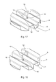
- FIG. 16 shows schematically an alternative attachment means for lashing positioned as indicated in FIG. 13 ;
- FIG. 17 shows schematically an alternative attachment means for lashing positioned as indicated in FIG. 13 ;
- FIG. 18 shows schematically an alternative attachment means for lashing positioned as indicated in FIG. 13 ;
- FIG. 19 shows schematically an alternative attachment means for lashing positioned as indicated in FIG. 13 .
- a shipping container 20 usually comprises a pair of side walls, a rear end, a front end, a roof, a floor 1 and a base frame 2 .
- the base frame 2 comprises two longitudinal bottom side rails 3 and a plurality of parallel bottom cross members 4 on which the floor 1 is resting and to which cross members 4 the floor 1 is secured by fastening means 5 .
- the container is provided with an opening 21 for loading and unloading goods to be shipped or stored in the container 20 .
- the steel floor 1 is positioned with corrugations comprising a number of ridges 6 and grooves 7 running towards an opening for loading and unloading goods to be shipped or stored in the container 20 .
- the purpose of the floor 1 is to support items (not shown) to be shipped within the container 20 and to form a sufficient base for equipment handling the items when loading and unloading the container 20 .
- equipment can for example be a pallet truck or a pallet jack (not shown), but common to such equipment is that the equipment, which is most often provided with wheels, is intended to roll on a stable surface within the container 20 .
- the grooves 7 are usually filled with stuffing making it possible that wheels from pallet trucks, pallet jacks, sack trolleys or similar equipment can roll relatively smooth on a corrugated steel floor.
- the corrugated steel floor according to the invention is dimensioned in such a way that it is not necessary to make use of stuffing in the grooves 7 . This is achieved with a corrugated steel floor 1 , where a distance between the ridges 6 measured from a substantial vertical one side 8 of a groove 7 to a substantial vertical other side 9 of the groove is shorter than or equal to 40 mm.
- the distance between the ridges 6 measured from a substantial vertical one side 8 of a groove 7 to a substantial vertical other side 9 of the groove is shorter than or equal to 35 mm.
- the distance between the ridges 6 measured from a substantial vertical one side 8 of a groove 7 to a substantial vertical other side 9 of the groove is shorter than or equal to 32.5 mm.
- wheels from pallet trucks, pallet jacks, sack trolleys or similar equipment can roll relatively smooth on a corrugated steel floor 1 without need for stuffing to fill up the grooves 7 between the ridges 6 .
- the grooves 7 of the corrugations are flush with or placed on a door sill 14 , making it possible to effectively emptying the grooves 7 from water, dirt or other residues.
- the floor 1 is assembled of a plurality of floor slabs 10 making it possible to build up a floor 1 of elements within the container 20 .
- a height of a first side 11 of a floor slab 10 is less than a height of a second side 12 of the floor slab 10 , which difference corresponds to a material thickness of the floor slab 10 , making it possible to join two floor slabs 10 with an overlap and still have a level topside of the ridges 6 relative to each other.
- the ridges 6 of the corrugations are provided with a ramp 13 , which ramp 13 inclines from a ridge 6 to a level corresponding to the grooves 7 .
- the ramp 13 enforces the end of the ridges 6 , preventing the corrugation from being flattened due to the weight from equipment loading and unloading the container 20 .
- the floor slabs 10 are coated before placing the slabs 10 in the container 20 .
- the floor slabs 10 are galvanized.
- the floor slabs 10 are coated with a corrosion protected layer
- the floor slabs 10 are coated with powder paint.
- the floor 1 can be assembled by floor slabs 10 extending over the entire length of the container 20 .
- Floor slabs 10 can also be dimensioned to cover a part of the length, but floor slabs 10 extending substantially over the entire length of the container 20 is preferred.
- the floor 1 or floor slabs 10 can be fastened to a number of underlying cross members 4 by mechanical fastening means such as adhesive, clamping, slot and groove etc.
- the slot and groove can be realised by a raised tongue fitting into a slit positioned on a floor slab 10 and to a cross member 4 respectively or a similar positive-fit connection.
- rivets or other mechanical removable fastening means can hold the floor and secure against relative horizontal movement between floor and cross member while the positive-fit connection prevents relative vertical movement between floor and cross member.
- the ramps 13 is secured to the door sill 14 in such a way that one end of the floor slabs 10 can be positioned at the end of the floor 1 pointing towards the opening for loading and unloading goods to be shipped or stored in the container 20 , where the ridges 6 of the corrugations are positioned abutting the ramp 13 , which ramp 13 inclines from a ridge 6 to a level corresponding to the grooves 7 and thereby forming a floor, where the ridges 6 of the floor slabs are substantially flush with ridges of the ramps 13 .
- the ramps 13 are secured to the door sill 14 by welding.
- the part of the ramps pointing towards the opening of the container 20 is welded along a majority of the entire length of the ramps, preferably along the entire length.
- the ramps 13 are welded in spots situated behind the tops or ridges 6 of the ramps 13 . Thereby the welding seam will not block for positioning the lower part being the grooves 7 of the corrugated floor slabs 10 on the door sill 14 abutting the ramps 13 .
- a floor slab 10 of the corrugated floor 1 at the end of the floor 1 pointing towards the opening 21 for loading and unloading goods to be shipped or stored in the container 20 , is provided with ramps 13 .
- the floor slab 10 is positioned in the right direction thereby ensuring that the overlap will be placed correctly so that the assembled floor 1 will have the same height and the upper side of the ridges 6 of the floor 1 is level.
- cross members 40 are positioned with their upper surfaces substantially flush with the rest of the cross members 4 thereby providing a plane support for the floor 1 and making it possible that the corrugations can run continuously from one end of the container 20 to the other end of the container 20 .
- the cross members 4 , 40 or the floor slabs 10 are arranged in such a way that they are sloping slightly in direction of the opening 21 end of the container 20 to be able to facilitate emptying of the grooves 7 in the corrugated floor slabs 10 .
- an area in the middle section or full width can be substituted by a plane surface, level with the upper part of the corrugations—the ridges 6 —to make room for reinforcement or other space consuming elements beneath the floor.
- the ends of the corrugations of the floor slabs 10 abutting the plane surface are closed in such a way that water or dirt cannot escape from the grooves 7 through openings.
- the plane surface can be provided with a substantially vertical or downwards slanting edge, forming an end wall in the corrugated floor slab abutting the edge of the plane surface. If the edge is slanting downwards, its profile should correspond to the corrugations of the floor slab 10 .
- the floor slabs 10 are provided with blocks and/or sealant, filling out gaps between floor slabs 10 and cross members 4 , 40 , preventing water from entering from below the floor 1 .
- the sealant can be foam, gum or other suitable material.
- sealant between joining of the floor slabs 10 prevents water from entering the container 20 from below.
- attachment means 15 for lashing can be provided.
- the purpose of the attachment means 15 for lashing is to provide a fixed point for tying a rope, strap or similar fastening means (not shown) holding load or cargo in a secured position to avoid damage on the cargo, other cargo shipped in the container or to the container 20 itself.
- corrugated steel floor 1 Given the nature of a corrugated steel floor 1 , lashing by nailing into the floor is not an option. However, in order to accommodate potential extra lashing requirements the corrugated steel floor 1 can be provided with alternatives to traditional lashing to the floor.
- Attachment means 15 for lashing can be installed by attachment of rods, brackets or by other mechanical means in random positions in the corrugated floor 1 in the container 20 .
- Attachment means 15 for lashing can be provided by a rod or pin ( FIG. 14 ) fixed in holes 16 in the substantial vertical sides 8 , 9 of the ridges 6 in the corrugated floor 1 .
- the rod or pin can be fixed by welding, soldering, brazing, gluing or other known fixing methods, It is possible to fix the rod in the holes in the ridges 6 before the floor slabs 10 are positioned in the container 20 , which makes it possible to coat or provide the floor slab 10 with a surface treatment preventing corrosion after fixing the rod to the floor slab 10 .
- the rod or pin can be positioned in the holes in the substantial vertical sides of the ridges 6 and held in place by a foam block, which foam block is shaped to fit in the underside of a ridge. Thereby the foam block acts both as a member holding the rod or pin in place in the floor and as a sealing means preventing water from entering the container from the underside.
- Other suitable and similar resilient and sealing materials can be used.
- Attachment means 15 for lashing can be provided by a piece of a square or rectangular tube in which an opening 17 is cut in a middle portion of an upper surface of the tube ( FIG. 15 ).
- the tube is positioned in a groove 7 between two ridges 6 and the tube can be fixed by welding, soldering, brazing, gluing or other known fixing methods, It is possible to fix the tube in the groove 7 before the floor slabs 10 are positioned in the container 20 , which makes it possible to coat or provide the floor slab 10 with a surface treatment preventing corrosion after fixing the rod to the floor slab 10 .
- the tube can also be fixed with the floor slab 10 positioned in the container 20 .
- Attachment means 15 for lashing can be provided by a bracket having two parallel portions, which parallel portions are connected in one end by a connection portion 19 and at the opposite free end the parallel portions are bended into an outgoing direction in order to engage with holes 16 in the substantial vertical sides 8 , 9 of a ridge 6 in the corrugated floor 1 .
- An alternative bracket for lashing ( FIG. 17 ) can be provided by two converging portions, which portions are connected by a connection portion 19 in the end having the widest distance from each other and at the opposite free end the converging portions are bended into an outgoing direction ( FIG. 16 ) in order to engage with holes 16 in the substantial vertical sides 8 , 9 of the ridges 6 in the corrugated floor 1 .
- the connecting portion 19 is preferably longer than the width of the groove 7 .
- An alternative bracket for lashing ( FIG. 18 ) can be provided by a bracket having two parallel portions, which parallel portions are connected in one end by a connection portion 19 and at the opposite free end the parallel portions are bended towards each other in an ingoing direction in order to engage with holes 16 in the substantial vertical sides 8 , 9 of a ridge 6 in the corrugated floor 1 ,
- An alternative bracket for lashing ( FIG. 19 ) can be provided by a bracket having two parallel portions, which parallel portions are connected in one end by a connection portion 19 , which connection portion is longer than the width of a groove 7 , At the opposite free end the parallel portions are bended into an outgoing direction in order to engage with holes 16 in the substantial vertical sides 8 , 9 of a ridge 6 in the corrugated floor 1 .
- the length of the bracket corresponds to a distance a bit longer than the distance corresponding to the width of two grooves and one ridge in order to let the free ends of the bracket engage in the holes 16 in the substantial vertical sides 8 , 9 of ridges 6 .
- the brackets can be fixed with the floor slab 10 positioned in the container 20 .
- the holes 16 in the ridges 6 can be made before profiling the floor slab 10 or the holes 16 can be provided after profiling the floor slab 10 before the floor slabs 10 are positioned in the container 20 , which makes it possible to coat or provide the floor slab 10 with a surface treatment preventing corrosion after providing the hole 16 in the floor slab 10 .
- a bushing or reinforcement disc 18 can be inserted in the hole 16 , thereby reducing wear from the bracket due to stress caused by the lashed cargo.
- the bushing or reinforcement disc 18 can also be provided with sealing means preventing water from passing through the hole where the bushing or reinforcement disc 18 is placed in the floor 1 .
Landscapes
- Engineering & Computer Science (AREA)
- Mechanical Engineering (AREA)
- Pallets (AREA)
Abstract
The invention relates to a corrugated steel floor (1) in a shipping container (20), which steel floor (1) is positioned with corrugations comprising a number of ridges (6) and grooves (7) running towards an opening (21) for loading and unloading goods to be shipped or stored in the container (20), where a distance between the ridges (6) measured from a substantial vertical one side (8) of a groove (7) to a substantial vertical other side (9) of the groove (7) is shorter than or equal to 40 mm. Further the grooves (7) of the corrugations are flush with or placed on a door sill (14) and the floor (1) can be assembled of a plurality of floor slabs (10). Further the floor (1) can be provided with lashing means.
Description
This application claims the benefit under 35 U.S.C. § 371 of the filing date of International Patent Application No. PCT/EP2014/074259, having an international filing date of Nov. 11, 2014, which claims priority to Danish Application No. DK PA201370699, filed Nov. 18, 2013, the contents of both of which are incorporated herein by reference in their entirety.
The invention relates to an element for a corrugated steel floor e.g. in a shipping container, which steel floor is positioned with corrugations running towards an opening for loading and unloading goods to be shipped or stored in the container.
A shipping container usually comprises a pair of side walls, a rear end, a front end, a roof, a floor and a base frame. The base frame comprises two longitudinal bottom side rails and a plurality of parallel bottom cross members on which the floor is resting and to which cross members the floor is secured by fastening means.
In GB 2 406 560 is described a shipping container having a corrugated steel floor, which steel floor is welded to cross beams or cross members on which the floor is supported. The welding is performed in such a way that the welding seam is positioned under the corrugated floor.
Some disadvantages relating to such a solution to be mentioned are the difficulty in mounting the floor within the container. The floor must be assembled to the cross members before entering the container or the floor must be welded to the cross members while a welder is placed in an upright position for example in a pit beneath the container or the container is elevated to make room for a person standing or sitting under the container. Further it is not desirable to weld on a steel floor applied with a kind of surface treatment to prolong the life of the floor. Such a procedure will burn off the surface treatment being paintwork, galvanisation or electroplating. If welded to cross members the surface treatment of cross members is damaged as well. If postponing the surface treatment till after welding there will be overlapping areas between cross members and floor where no coating is applied. Further the assembled floor section will be difficult to handle if the assembled floor section should be provided with surface treatment.
Another disadvantage relating to known corrugated steel floors is that to ensure proper handling of pallets or other kind of goods to be positioned by pallet trucks or pallet jacks, “valleys” formed by grooves between ridges in the corrugated floor are filled by stuffing, which stuffing is dimensioned to ensure a level floor with no difference in height. Hereby wheels from pallet trucks or pallet jacks can roll relatively smooth on the floor.
Several known corrugated floors making use of stuffing to fill up the grooves between the ridges are manufactured with wide ridges to bring down the weight of the corrugated steel floor.
The stuffing can be made of wood, plastics or another preferably light material.
In combination with the corrugated steel floor, a thin plate can be paved on the corrugated steel floor. The thin plate may be made of thin wooden plate, composite plate or steel plate. Non-metallic stuffing may be filled within all the grooves of the corrugated steel floor in this embodiment too.
Further a corrugated steel floor is often placed within a container in such a way that the ridges and grooves are positioned in a lengthwise direction of the container, in such a way that the ridges and grooves points towards a door or opening of the container. This is relevant for the possibility of emptying the grooves of the container floor from water or dirt and other such unwanted elements without need for special designed channels, grooves or pipes for emptying the grooves of the corrugations. Such special designed channels, grooves or pipes for emptying the grooves of the corrugations will be very difficult to clean and will most certainly be blocked by dirt or residues, but will be necessary in case the corrugations are positioned crosswise in the container.
It is known to have corrugated floors within a container where the top of the ridges are level with a door sill. This requires that the above mentioned water, dirt or other residues can be led to a transition between the corrugated floor and the door sill where water, dirt or other residues can be led out of the container. This can be done by manually sweeping the transition with a broom or another suitable tool.
The object of the invention is to provide a corrugated steel floor making it possible that wheels from pallet trucks, pallet jacks, sack trolleys or similar equipment can roll relatively smooth on a corrugated steel floor without need for stuffing to fill up the grooves between the ridges and without need for an additional layer to be paved upon the corrugated steel floor.
By a corrugated steel floor according to the invention the above disadvantages are avoided by having a corrugated steel floor where a distance between the ridges measured from a substantial vertical one side of a groove to a substantial vertical other side of the groove may be shorter than or equal to 40 mm.
Hereby is achieved that wheels from pallet trucks, pallet jacks, sack trolleys or similar equipment can roll relatively smooth on a corrugated steel floor without need for stuffing to fill up the grooves between the ridges.
By substantial vertical is meant between 85 and 95 degrees in relation to a horizontal direction.
According to an aspect of the solution the grooves of the corrugations are flush with or placed on a door sill, making it possible to effectively emptying the grooves from water, dirt or other residues.
In another aspect the floor is assembled of a plurality of floor slabs making it possible to build up a floor of elements within the container.
In another aspect a length of a first side of a floor slab is shorter than a length of a second side of the floor slab, which difference corresponds to a material thickness of the floor slab, making it possible to join two floor slabs with an overlap and still have a level topside of the ridges relative to each other.
In another aspect the corrugated floor at an end of the floor pointing towards the opening for loading and unloading goods to be shipped or stored in the container, the ridges of the corrugations are provided with a ramp, which ramp extends from a ridge to a level corresponding to the grooves.
Hereby is facilitated easy and convenient access to the interior of the container for pallet trucks, pallet jacks, sack trolleys or similar equipment without need for overcoming a high sharp edge.
Further is achieved that the ramp enforces the end of the ridges, preventing the corrugation from being flattened due to the weight from equipment loading and unloading the container.
In another aspect the floor slabs are coated before placing the slabs in the container.
In another aspect the floor slabs are galvanized.
In another aspect the floor slabs are coated with a corrosion protected layer
In another aspect the floor slabs are coated with powder paint.
In another aspect the floor slabs are fastened to a number of underlying cross members by fastening screws.
In another aspect the floor slabs are fastened to a number of underlying cross members by rivets.
In another aspect the floor slabs are fastened to a number of underlying cross members by mechanical fastening means such as adhesive, clamping, slot and groove or other suitable positive-fit connections.
These aspects relating to surface treatment of the floor slabs ensures a longer lifetime to the floor slabs.
The floor slabs can be made from high strength steel. As an example HTS high tensile steel can be used for manufacturing of the floor slabs. When using a steel type with higher strength, the floor slabs can be made of less material thickness and thereby the overall weight for the floor is reduced.
Further fewer cross members are necessary, which leads to further weight reduction.
In containers with traditional plywood floors, securing of cargo, also called lashing, is accommodated by lashing rods/rings along bottom/top side rail, corner posts and headers. In case of special cargo which require extra lashing, the plywood flooring can serve as mean for nailing in various combinations and patterns.
In order to facilitate positioning and securing load or cargo within the container, different embodiments of attachment means for lashing can be provided. The purpose of the attachment means for lashing is to provide a fixed point for tying a rope, strap or similar fastening means holding load or cargo in a secured position to avoid damage on the cargo, other cargo shipped in the container or to the container itself.
Given the nature of a corrugated steel floor, lashing by nailing into the floor is not an option. However, in order to accommodate potential extra lashing requirements the corrugated steel floor can be provided with alternatives to traditional lashing to the floor.
Attachment means for lashing can be installed by attachment of rods, brackets or by other mechanical means in random positions in the corrugated floor in the container. It is possible to provide the floor with a combination of the above types of such attachment means for lashing.
Further support blocks or chocks for stabilising the lashing of the cargo can be provided with ridges and grooves on their underside, which ridges and grooves corresponds to engagement with the corrugations in the floor.
Further embodiments and advantages are disclosed below in the description and in the claims.
The invention will now be described more fully below, by way of example only, with reference to the accompanying drawings, in which
Now convenient embodiments of the invention will be described.
A shipping container 20 usually comprises a pair of side walls, a rear end, a front end, a roof, a floor 1 and a base frame 2. The base frame 2 comprises two longitudinal bottom side rails 3 and a plurality of parallel bottom cross members 4 on which the floor 1 is resting and to which cross members 4 the floor 1 is secured by fastening means 5. The container is provided with an opening 21 for loading and unloading goods to be shipped or stored in the container 20.
The steel floor 1 is positioned with corrugations comprising a number of ridges 6 and grooves 7 running towards an opening for loading and unloading goods to be shipped or stored in the container 20.
The purpose of the floor 1 is to support items (not shown) to be shipped within the container 20 and to form a sufficient base for equipment handling the items when loading and unloading the container 20. Such equipment can for example be a pallet truck or a pallet jack (not shown), but common to such equipment is that the equipment, which is most often provided with wheels, is intended to roll on a stable surface within the container 20.
When using a corrugated steel floor 1 in a container 20, which corrugated steel floor 1 comprises a number of ridges 6 and grooves 7, the grooves 7 are usually filled with stuffing making it possible that wheels from pallet trucks, pallet jacks, sack trolleys or similar equipment can roll relatively smooth on a corrugated steel floor.
The corrugated steel floor according to the invention is dimensioned in such a way that it is not necessary to make use of stuffing in the grooves 7. This is achieved with a corrugated steel floor 1, where a distance between the ridges 6 measured from a substantial vertical one side 8 of a groove 7 to a substantial vertical other side 9 of the groove is shorter than or equal to 40 mm.
In an alternative embodiment the distance between the ridges 6 measured from a substantial vertical one side 8 of a groove 7 to a substantial vertical other side 9 of the groove is shorter than or equal to 35 mm.
In yet an alternative embodiment the distance between the ridges 6 measured from a substantial vertical one side 8 of a groove 7 to a substantial vertical other side 9 of the groove is shorter than or equal to 32.5 mm.
Hereby is achieved that wheels from pallet trucks, pallet jacks, sack trolleys or similar equipment can roll relatively smooth on a corrugated steel floor 1 without need for stuffing to fill up the grooves 7 between the ridges 6.
According to an aspect of the solution the grooves 7 of the corrugations are flush with or placed on a door sill 14, making it possible to effectively emptying the grooves 7 from water, dirt or other residues.
In another aspect the floor 1 is assembled of a plurality of floor slabs 10 making it possible to build up a floor 1 of elements within the container 20.
In another aspect a height of a first side 11 of a floor slab 10 is less than a height of a second side 12 of the floor slab 10, which difference corresponds to a material thickness of the floor slab 10, making it possible to join two floor slabs 10 with an overlap and still have a level topside of the ridges 6 relative to each other.
In another aspect the corrugated floor 1 at an end of the floor pointing towards the opening for loading and unloading goods to be shipped or stored in the container 20, the ridges 6 of the corrugations are provided with a ramp 13, which ramp 13 inclines from a ridge 6 to a level corresponding to the grooves 7.
Hereby is facilitated easy and convenient access to the interior of the container 20 for pallet trucks, pallet jacks, sack trolleys or similar equipment without need for overcoming a high sharp edge.
Further is achieved that the ramp 13 enforces the end of the ridges 6, preventing the corrugation from being flattened due to the weight from equipment loading and unloading the container 20.
In another aspect the floor slabs 10 are coated before placing the slabs 10 in the container 20.
In another aspect the floor slabs 10 are galvanized.
In another aspect the floor slabs 10 are coated with a corrosion protected layer
In another aspect the floor slabs 10 are coated with powder paint.
These aspects relating to surface treatment of the floor slabs 10 ensures a longer lifetime to the floor slabs 10.
The floor 1 can be assembled by floor slabs 10 extending over the entire length of the container 20.
By assembling the floor 1 by floor slabs 10 fastened by screws, rivets or other mechanical fastening means 5 to the cross members 4, it is possible to provide the floor slabs 10 with a surface treatment, which is not damaged by welding as if the floor was welded to the cross members 4. Also damage to cross member surface treatment due to welding is avoided.
The floor 1 or floor slabs 10 can be fastened to a number of underlying cross members 4 by mechanical fastening means such as adhesive, clamping, slot and groove etc. The slot and groove can be realised by a raised tongue fitting into a slit positioned on a floor slab 10 and to a cross member 4 respectively or a similar positive-fit connection. When floor and cross members is translated relative to each other the tongues are engaging with the slits and a few screws, rivets or other mechanical removable fastening means can hold the floor and secure against relative horizontal movement between floor and cross member while the positive-fit connection prevents relative vertical movement between floor and cross member.
Further it is easy to replace one or more floor slabs 10 if a part of the floor 1 should be damaged.
In another aspect the ramps 13 is secured to the door sill 14 in such a way that one end of the floor slabs 10 can be positioned at the end of the floor 1 pointing towards the opening for loading and unloading goods to be shipped or stored in the container 20, where the ridges 6 of the corrugations are positioned abutting the ramp 13, which ramp 13 inclines from a ridge 6 to a level corresponding to the grooves 7 and thereby forming a floor, where the ridges 6 of the floor slabs are substantially flush with ridges of the ramps 13.
In an embodiment the ramps 13 are secured to the door sill 14 by welding. Here the part of the ramps pointing towards the opening of the container 20 is welded along a majority of the entire length of the ramps, preferably along the entire length.
On the rear side of the ramps 13 or the side pointing away from the opening 21 of the container 20, the ramps 13 are welded in spots situated behind the tops or ridges 6 of the ramps 13. Thereby the welding seam will not block for positioning the lower part being the grooves 7 of the corrugated floor slabs 10 on the door sill 14 abutting the ramps 13.
In an alternative embodiment a floor slab 10 of the corrugated floor 1, at the end of the floor 1 pointing towards the opening 21 for loading and unloading goods to be shipped or stored in the container 20, is provided with ramps 13. Hereby it is easy to see if the floor slab 10 is positioned in the right direction thereby ensuring that the overlap will be placed correctly so that the assembled floor 1 will have the same height and the upper side of the ridges 6 of the floor 1 is level.
In case it is necessary to have one or more cross beams or cross members 40 of a heavier dimension than the rest of the cross members 4, such cross members 40 are positioned with their upper surfaces substantially flush with the rest of the cross members 4 thereby providing a plane support for the floor 1 and making it possible that the corrugations can run continuously from one end of the container 20 to the other end of the container 20.
In an advantageous embodiment, the cross members 4, 40 or the floor slabs 10 are arranged in such a way that they are sloping slightly in direction of the opening 21 end of the container 20 to be able to facilitate emptying of the grooves 7 in the corrugated floor slabs 10.
In the end of the floor pointing away from the container opening 21 an area in the middle section or full width can be substituted by a plane surface, level with the upper part of the corrugations—the ridges 6—to make room for reinforcement or other space consuming elements beneath the floor.
The ends of the corrugations of the floor slabs 10 abutting the plane surface are closed in such a way that water or dirt cannot escape from the grooves 7 through openings. The plane surface can be provided with a substantially vertical or downwards slanting edge, forming an end wall in the corrugated floor slab abutting the edge of the plane surface. If the edge is slanting downwards, its profile should correspond to the corrugations of the floor slab 10.
In both ends of the floor, the floor slabs 10 are provided with blocks and/or sealant, filling out gaps between floor slabs 10 and cross members 4, 40, preventing water from entering from below the floor 1. The sealant can be foam, gum or other suitable material.
Also sealant between joining of the floor slabs 10 prevents water from entering the container 20 from below.
In order to facilitate positioning and securing load or cargo within the container 20, different embodiments of attachment means 15 for lashing can be provided. The purpose of the attachment means 15 for lashing is to provide a fixed point for tying a rope, strap or similar fastening means (not shown) holding load or cargo in a secured position to avoid damage on the cargo, other cargo shipped in the container or to the container 20 itself.
Given the nature of a corrugated steel floor 1, lashing by nailing into the floor is not an option. However, in order to accommodate potential extra lashing requirements the corrugated steel floor 1 can be provided with alternatives to traditional lashing to the floor.
Attachment means 15 for lashing can be installed by attachment of rods, brackets or by other mechanical means in random positions in the corrugated floor 1 in the container 20.
Attachment means 15 for lashing can be provided by a rod or pin (FIG. 14 ) fixed in holes 16 in the substantial vertical sides 8, 9 of the ridges 6 in the corrugated floor 1. The rod or pin can be fixed by welding, soldering, brazing, gluing or other known fixing methods, It is possible to fix the rod in the holes in the ridges 6 before the floor slabs 10 are positioned in the container 20, which makes it possible to coat or provide the floor slab 10 with a surface treatment preventing corrosion after fixing the rod to the floor slab 10. In an alternative, the rod or pin can be positioned in the holes in the substantial vertical sides of the ridges 6 and held in place by a foam block, which foam block is shaped to fit in the underside of a ridge. Thereby the foam block acts both as a member holding the rod or pin in place in the floor and as a sealing means preventing water from entering the container from the underside. Other suitable and similar resilient and sealing materials can be used.
Attachment means 15 for lashing can be provided by a piece of a square or rectangular tube in which an opening 17 is cut in a middle portion of an upper surface of the tube (FIG. 15 ). The tube is positioned in a groove 7 between two ridges 6 and the tube can be fixed by welding, soldering, brazing, gluing or other known fixing methods, It is possible to fix the tube in the groove 7 before the floor slabs 10 are positioned in the container 20, which makes it possible to coat or provide the floor slab 10 with a surface treatment preventing corrosion after fixing the rod to the floor slab 10. The tube can also be fixed with the floor slab 10 positioned in the container 20.
Attachment means 15 for lashing (FIG. 16 ) can be provided by a bracket having two parallel portions, which parallel portions are connected in one end by a connection portion 19 and at the opposite free end the parallel portions are bended into an outgoing direction in order to engage with holes 16 in the substantial vertical sides 8, 9 of a ridge 6 in the corrugated floor 1.
An alternative bracket for lashing (FIG. 17 ) can be provided by two converging portions, which portions are connected by a connection portion 19 in the end having the widest distance from each other and at the opposite free end the converging portions are bended into an outgoing direction (FIG. 16 ) in order to engage with holes 16 in the substantial vertical sides 8, 9 of the ridges 6 in the corrugated floor 1. The connecting portion 19 is preferably longer than the width of the groove 7.
An alternative bracket for lashing (FIG. 18 ) can be provided by a bracket having two parallel portions, which parallel portions are connected in one end by a connection portion 19 and at the opposite free end the parallel portions are bended towards each other in an ingoing direction in order to engage with holes 16 in the substantial vertical sides 8, 9 of a ridge 6 in the corrugated floor 1,
An alternative bracket for lashing (FIG. 19 ) can be provided by a bracket having two parallel portions, which parallel portions are connected in one end by a connection portion 19, which connection portion is longer than the width of a groove 7, At the opposite free end the parallel portions are bended into an outgoing direction in order to engage with holes 16 in the substantial vertical sides 8, 9 of a ridge 6 in the corrugated floor 1. Preferably the length of the bracket corresponds to a distance a bit longer than the distance corresponding to the width of two grooves and one ridge in order to let the free ends of the bracket engage in the holes 16 in the substantial vertical sides 8, 9 of ridges 6.
The brackets can be fixed with the floor slab 10 positioned in the container 20.
The holes 16 in the ridges 6 can be made before profiling the floor slab 10 or the holes 16 can be provided after profiling the floor slab 10 before the floor slabs 10 are positioned in the container 20, which makes it possible to coat or provide the floor slab 10 with a surface treatment preventing corrosion after providing the hole 16 in the floor slab 10.
It is also possible to provide the hole after the floor slab 10 is positioned in the container 20 and optionally provide the hole 16 with an after treatment preventing corrosion after providing the hole 16 in the floor slab 10.
To avoid damage to the hole 16, a bushing or reinforcement disc 18 can be inserted in the hole 16, thereby reducing wear from the bracket due to stress caused by the lashed cargo. The bushing or reinforcement disc 18 can also be provided with sealing means preventing water from passing through the hole where the bushing or reinforcement disc 18 is placed in the floor 1.
Claims (12)
1. A corrugated steel floor for a shipping container comprising:
a plurality of steel floor slabs that collectively span a width of the shipping container in at least a part of the shipping container,
wherein each steel floor slab is corrugated so that ridges and grooves of the steel floor slab run towards an opening of the shipping container to facilitate loading and unloading goods to be shipped or stored in the container,
wherein a distance between the ridges measured from a substantial vertical one side of a groove to a substantial vertical other side of the groove is shorter than or equal to 40 mm;
wherein the bottom of the grooves of the corrugations are flush with or placed on a door sill at an end of the floor pointing towards the opening for loading and unloading goods to be shipped or stored in the container; and
wherein each of the ridges of the corrugations includes a ramp that inclines towards the opening from a portion of the ridge disposed on the door sill to a level on the door sill corresponding to a level of the grooves.
2. The floor according to claim 1 , wherein a distance between the ridges measured from a substantial vertical one side of a groove to a substantial vertical other side of the groove is shorter than or equal to 35 mm.
3. The floor according to claim 1 , wherein a distance between the ridges measured from a substantial vertical one side of a groove to a substantial vertical other side of the groove is shorter than or equal to 32.5 mm.
4. The floor according to claim 1 , wherein a height of a first side of a steel floor slab is less than a height of a second side of the steel floor slab, which difference corresponds to a material thickness of the steel floor slab.
5. The floor according to claim 1 , wherein at an end of the floor pointing towards the opening for loading and unloading goods to be shipped or stored in the container, the ridges of the corrugations are positioned abutting a ramp, which ramp inclines from a ridge to a level corresponding to the grooves.
6. The floor according to claim 1 , wherein the steel floor slabs are coated.
7. The floor according to claim 1 , wherein the steel floor slabs are galvanized.
8. The floor according to claim 1 , wherein the steel floor slabs are coated with a corrosion protected layer.
9. The floor according to claim 1 , wherein the steel floor slabs are coated with powder paint.
10. The floor according to claim 1 , wherein the steel floor slabs are fastened to a number of underlying cross members by fastening screws.
11. The floor according to claim 1 , wherein the steel floor slabs are fastened to a number of underlying cross members by rivets.
12. The floor according to claim 1 , wherein the steel floor slabs are fastened to a number of underlying cross members by mechanical fastening means.
Priority Applications (1)
| Application Number | Priority Date | Filing Date | Title |
|---|---|---|---|
| US15/903,568 US10577176B2 (en) | 2013-11-18 | 2018-02-23 | Corrugated steel floor in a shipping container |
Applications Claiming Priority (4)
| Application Number | Priority Date | Filing Date | Title |
|---|---|---|---|
| DKPA201370699A DK178486B1 (en) | 2013-11-18 | 2013-11-18 | Corrugated steel floor in a shipping container |
| DKPA201370699 | 2013-11-18 | ||
| DK201370699 | 2013-11-18 | ||
| PCT/EP2014/074259 WO2015071255A1 (en) | 2013-11-18 | 2014-11-11 | Corrugated steel floor in a shipping container |
Related Parent Applications (1)
| Application Number | Title | Priority Date | Filing Date |
|---|---|---|---|
| PCT/EP2014/074259 A-371-Of-International WO2015071255A1 (en) | 2013-11-18 | 2014-11-11 | Corrugated steel floor in a shipping container |
Related Child Applications (1)
| Application Number | Title | Priority Date | Filing Date |
|---|---|---|---|
| US15/903,568 Continuation US10577176B2 (en) | 2013-11-18 | 2018-02-23 | Corrugated steel floor in a shipping container |
Publications (2)
| Publication Number | Publication Date |
|---|---|
| US20160288992A1 US20160288992A1 (en) | 2016-10-06 |
| US10099852B2 true US10099852B2 (en) | 2018-10-16 |
Family
ID=51868976
Family Applications (2)
| Application Number | Title | Priority Date | Filing Date |
|---|---|---|---|
| US15/037,255 Active 2034-11-28 US10099852B2 (en) | 2013-11-18 | 2014-11-11 | Corrugated steel floor in a shipping container |
| US15/903,568 Active US10577176B2 (en) | 2013-11-18 | 2018-02-23 | Corrugated steel floor in a shipping container |
Family Applications After (1)
| Application Number | Title | Priority Date | Filing Date |
|---|---|---|---|
| US15/903,568 Active US10577176B2 (en) | 2013-11-18 | 2018-02-23 | Corrugated steel floor in a shipping container |
Country Status (5)
| Country | Link |
|---|---|
| US (2) | US10099852B2 (en) |
| EP (2) | EP3071496B1 (en) |
| CN (2) | CN107985833B (en) |
| DK (1) | DK178486B1 (en) |
| WO (1) | WO2015071255A1 (en) |
Cited By (1)
| Publication number | Priority date | Publication date | Assignee | Title |
|---|---|---|---|---|
| US11097891B1 (en) * | 2019-01-29 | 2021-08-24 | Michael T. Patak | Roll-off tub style container |
Families Citing this family (11)
| Publication number | Priority date | Publication date | Assignee | Title |
|---|---|---|---|---|
| CN105644979A (en) * | 2016-01-14 | 2016-06-08 | 安徽益邦新材料科技股份有限公司 | Heating type container liquid bag |
| US10144583B2 (en) | 2016-02-12 | 2018-12-04 | D.T.B.B.J. Properties, Llc. | Double-walled waste container |
| GB2559795B (en) * | 2017-02-20 | 2020-01-22 | Ge Aviat Systems Ltd | Avionics power management panel and door assembly |
| CN110902176A (en) * | 2020-01-13 | 2020-03-24 | 姚文意 | Steel corrugated floor for container |
| CN111746958B (en) * | 2020-06-03 | 2022-08-26 | 扬州通利冷藏集装箱有限公司 | Threshold structures and containers |
| JP7227207B2 (en) * | 2020-11-25 | 2023-02-21 | Jx金属株式会社 | Container for transportation of incinerated gold and silver slag, and transportation method of incinerated gold and silver slag |
| CN116946583A (en) * | 2022-04-13 | 2023-10-27 | 广东富华机械装备制造有限公司 | Rigid floor for container, container and manufacturing method |
| KR102684325B1 (en) * | 2023-06-07 | 2024-07-11 | 주식회사 케이디유 | A non-powered dehumidifying container with a corrugated steel base |
| KR102851255B1 (en) * | 2024-01-19 | 2025-09-02 | 주식회사 케이디유 | container with block-bracket member for securing cargo and corrugated steel base |
| KR102873161B1 (en) * | 2024-01-19 | 2025-10-23 | 주식회사 케이디유 | container with corrugated steel base and long hole bracket for securing cargo |
| KR102873160B1 (en) * | 2024-01-19 | 2025-10-23 | 주식회사 케이디유 | container with corrugated steel base and block-bracket member for securing cargo |
Citations (19)
| Publication number | Priority date | Publication date | Assignee | Title |
|---|---|---|---|---|
| GB976515A (en) | 1961-11-22 | 1964-11-25 | Airtech Ltd | A new or improved transportable container |
| US3834575A (en) | 1973-05-10 | 1974-09-10 | Pullman Inc | Container front end construction |
| US4527372A (en) * | 1983-04-26 | 1985-07-09 | Cyclops Corporation | High performance composite floor structure |
| GB2200600A (en) | 1986-10-14 | 1988-08-10 | Fruehauf Corp | Improvements in and relating to vehicle floor systems |
| US4854460A (en) | 1988-02-12 | 1989-08-08 | Rent-A-Vault, Inc. | Portable storage container with integral ramp |
| US5188418A (en) * | 1992-04-07 | 1993-02-23 | Pullman Industries, Inc. | Truck bed and method of manufacture |
| US5253918A (en) | 1992-12-01 | 1993-10-19 | Futurex Industries, Inc. | Truck bed liner with integral rail and tie-down fasteners |
| DE4342366A1 (en) | 1992-12-12 | 1994-07-21 | Willy Dipl Ing Gros | Collapsible freight-container |
| US6182411B1 (en) | 1998-02-10 | 2001-02-06 | Lear Corporation | Structural component for vehicle flooring |
| US20010031185A1 (en) | 2000-04-11 | 2001-10-18 | Swensen Frederick B. | Article-anchoring device for vehicle and method of producing |
| EP1193124A2 (en) | 2000-10-02 | 2002-04-03 | Blackrock Engineering Limited | Track for load handling skate |
| GB2377924A (en) | 2001-07-25 | 2003-01-29 | China Int Marine Containers | Cargo container |
| JP2003276791A (en) | 2002-03-22 | 2003-10-02 | Shinwa Corporation:Kk | Transport container |
| GB2406560A (en) | 2001-07-25 | 2005-04-06 | China Int Marine Containers | Shipping container with corrugated floor |
| US20050152774A1 (en) | 2004-01-09 | 2005-07-14 | Pierce Frank D. | Modular support surface used in the transport of a group of containers |
| CN201183656Y (en) | 2008-03-07 | 2009-01-21 | 广东顺安达太平货柜有限公司 | Container base frame structure |
| US20110192566A1 (en) * | 2010-02-08 | 2011-08-11 | Dale Marshall | Thermal storage system for use in connection with a thermal conductive wall structure |
| US20120301696A1 (en) * | 2010-01-19 | 2012-11-29 | Fujifilm Corporation | Polyester resin composition |
| US20120306252A1 (en) * | 2011-05-31 | 2012-12-06 | Societe Industrielle Et Commerciale De Materiel Aeronautique | Passenger seat |
Family Cites Families (4)
| Publication number | Priority date | Publication date | Assignee | Title |
|---|---|---|---|---|
| US5398832A (en) * | 1992-10-27 | 1995-03-21 | Clive-Smith; Martin | Lashings in folding flatrack |
| US20050029256A1 (en) * | 2001-10-10 | 2005-02-10 | Chen Qiao-Feng | Shipping container |
| US7975935B2 (en) * | 2007-04-11 | 2011-07-12 | Complete Automation, Inc. | Cost effective paint system |
| US20100135742A1 (en) * | 2008-05-09 | 2010-06-03 | Bernard Sain | Enclosed Shipping Platform |
-
2013
- 2013-11-18 DK DKPA201370699A patent/DK178486B1/en not_active IP Right Cessation
-
2014
- 2014-11-11 CN CN201711370908.1A patent/CN107985833B/en active Active
- 2014-11-11 WO PCT/EP2014/074259 patent/WO2015071255A1/en not_active Ceased
- 2014-11-11 US US15/037,255 patent/US10099852B2/en active Active
- 2014-11-11 EP EP14795839.1A patent/EP3071496B1/en not_active Not-in-force
- 2014-11-11 CN CN201480062861.0A patent/CN105916782B/en active Active
- 2014-11-11 EP EP17207051.8A patent/EP3312108B1/en active Active
-
2018
- 2018-02-23 US US15/903,568 patent/US10577176B2/en active Active
Patent Citations (19)
| Publication number | Priority date | Publication date | Assignee | Title |
|---|---|---|---|---|
| GB976515A (en) | 1961-11-22 | 1964-11-25 | Airtech Ltd | A new or improved transportable container |
| US3834575A (en) | 1973-05-10 | 1974-09-10 | Pullman Inc | Container front end construction |
| US4527372A (en) * | 1983-04-26 | 1985-07-09 | Cyclops Corporation | High performance composite floor structure |
| GB2200600A (en) | 1986-10-14 | 1988-08-10 | Fruehauf Corp | Improvements in and relating to vehicle floor systems |
| US4854460A (en) | 1988-02-12 | 1989-08-08 | Rent-A-Vault, Inc. | Portable storage container with integral ramp |
| US5188418A (en) * | 1992-04-07 | 1993-02-23 | Pullman Industries, Inc. | Truck bed and method of manufacture |
| US5253918A (en) | 1992-12-01 | 1993-10-19 | Futurex Industries, Inc. | Truck bed liner with integral rail and tie-down fasteners |
| DE4342366A1 (en) | 1992-12-12 | 1994-07-21 | Willy Dipl Ing Gros | Collapsible freight-container |
| US6182411B1 (en) | 1998-02-10 | 2001-02-06 | Lear Corporation | Structural component for vehicle flooring |
| US20010031185A1 (en) | 2000-04-11 | 2001-10-18 | Swensen Frederick B. | Article-anchoring device for vehicle and method of producing |
| EP1193124A2 (en) | 2000-10-02 | 2002-04-03 | Blackrock Engineering Limited | Track for load handling skate |
| GB2377924A (en) | 2001-07-25 | 2003-01-29 | China Int Marine Containers | Cargo container |
| GB2406560A (en) | 2001-07-25 | 2005-04-06 | China Int Marine Containers | Shipping container with corrugated floor |
| JP2003276791A (en) | 2002-03-22 | 2003-10-02 | Shinwa Corporation:Kk | Transport container |
| US20050152774A1 (en) | 2004-01-09 | 2005-07-14 | Pierce Frank D. | Modular support surface used in the transport of a group of containers |
| CN201183656Y (en) | 2008-03-07 | 2009-01-21 | 广东顺安达太平货柜有限公司 | Container base frame structure |
| US20120301696A1 (en) * | 2010-01-19 | 2012-11-29 | Fujifilm Corporation | Polyester resin composition |
| US20110192566A1 (en) * | 2010-02-08 | 2011-08-11 | Dale Marshall | Thermal storage system for use in connection with a thermal conductive wall structure |
| US20120306252A1 (en) * | 2011-05-31 | 2012-12-06 | Societe Industrielle Et Commerciale De Materiel Aeronautique | Passenger seat |
Non-Patent Citations (3)
| Title |
|---|
| European Search Report for EP 17207051, completed Jan. 22, 2018. |
| International Preliminary Report on Patentability for PCT/EP2014/074259, dated Completed Jan. 1, 2016. |
| International Search Report and Written Opinion for PCT/EP2014/074259, dated Feb. 6, 2015. |
Cited By (1)
| Publication number | Priority date | Publication date | Assignee | Title |
|---|---|---|---|---|
| US11097891B1 (en) * | 2019-01-29 | 2021-08-24 | Michael T. Patak | Roll-off tub style container |
Also Published As
| Publication number | Publication date |
|---|---|
| US20160288992A1 (en) | 2016-10-06 |
| WO2015071255A1 (en) | 2015-05-21 |
| US10577176B2 (en) | 2020-03-03 |
| EP3312108A1 (en) | 2018-04-25 |
| CN105916782B (en) | 2019-11-05 |
| EP3071496B1 (en) | 2019-02-27 |
| US20180178975A1 (en) | 2018-06-28 |
| EP3071496A1 (en) | 2016-09-28 |
| DK178486B1 (en) | 2016-04-11 |
| CN105916782A (en) | 2016-08-31 |
| EP3312108B1 (en) | 2020-03-11 |
| CN107985833B (en) | 2020-03-10 |
| CN107985833A (en) | 2018-05-04 |
| DK201370699A1 (en) | 2015-06-01 |
Similar Documents
| Publication | Publication Date | Title |
|---|---|---|
| US10577176B2 (en) | Corrugated steel floor in a shipping container | |
| US8070004B2 (en) | Container flooring system | |
| EP2744718B1 (en) | Pallet | |
| KR101288393B1 (en) | A pallet | |
| US8123282B1 (en) | Semi-trailer sectional decking system | |
| US8100279B2 (en) | Storage container and corner post thereof | |
| US20080251403A1 (en) | Storage container, pocket end opening cover thereof and method of forming the storage container | |
| US7963410B2 (en) | Container floor plate, in particular for a refrigerated container | |
| JP2007508211A5 (en) | ||
| US8887896B1 (en) | Liquid tight reciprocating floor construction | |
| US4982859A (en) | Base frame structure for containers or load carrying platforms | |
| US1838589A (en) | Portable skid | |
| RU2743830C2 (en) | Box structure of a rail vehicle and method for its manufacture | |
| EP1529683B1 (en) | Bucket formed by flat vertical and horizontal sheets | |
| KR20120139714A (en) | Motor vehicle having a lining module, lining module and composite group | |
| NZ620448B2 (en) | Load bearing structure | |
| HK1159047A (en) | Container flooring system | |
| BE565899A (en) | ||
| DK201870281A1 (en) | Securing system |
Legal Events
| Date | Code | Title | Description |
|---|---|---|---|
| AS | Assignment |
Owner name: MAERSK CONTAINER INDUSTRY A/S, DENMARK Free format text: ASSIGNMENT OF ASSIGNORS INTEREST;ASSIGNORS:JORGENSEN, GERT;LUBKER, LARS;SIGNING DATES FROM 20170501 TO 20170504;REEL/FRAME:042302/0903 |
|
| STCF | Information on status: patent grant |
Free format text: PATENTED CASE |
|
| MAFP | Maintenance fee payment |
Free format text: PAYMENT OF MAINTENANCE FEE, 4TH YEAR, LARGE ENTITY (ORIGINAL EVENT CODE: M1551); ENTITY STATUS OF PATENT OWNER: LARGE ENTITY Year of fee payment: 4 |