US1009948A - Metal-working machine. - Google Patents
Metal-working machine. Download PDFInfo
- Publication number
- US1009948A US1009948A US58011010A US1910580110A US1009948A US 1009948 A US1009948 A US 1009948A US 58011010 A US58011010 A US 58011010A US 1910580110 A US1910580110 A US 1910580110A US 1009948 A US1009948 A US 1009948A
- Authority
- US
- United States
- Prior art keywords
- shaft
- work
- machine
- tool
- disk
- Prior art date
- Legal status (The legal status is an assumption and is not a legal conclusion. Google has not performed a legal analysis and makes no representation as to the accuracy of the status listed.)
- Expired - Lifetime
Links
Images


Classifications
-
- B—PERFORMING OPERATIONS; TRANSPORTING
- B24—GRINDING; POLISHING
- B24B—MACHINES, DEVICES, OR PROCESSES FOR GRINDING OR POLISHING; DRESSING OR CONDITIONING OF ABRADING SURFACES; FEEDING OF GRINDING, POLISHING, OR LAPPING AGENTS
- B24B9/00—Machines or devices designed for grinding edges or bevels on work or for removing burrs; Accessories therefor
- B24B9/02—Machines or devices designed for grinding edges or bevels on work or for removing burrs; Accessories therefor characterised by a special design with respect to properties of materials specific to articles to be ground
- B24B9/06—Machines or devices designed for grinding edges or bevels on work or for removing burrs; Accessories therefor characterised by a special design with respect to properties of materials specific to articles to be ground of non-metallic inorganic material, e.g. stone, ceramics, porcelain
- B24B9/16—Machines or devices designed for grinding edges or bevels on work or for removing burrs; Accessories therefor characterised by a special design with respect to properties of materials specific to articles to be ground of non-metallic inorganic material, e.g. stone, ceramics, porcelain of diamonds; of jewels or the like; Diamond grinders' dops; Dop holders or tongs
Definitions
- WITNESSES - figvdbuli- Everett 1% Wight A TTORNEY E. W. WIGHT. METAL WORKING MACHINE.
- This invention relates to metal working machines, especially of that type having a long reciprocating table for carrying the work back and forth past the tool, the latter being advanced at intervals toward one side of the work, usually at the end of each movement of the table.
- the attendant has to control the operations of the machine from a point at the side of the table opposite the location of the tool, he must frequently go around one end of the table to inspect the face of the work being operated upon.
- this side of the table is herein referred to as the front.
- the attendant To get to the back of the table, to watch the progress of the work being done or inspect that which has been done, the attendant must go quite a distance around one end of the table, which is frequently quite long, and often he must first stop the machine to allow time for the inspection.
- the object of this invention is to provide a machine of this character with means whereby it may be fully controlled by an attendant at the rear of the table, from which point he can watch the progress of the work.
- the machine is also provided with means whereby the movements can be controlled from the front when desired.
- the invention consists in the construction and combination of parts substantially as hereinafter described and claimed.
- the machine illustrated is of a form well adapted for grinding the side face of a piece of work carried by the table, and wherein the grinding tool is rotated by a shaft mounted horizontally at a right angle to the line of travel of the table; but I do not limit myself to a grinder as the working tool, nor to the angle Specification of Letters Patent.
- Figure 1 is a front elevation of the machine.
- Fig. 2 is an end View, from the left of Fig. 1, on a larger scale, and partly in section.
- Fig. 3- is a plan View of a portion of the mechanism shown in Fig. 2.
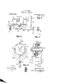
- Fig. l is an elevation from the left of Fig. 3, on a larger scale.
- Fig. 5- is a detail View, partly in section, from the right of Fig. 3, on a larger scale than either of Figs. 3 and 4.
- Fig. 6-- is a detail elevation, partly in section, of the parts shown in Fig. 3, and on a larger scale.
- Fig. 7 is a detail plan View of parts of the automatic reverse mechanism.
- Fig. 8 is a detail of the gear train for reciprocating the work table.
- Fig. 9 is a detail side elevation, partly in section of the tool mounting and cross-feed mechanism.
- Fig. 10 is a detail elevation, partly broken out, of portions of the automatic feed mechanism.
- Fig. 11 -represents a section on line 11-11 of Fig. 10.
- Fig. 12 is a detail showing the spring pressed pin for engaging the angular shaped member to hold the pawl either into or out of engagement with the ratchet wheel.
- Suitable base portions 1-1 and 15 are provided for the machine, the portion 15 hav ing ways 16 for the reciprocating table 17 on which the work is supported or held in the usual. manner.
- a motor 18 has its shaft 1 rovided with a driving pulley 19.
- a shaft 20 mounted in bearings 21 carries the work ing tool 22 which may be a ring-shaped grinder, a hood casing inclosing a portion of the tool.
- the shaft 20 has a pulley 2 1, driven by a belt 25 from the motor pulley 19.
- the frame 26 for the bearings 21 is mounted on ways 27 of the base 141 (see Figs.
- a gear 30 which meshes with a gear 31 carried by a counter shaft 32 having a skew gear 83.
- the latter is actuated by a similar gear 341: carried by a shaft 35 to which a crank or wheel 36 is secured, the latter being located behind the table, as
- a pinion 37 meshing with gear 31 is secured to one end of a shaft 38, the other end of which projects through base 15 at the front thereof said shaft being shown as squared at 39 to receive a crank.
- a pulley 40 see Fig. 2 secured to the tool shaft 20, is connected by a belt 41 with a pulley 42 loose on a shaft 43 mounted in suitable bearings in base 14.
- the hub 45 of pulley 42 is formed or provided with clutch teeth 44 to cooperate with similar teeth carried by a clutch block 46 connected to shaft 43 by a spline 47 (see Fig. 6).
- a lever 48 (see Figs. 3 and 4) is pivoted at 49 to the base or frame of the machine and has yoke pins 50 engaging the clutch block 46.
- Such hand operation may be effected by a crank wheel 58 at the outer end of a shaft 59 the inner end of which has a skew gear 60 meshing with a skew gear 61 secured to shaft 57 (see Figs. and 6).
- the clutch is engaged by a yoke 62 carried by a block 63 secured to a slide bar 64, the latter being operated by a lever 65 pivoted at 66 and having a handle 67 whereby the clutch may be manually shifted.
- a link 68 bears at one end against the block 63, a plunger 69 actuated by a spring 70 in a housing 71 bearing on the other end of said link.
- the lever 65 is connected to a slide or link 72 having a pin 73 (see Figs. 6 and 7).
- An elbow lever 74 has a slot engaging said pin and is connected by a link 75 with a stud 76 projecting rearwardly from a lever 77 pivoted at 78 to the front of the table support or base 15 (see Fig. 1) and having a handle 79 by means of which itmay be manually operated from the front of the machine to shift the clutch 53 to reverse the direction of travel of the work table.
- This lever 77 is automatically operated by either one of two dogs or blocks 80 carried by the table as shown in Fig. 1.
- the under side of the work table is provided with a rack 81 engaged by a gear 82 at one end of a train such as shown in Fig. 8, the gear 83 at the other end of the train being carried by a hub 84 splined on shaft 57 (see Fig. 7).
- Said hub is provided with clutch teeth 86, 37 at its ends, and with an annular groove 88 engaged by a yoke carried by an elbow lever 89 which is connected by a link 90 with a hand lever 91 pivoted at 92 to the front of base 15.
- the hub 84 can be shifted so that its teeth 86 will engage, or be dis engaged from, similar teeth of a collar 93 secured to shaft 57.
- a sleeve or hollow shaft 94 is mounted on the front end of the shaft 57, said sleeve having a hand wheel 95 at one end and clutch teeth 96 at its other end, so that,
- the hub 84 if the hub 84 be shifted to the extreme right in Fig. 7, it can be operated by the hand wheel
- the hand wheel 58 hereinbefore described, is provided.
- the lever 91 at the front of the machine may be used to stop and start the table, the lever 48 at the rear of the table performs practically the same function although it does so through the medium of a different clutch from the one that is shifted by said lever 91.
- the tool 22 may be fed up to the work, in a direction transverse of the path of movement of the work, by hand, either from the front or rear of the table, operation from the latter position being effected through the medium of shaft 35.
- this shaft may be automatically actuated intermittently so as to advance the tool toward the work at the end of each travel of the latter, I provide the mechanism best shown in Figs.
- a disk 97 On the rear end of shaft 57, which is running continuously when the machine is to operate automatically, is secured a disk 97.
- a disk 98 having a crank pin 99 is held against the face of disk 97 by a ringshaped disk 98 as by bolts con necting the two beyond the periphery of the disk 97.
- Disks or plates of suitable friction material 100 are interposed between the disk 97 and the disks 98, 98
- the crank pin 99 is connected by a link 101, with a vertically reciprocating slide 102 mounted in bearings 103 see Fig. 4c, and having a cross head 1041 at its upper end.
- a ratchet wheel 105 Keyed on shaft 35 is a ratchet wheel 105 having double-faced teeth.
- each disk 106 is connected by a link 108 to the cross-head 104:, but the points of connection of the two links with the two disks are diametrically opposite each other, and the pawls are inclined, so that on each stroke of slide 102 up or down, the disks are oscillated in opposite directions, one pawl actuating the ratchet and the other riding idly over it.
- the shaft 57 is rotated continuously when the machine is being run automatically, and consequently the disk 97 must rotate continuously.
- crank disk 98 It becomes essential of course to prevent continued rotation of the shaft disk 98, and permit this to be done only at the end of each longi tudinal movement of the work table.
- To effect the stoppage of rotation of the crank disk 98, 1 provide the back of the disk 98 with two ribs 109 either one of which may cooperate with a fixed stop pin 110 project ing from a fixed part of the machine. Therefore, whenever the table starts on a return movement, the crank disk is rotated until one of the ribs 109 contacts with the stop pin 110 after which the disk 97 slips during the continued movement of the table and rotation of shaft 57.
- the partial rotation of the crank disk 98 has, through the connections described, rotated the screw shaft 29 and has slightly fed the tool up to the work.
- a machine constructed as described can be entirely controlled by the operator standing in one position behind the work table where he can watch the progress of the work, so as to require no running around the end of the table to watch the results on the face of the work.
- Another advantage is that one operator can run two machines from practically one position, provided the second machine has the mechanism for controlling it located behind the other end of the table from that shown in Fig. 1. That is, it being understood that in the machine illustrated the mechanism for controlling from the rear is located behind the left hand end of the table.
- a machine of the character described comprising a longitudinally movable work table, means for feeding the same, a tool for operating upon work supported by said table, manually operable means at the front of the machine for relatively adjusting the tool and the work, a manually operable device located behind the table for relatively adjusting the tool and the work.
- a machine of the character described comprising a longitudinally movable work table, means for feeding the same, a tool for operating upon work supported by said table, means at the front of the machine for relatively adjusting the tool and the work, a manually operable device located behind the table for relatively adjusting the tool and the work, a second manually operable device located behind the table for effecting adj ustrnent of the table independently of the first-mentioned adjustment.
- a machine of the character described comprising a longitudinally movable work table, a tool for operating on one side face of the work carried by said table, a shaft having connections for reciprocating the table, means for rotating the shaft first in one direction and then in the other, a crank disk frictionally connected with said shaft at the rear of the table, means for advancing the tool toward the work, and connections with said crank disk for advancing the tool at the end of each reciprocation of the work table.
- a machine of the character described comprising a longitudinal movable Work table, a tool for operating on one side face of the work carried by said table, a shaft having connections for reciprocating the table, means for rotating the shaft first in one direction and then in the other, a crank disk frictionally connected with said shaft at the rear of the table, means for advancing the and connections between said pawls and tool toward the work, and connections with crank disk for actuating the pawls. 0 said crank disk for advancing the tool at the In testimony whereof I afiix my signature end of each reciprocation of the Work table, in presence of two witnesseses.
- connections including a screw shaft for EVERETT ⁇ V. WIGHT. advancing the tool, a shaft for driving said WVitnesses:
Description
E. W. WIGHT.
METAL WORKING MAGHINE.
APPLIGATION TILED SEPT. 1. 1910.
Patented Nov. 28, 1911.
4 SHEETS-11331 1.
WITNESSES.- figvdbuli- Everett 1% Wight A TTORNEY E. W. WIGHT. METAL WORKING MACHINE.
APPLICATION FILED SEPT. 1. 1910.
1,009,948. Patented Nov. 28, 1911 4 sums-SHEET 2. ma Flg. 3 98\ l m R WITNESSES Everett W. Wight Wag-Mk8 1 www & Q, W Q rron/(5r WITNESSES:
womi r a 9 (275?;
B. W. WIGHT. METAL WORKING MACHINE.
APPLICATION FILED SEPT. II 1910.
Patented Nov. 28, 1911.
4 SHEETS-SHEET 3.
Fig.7 I W Fig. 8
Everettkifight E. W. WIGHT. METAL WORKING MAOHINE.
APPLICATION FILED SEPT.1, 1910.
mi km Patented Nov. 28, 1911.
Fig. 9
INVENTOR Evg reit h. hiykt ATTORNEY UNITED sTAr s rnainntr orinon.
EVERETT W. WIGHT, OF PROVIDENCE, RHODE ISLAND, ASSIGNOB. TO DIAMOND MACHINE COMPANY, OF PROVIDENCE, RHODE ISLAND, A CORPORATION OF RHODE ISLAND.
METAL-WORKING MACHINE.
To all whom it may concern:
Be it known that I, EVERETT W. VVIeIrr, a citizen of the United States, residing at the city of Providence, in the county of Providence and State of Rhode Island, have invented certain new and useful Improve ments in Metal-Working Machines, of which the following is a specification, reference being had therein to the accompanying drawing.
This invention relates to metal working machines, especially of that type having a long reciprocating table for carrying the work back and forth past the tool, the latter being advanced at intervals toward one side of the work, usually at the end of each movement of the table. When the attendant has to control the operations of the machine from a point at the side of the table opposite the location of the tool, he must frequently go around one end of the table to inspect the face of the work being operated upon. For purposes of brevity of description, this side of the table is herein referred to as the front. To get to the back of the table, to watch the progress of the work being done or inspect that which has been done, the attendant must go quite a distance around one end of the table, which is frequently quite long, and often he must first stop the machine to allow time for the inspection.
The object of this invention is to provide a machine of this character with means whereby it may be fully controlled by an attendant at the rear of the table, from which point he can watch the progress of the work. Preferably the machine is also provided with means whereby the movements can be controlled from the front when desired.
To these ends, the invention consists in the construction and combination of parts substantially as hereinafter described and claimed.
In the accompanying drawings, the machine illustrated is of a form well adapted for grinding the side face of a piece of work carried by the table, and wherein the grinding tool is rotated by a shaft mounted horizontally at a right angle to the line of travel of the table; but I do not limit myself to a grinder as the working tool, nor to the angle Specification of Letters Patent.
Application filed September 1, 1910.
Patented Nov. 28, 1911.
Serial No. 580,110.
at which the tool shaft is mounted relatively. to the table.
Of said drawings: Figure 1is a front elevation of the machine. Fig. 2is an end View, from the left of Fig. 1, on a larger scale, and partly in section. Fig. 3-is a plan View of a portion of the mechanism shown in Fig. 2. Fig. lis an elevation from the left of Fig. 3, on a larger scale. Fig. 5-is a detail View, partly in section, from the right of Fig. 3, on a larger scale than either of Figs. 3 and 4. Fig. 6--is a detail elevation, partly in section, of the parts shown in Fig. 3, and on a larger scale. Fig. 7is a detail plan View of parts of the automatic reverse mechanism. Fig. 8is a detail of the gear train for reciprocating the work table. Fig. 9is a detail side elevation, partly in section of the tool mounting and cross-feed mechanism. Fig. 10is a detail elevation, partly broken out, of portions of the automatic feed mechanism. Fig. 11-represents a section on line 11-11 of Fig. 10. Fig. 12is a detail showing the spring pressed pin for engaging the angular shaped member to hold the pawl either into or out of engagement with the ratchet wheel.
Similar reference characters indicate the same or similar parts in all of the views.
Suitable base portions 1-1 and 15 are provided for the machine, the portion 15 hav ing ways 16 for the reciprocating table 17 on which the work is supported or held in the usual. manner. A motor 18 has its shaft 1 rovided with a driving pulley 19. A shaft 20 mounted in bearings 21 carries the work ing tool 22 which may be a ring-shaped grinder, a hood casing inclosing a portion of the tool. The shaft 20 has a pulley 2 1, driven by a belt 25 from the motor pulley 19. The frame 26 for the bearings 21 is mounted on ways 27 of the base 141 (see Figs. 2 and 9) and has a nut 28 engaging a screw shaft 29 by means of which the tool is given its cross feed, or movement to and from the work on the table. Secured to said screw shaft is a gear 30 which meshes with a gear 31 carried by a counter shaft 32 having a skew gear 83. The latter is actuated by a similar gear 341: carried by a shaft 35 to which a crank or wheel 36 is secured, the latter being located behind the table, as
shown in Fig. 2, it being understood that by the front of the table is meant that portion at the extreme right of said figure. This enables the tool to be fed up to the work by hand, while the attendant stands where he can see the rear face of the piece of work. To enable this same cross feed to be controlled from the front of the table, a pinion 37 meshing with gear 31 is secured to one end of a shaft 38, the other end of which projects through base 15 at the front thereof said shaft being shown as squared at 39 to receive a crank.
A pulley 40 see Fig. 2 secured to the tool shaft 20, is connected by a belt 41 with a pulley 42 loose on a shaft 43 mounted in suitable bearings in base 14. The hub 45 of pulley 42 is formed or provided with clutch teeth 44 to cooperate with similar teeth carried by a clutch block 46 connected to shaft 43 by a spline 47 (see Fig. 6). A lever 48 (see Figs. 3 and 4) is pivoted at 49 to the base or frame of the machine and has yoke pins 50 engaging the clutch block 46.
Loosely mounted on the shaft 43 .are two pinions 51-52 (see Fig. 6) and between them a clutch 53 is splined on said shaft. Meshing with pinion 51 isagear 54. A gear 55 meshes with an idler 56 (see Fig. 5) which, in turn, meshes with pinion 52. The gears 54, 55 are secured to a counter-shaft 57. hen shaft 43 is running, the counter shaft 57 will be driven in one direction or the other according to whether the clutch 53 is shifted to engage pinion 51 or pinion 52, and if the clutch is in the intermediate position shown in Fig. 6, the shaft 57 possesses no power-driving connections and may be rotated by hand. Such hand operation may be effected by a crank wheel 58 at the outer end of a shaft 59 the inner end of which has a skew gear 60 meshing with a skew gear 61 secured to shaft 57 (see Figs. and 6). The clutch is engaged by a yoke 62 carried by a block 63 secured to a slide bar 64, the latter being operated by a lever 65 pivoted at 66 and having a handle 67 whereby the clutch may be manually shifted. To cause the clutch to quickly take its new position after passing the intermediate position, a link 68 bears at one end against the block 63, a plunger 69 actuated by a spring 70 in a housing 71 bearing on the other end of said link.
To effect the automatic shifting of the clutch 53 at the end of each direction of travel of the work table, to cause the table to return through the connections hereinafter described, the lever 65 is connected to a slide or link 72 having a pin 73 (see Figs. 6 and 7). An elbow lever 74 has a slot engaging said pin and is connected by a link 75 with a stud 76 projecting rearwardly from a lever 77 pivoted at 78 to the front of the table support or base 15 (see Fig. 1) and having a handle 79 by means of which itmay be manually operated from the front of the machine to shift the clutch 53 to reverse the direction of travel of the work table. This lever 77 is automatically operated by either one of two dogs or blocks 80 carried by the table as shown in Fig. 1.
The under side of the work table is provided with a rack 81 engaged by a gear 82 at one end of a train such as shown in Fig. 8, the gear 83 at the other end of the train being carried by a hub 84 splined on shaft 57 (see Fig. 7). Said hub is provided with clutch teeth 86, 37 at its ends, and with an annular groove 88 engaged by a yoke carried by an elbow lever 89 which is connected by a link 90 with a hand lever 91 pivoted at 92 to the front of base 15. By means of said hand lever, the hub 84 can be shifted so that its teeth 86 will engage, or be dis engaged from, similar teeth of a collar 93 secured to shaft 57. When engaged, and when the parts shown in Fig. 6 are in relative positions to drive shaft 57 the table will be moved along by the train of gearing just described. 1V hen the teeth 86 are disengaged, the table may remain stationary while the rest of the machine is running. In order that the table may be manually operated from the front of the machine, a sleeve or hollow shaft 94 is mounted on the front end of the shaft 57, said sleeve having a hand wheel 95 at one end and clutch teeth 96 at its other end, so that,
if the hub 84 be shifted to the extreme right in Fig. 7, it can be operated by the hand wheel In order that the table may be similarly operated from the rear of the table, the hand wheel 58 hereinbefore described, is provided. And while the lever 91 at the front of the machine may be used to stop and start the table, the lever 48 at the rear of the table performs practically the same function although it does so through the medium of a different clutch from the one that is shifted by said lever 91.
As has been described, the tool 22 may be fed up to the work, in a direction transverse of the path of movement of the work, by hand, either from the front or rear of the table, operation from the latter position being effected through the medium of shaft 35. In order that this shaft may be automatically actuated intermittently so as to advance the tool toward the work at the end of each travel of the latter, I provide the mechanism best shown in Figs.
.10 and 11 in connection with Figs. 2. 4
and 6. On the rear end of shaft 57, which is running continuously when the machine is to operate automatically, is secured a disk 97. A disk 98 having a crank pin 99 is held against the face of disk 97 by a ringshaped disk 98 as by bolts con necting the two beyond the periphery of the disk 97. Disks or plates of suitable friction material 100 are interposed between the disk 97 and the disks 98, 98 The crank pin 99 is connected by a link 101, with a vertically reciprocating slide 102 mounted in bearings 103 see Fig. 4c, and having a cross head 1041 at its upper end. Keyed on shaft 35 is a ratchet wheel 105 having double-faced teeth. Loosely mounted on said shaft, on opposite faces of the ratchet wheel, are two disks 106, each carrying a spring actuated pawl 107. Each disk 106 is connected by a link 108 to the cross-head 104:, but the points of connection of the two links with the two disks are diametrically opposite each other, and the pawls are inclined, so that on each stroke of slide 102 up or down, the disks are oscillated in opposite directions, one pawl actuating the ratchet and the other riding idly over it. As has been mentioned, the shaft 57 is rotated continuously when the machine is being run automatically, and consequently the disk 97 must rotate continuously. It becomes essential of course to prevent continued rotation of the shaft disk 98, and permit this to be done only at the end of each longi tudinal movement of the work table. To effect the stoppage of rotation of the crank disk 98, 1 provide the back of the disk 98 with two ribs 109 either one of which may cooperate with a fixed stop pin 110 project ing from a fixed part of the machine. Therefore, whenever the table starts on a return movement, the crank disk is rotated until one of the ribs 109 contacts with the stop pin 110 after which the disk 97 slips during the continued movement of the table and rotation of shaft 57. The partial rotation of the crank disk 98 has, through the connections described, rotated the screw shaft 29 and has slightly fed the tool up to the work. The slipping of the disks con tinues to the end of the movement of the work table, but when the reverse movement begins, the disk 97 rotates in the other direction and of course the friction disks 100 cause the disk 98 to rotate in the opposite direction until the other rib 109 contacts with the stop pin, the resulting partial rotation of disk 98 actuating the other pawl 107 so as to give another advance movement of the tool toward the work.
It will now be understood that a machine constructed as described can be entirely controlled by the operator standing in one position behind the work table where he can watch the progress of the work, so as to require no running around the end of the table to watch the results on the face of the work. Another advantage is that one operator can run two machines from practically one position, provided the second machine has the mechanism for controlling it located behind the other end of the table from that shown in Fig. 1. That is, it being understood that in the machine illustrated the mechanism for controlling from the rear is located behind the left hand end of the table. With a second machine having its mechanism for controlling from the rear located behind the right hand end of the table, and with such other or second machine turned around so that the two machines are placed back to back, then the attendant simply stands in the space between two tables and can watch the work being done by both machines, and control both of them.
I claim:
1. A machine of the character described comprising a longitudinally movable work table, means for feeding the same, a tool for operating upon work supported by said table, manually operable means at the front of the machine for relatively adjusting the tool and the work, a manually operable device located behind the table for relatively adjusting the tool and the work.
A machine of the character described comprising a longitudinally movable work table, means for feeding the same, a tool for operating upon work supported by said table, means at the front of the machine for relatively adjusting the tool and the work, a manually operable device located behind the table for relatively adjusting the tool and the work, a second manually operable device located behind the table for effecting adj ustrnent of the table independently of the first-mentioned adjustment.
3. A machine of the character described comprising a longitudinally movable work table, a tool for operating on one side face of the work carried by said table, a shaft having connections for reciprocating the table, means for rotating the shaft first in one direction and then in the other, a crank disk frictionally connected with said shaft at the rear of the table, means for advancing the tool toward the work, and connections with said crank disk for advancing the tool at the end of each reciprocation of the work table.
1. A machine of the character described comprising a longitudinal movable Work table, a tool for operating on one side face of the work carried by said table, a shaft having connections for reciprocating the table, means for rotating the shaft first in one direction and then in the other, a crank disk frictionally connected with said shaft at the rear of the table, means for advancing the and connections between said pawls and tool toward the work, and connections with crank disk for actuating the pawls. 0 said crank disk for advancing the tool at the In testimony whereof I afiix my signature end of each reciprocation of the Work table, in presence of two Witnesses.
said connections including a screw shaft for EVERETT \V. WIGHT. advancing the tool, a shaft for driving said WVitnesses:
screw shaft and having a ratchet, a pair of E. C. ATKINS,
paWls for alternately operating said ratchet, SAMUEL RAYNOR.
Copies of this patent may be obtained for five cents each, by addressing the Commissioner of Patents, Washington, D. C.
Priority Applications (1)
| Application Number | Priority Date | Filing Date | Title |
|---|---|---|---|
| US58011010A US1009948A (en) | 1910-09-01 | 1910-09-01 | Metal-working machine. |
Applications Claiming Priority (1)
| Application Number | Priority Date | Filing Date | Title |
|---|---|---|---|
| US58011010A US1009948A (en) | 1910-09-01 | 1910-09-01 | Metal-working machine. |
Publications (1)
| Publication Number | Publication Date |
|---|---|
| US1009948A true US1009948A (en) | 1911-11-28 |
Family
ID=3078258
Family Applications (1)
| Application Number | Title | Priority Date | Filing Date |
|---|---|---|---|
| US58011010A Expired - Lifetime US1009948A (en) | 1910-09-01 | 1910-09-01 | Metal-working machine. |
Country Status (1)
| Country | Link |
|---|---|
| US (1) | US1009948A (en) |
-
1910
- 1910-09-01 US US58011010A patent/US1009948A/en not_active Expired - Lifetime
Similar Documents
| Publication | Publication Date | Title |
|---|---|---|
| US1009948A (en) | Metal-working machine. | |
| US1178400A (en) | Polishing-machine. | |
| US1976103A (en) | Milling machinery | |
| US1376714A (en) | Carriage feed and stop mechanism | |
| US421803A (en) | wurster | |
| US554797A (en) | Machine for grinding handles of table-knives | |
| US2354266A (en) | Machine tool rapid traverse mechanism | |
| US349000A (en) | William f | |
| US821932A (en) | Metal-planning machine. | |
| US1158745A (en) | Automatic lathe. | |
| US1275404A (en) | Portable shaper. | |
| US1581838A (en) | Portable drill and valve grinder | |
| US800667A (en) | Planer. | |
| US453653A (en) | Combined portable planer and key-seating machine | |
| US1114151A (en) | Nut-facing machine. | |
| US1006550A (en) | Grinding-machine. | |
| US392164A (en) | Half to egbert | |
| US570954A (en) | Automatic feed-stop for m etal-plan ing machines | |
| US1412864A (en) | Metal-working machine | |
| US1138289A (en) | Surface-grinding machine. | |
| US1478334A (en) | Profiling machine | |
| US1099617A (en) | Portable rubbing-machine. | |
| US1633060A (en) | Grinding machine | |
| US647332A (en) | Lathe attachment. | |
| US554814A (en) | Office |