US10095177B2 - Cleaner including a transport member configured to transport developer - Google Patents
Cleaner including a transport member configured to transport developer Download PDFInfo
- Publication number
- US10095177B2 US10095177B2 US15/446,151 US201715446151A US10095177B2 US 10095177 B2 US10095177 B2 US 10095177B2 US 201715446151 A US201715446151 A US 201715446151A US 10095177 B2 US10095177 B2 US 10095177B2
- Authority
- US
- United States
- Prior art keywords
- developer
- transport
- cleaning blade
- arm
- shaft
- Prior art date
- Legal status (The legal status is an assumption and is not a legal conclusion. Google has not performed a legal analysis and makes no representation as to the accuracy of the status listed.)
- Active
Links
Images


Classifications
-
- G—PHYSICS
- G03—PHOTOGRAPHY; CINEMATOGRAPHY; ANALOGOUS TECHNIQUES USING WAVES OTHER THAN OPTICAL WAVES; ELECTROGRAPHY; HOLOGRAPHY
- G03G—ELECTROGRAPHY; ELECTROPHOTOGRAPHY; MAGNETOGRAPHY
- G03G21/00—Arrangements not provided for by groups G03G13/00 - G03G19/00, e.g. cleaning, elimination of residual charge
- G03G21/0005—Arrangements not provided for by groups G03G13/00 - G03G19/00, e.g. cleaning, elimination of residual charge for removing solid developer or debris from the electrographic recording medium
- G03G21/0011—Arrangements not provided for by groups G03G13/00 - G03G19/00, e.g. cleaning, elimination of residual charge for removing solid developer or debris from the electrographic recording medium using a blade; Details of cleaning blades, e.g. blade shape, layer forming
- G03G21/0029—Details relating to the blade support
-
- G—PHYSICS
- G03—PHOTOGRAPHY; CINEMATOGRAPHY; ANALOGOUS TECHNIQUES USING WAVES OTHER THAN OPTICAL WAVES; ELECTROGRAPHY; HOLOGRAPHY
- G03G—ELECTROGRAPHY; ELECTROPHOTOGRAPHY; MAGNETOGRAPHY
- G03G21/00—Arrangements not provided for by groups G03G13/00 - G03G19/00, e.g. cleaning, elimination of residual charge
- G03G21/10—Collecting or recycling waste developer
- G03G21/105—Arrangements for conveying toner waste
-
- G—PHYSICS
- G03—PHOTOGRAPHY; CINEMATOGRAPHY; ANALOGOUS TECHNIQUES USING WAVES OTHER THAN OPTICAL WAVES; ELECTROGRAPHY; HOLOGRAPHY
- G03G—ELECTROGRAPHY; ELECTROPHOTOGRAPHY; MAGNETOGRAPHY
- G03G21/00—Arrangements not provided for by groups G03G13/00 - G03G19/00, e.g. cleaning, elimination of residual charge
- G03G21/10—Collecting or recycling waste developer
- G03G21/12—Toner waste containers
Definitions
- the present invention relates to a cleaning unit and an image forming apparatus.
- a cleaning unit includes a cleaning member, an accommodating portion, and a transport member.
- the cleaning member removes a developer from a surface of an image carrier.
- the accommodating portion accommodates the removed developer.
- the transport member transports the developer removed by the cleaning member to the accommodating portion.
- the transport member includes a shaft member, a first transport body, and a second transport body.
- the shaft member extends in a direction intersecting a transport direction of the developer.
- the first transport body is rotatably supported by the shaft member.
- the second transport body is rotatably supported by the first transport body at a position spaced from the shaft member.
- the second transport body extends toward the cleaning member.
- FIG. 1 is an overall explanatory view of an image forming apparatus of Example 1;
- FIG. 2 is an enlarged view of a main part of a photoconductor cleaner of Example 1;
- FIG. 3 is a perspective view of a main part of the photoconductor cleaner of Example 1;
- FIG. 4 is an explanatory view of a rotational trajectory of each part in a transport member of Example 1;
- FIG. 5 is an explanatory view of an inclination angle of a horizontal frame portion of Example 1;
- FIGS. 6A to 6D are explanatory views of an operation of the transport member of Example 1, in which FIG. 6A is an explanatory view illustrating the same state as FIG. 2 , FIG. 6B is an explanatory view illustrating a state in which the transport member is rotated by about 30° about a rotation axis from the state of FIG. 6A , FIG. 6C is an explanatory view illustrating a state in which the transport member is rotated by about 30° about the rotation axis from the state of FIG. 6B , and FIG. 6D is an explanatory view illustrating a state in which the transport member is rotated by about 30° about the rotation axis from the state of FIG. 6C ;
- FIGS. 7A to 7D are explanatory views of an operation of the transport member of Example 1, in which FIG. 7A is an explanatory view illustrating a state in which the transport member is rotated by about 30° about the rotation axis from the state of FIG. 6D , FIG. 7B is an explanatory view illustrating a state in which the transport member is rotated by about 30° about the rotation axis from the state of FIG. 7A , FIG. 7C is an explanatory view illustrating a state in which the transport member is rotated by about 30° about the rotation axis from the state of FIG. 7B , and FIG. 7D is an explanatory view illustrating a state in which the transport member is rotated by about 30° about the rotation axis from the state of FIG. 7C ; and
- FIGS. 8A to 8D are explanatory views of an operation of the transport member of Example 1, in which FIG. 8A is an explanatory view illustrating a state in which the transport member is rotated by about 30° about the rotation axis from the state of FIG. 7D , FIG. 8B is an explanatory view illustrating a state in which the transport member is rotated by about 30° about the rotation axis from the state of FIG. 8A , FIG. 8C is an explanatory view illustrating a state in which the transport member is rotated by about 30° about the rotation axis from the state of FIG. 8B , and FIG. 8D is an explanatory view illustrating a state in which the transport member is rotated by about 30° about the rotation axis from the state of FIG. 8C .
- a front and rear direction will be referred to as an X-axis direction
- a right and left direction will be referred to as a Y-axis direction
- an up and down direction will be referred to as a Z-axis direction
- directions or sides indicated by arrows X, ⁇ X, Y, ⁇ Y, Z, and ⁇ Z will be referred to as forward, rearward, rightward, leftward, upward, and downward, or a front side, a rear side, a right side, a left side, an upper side, and a lower side, respectively.
- FIG. 1 is an overall explanatory view of an image forming apparatus of Example 1.
- a front cover U 1 a as an example of an opening and closing member is supported on a front surface of a printer main body U 1 as an example of an image forming apparatus main body.
- the front cover U 1 a is supported to be openable about a lower end.
- the front cover U 1 a is capable of opening the front side of the printer main body U 1 .
- An exit tray TRh as an example of a discharge unit is formed on an upper surface of the printer U.
- a rear cover U 1 b as an example of an opening and closing member is rotatably supported at the rear side of the printer main body U 1 .
- the rear cover U 1 b is supported to be rotatable between a closed position indicated by a solid line and an opened position indicated by a broken line.
- the rear cover U 1 b as an example of an opening and closing member is capable of opening the rear side of the printer main body U 1 in a case where a paper jam occurs or in a case where an interior inspection and the like are performed.
- the printer U of Example 1 has a controller C as an example of a controller.
- An image processing system IPS, a laser driving circuit DL as an example of a latent image forming circuit, and a power source circuit E are electrically connected to the controller C. Therefore, the controller C is capable of outputting a control signal to the image processing system IPS and the like.
- a photoconductor PR as an example of a rotationally driven image carrier is supported at a rear side of the printer U.
- a charging roller CR, a latent image forming device LH, a developing device G, a transfer roller Tr as an example of a transfer member, and a photoconductor cleaner CL as an example of a cleaning unit for the image carrier are disposed along a rotation direction of the photoconductor PR around the photoconductor PR as an example of a rotating member.
- a charging roller cleaner CRc as an example of a cleaning unit for a charging unit is disposed to face and be in contact with the charging roller CR.
- the latent image forming device LH of Example 1 is configured as a so-called LED head, i.e. a device in which light emitting diodes (LEDs) as an example of a latent image writing element are linearly disposed to be spaced from each other along the right and left direction.
- LED head i.e. a device in which light emitting diodes (LEDs) as an example of a latent image writing element are linearly disposed to be spaced from each other along the right and left direction.
- the developing device G has a developing container V in which a developer is accommodated.
- a developing roller Ga as an example of a developer carrier is disposed to face the photoconductor PR.
- a pair of circulation transport members Gb and Gc and a supply member Gd are disposed within the developing container V in the order of being away from the developing roller Ga.
- a layer thickness regulating member Ge is disposed to face the developing roller Ga.
- a developer replenishing port V 1 as an example of a replenishing unit is formed in the front-side upper surface of the developing container V.
- a developer replenishing path V 3 as an example of a developer transport path is connected to the developer replenishing port V 1 .
- the developer replenishing path V 3 is formed in a cylindrical shape extending forward.
- a replenishing auger V 4 as an example of a developer transport member is rotatably supported in the developer replenishing path V 3 .
- a cartridge holder KH as an example of an attaching and detaching unit is connected to the front end of the developer replenishing path V 3 .
- a toner cartridge TC as an example of an accommodating container for the developer is detachably supported by the cartridge holder KH.
- An inlet port (not illustrated) is formed in the cartridge holder KH and configured such that the developer is capable of flowing into the inlet port from the toner cartridge TC.
- a sheet feeding tray TR 1 as an example of an accommodating unit that accommodates the medium is disposed at a lower side of the printer U.
- a pickup roller Rp as an example of a medium ejecting member is disposed at the rear side of the sheet feeding tray TR 1 .
- Handling rollers Rs as an example of a medium handling member, are disposed at a rear side of the pickup roller Rp.
- Registration rollers Rr as an example of a timing adjusting member are disposed at an upper side of the handling rollers Rs.
- a fixing device F is disposed at an upper side of a transfer region Q 4 in which the photoconductor PR and the transfer roller Tr face each other.
- the fixing device F includes a pair of fixing rollers Fh and Fp as an example of a fixing member, and a fixing region Q 6 is formed by a press contact region of the pair of fixing rollers Fh and Fp.
- Sheet guides SG 1 and SG 2 as an example of a guide member for the medium are disposed at an upper side of the fixing device F.
- Discharge rollers R 1 as an example of a discharge member are disposed at a front side of the sheet guides SG 1 and SG 2 .
- Print information is transmitted to the controller C of the printer U from a host computer and the like as an example of an external information transmitting device.
- the controller C receives the print information, an image forming operation is started.
- the controller C outputs the print information to the image processing system IPS.
- the image processing system IPS converts the print information into image information for forming a latent image, and outputs the image information to a laser driving circuit DL as an example of an image writing circuit at a preset time, that is, at a preset timing.
- the laser driving circuit DL outputs a driving signal to the latent image forming device LH.
- the photoconductor PR When the image forming operation is started, the photoconductor PR begins to rotate.
- a charging voltage is applied to the charging roller CR from the power source circuit E.
- the charging roller CR charges the surface of the photoconductor PR.
- the charging roller cleaner CRc cleans the surface of the charging roller CR.
- the latent image forming device LH forms an electrostatic latent image, which corresponds to the image information, on the surface of the photoconductor PR.
- the pair of circulation transport members Gb and Gc circulate and transport the developer in the developing container V while agitating the developer.
- the supply member Gd transports the developer agitated by the circulation transport members Gb and Gc to the developing roller Ga.
- a layer thickness of the developer on a surface of the developing roller Ga is regulated when the developer passes through a region that faces the layer thickness regulating member Ge.
- a developing voltage is applied to the developing roller Ga from the power source circuit E.
- the electrostatic latent image of the photoconductor PR is developed as a visible image by the developer of the developing roller Ga.
- the replenishing auger V 4 is driven, and the developing device G is replenished with the developer from the toner cartridge TC.
- the pickup roller Rp sends the recording sheet S accommodated in the sheet feeding tray TR 1 .
- the handling rollers Rs separate the recording sheets S one by one.
- the recording sheets S, which are separated by the handling rollers Rs one by one, are sent to the registration rollers Rr.
- the registration roller Rr transports the recording sheet S to the transfer region Q 4 at a predetermined timing.
- a transfer voltage is applied to the transfer roller Tr from the power source circuit E.
- the transfer roller Tr transfers a toner image on the photoconductor PR to the recording sheet S that passes through the transfer region Q 4 .
- the photoconductor cleaner CL removes residual toner on the surface of the photoconductor PR.
- the fixing region Q 6 is formed by the press contact region of the fixing rollers Fh and Fp.
- the toner image is fixed on the recording sheet S transported to the fixing device F by the pair of fixing rollers Fh and Fp in the fixing region Q 6 .
- the recording sheet S, on which the toner image is fixed, is guided by the sheet guides SG 1 and SG 2 .
- the discharge rollers R 1 discharge the recording sheet S to the exit tray TRh.
- FIG. 2 is an enlarged view of a main part of the photoconductor cleaner of Example 1.
- FIG. 3 is a perspective view of a main part of the photoconductor cleaner of Example 1.
- the photoconductor cleaner CL of Example 1 includes a cleaner container 1 as an example of a cleaning container.
- the cleaner container 1 includes a container main body 2 at the lower side thereof, and a cover 3 as an example of a lid member at the upper side thereof.
- the container main body 2 is formed in a box shape and disposed at the front side of the charging roller CR.
- An accommodating portion 2 a is formed in the container main body 2 .
- An inclined surface 2 b which is inclined upward toward the rear side, is formed at the rear side of the accommodating portion 2 a .
- first lower guide portions 6 are formed at positions corresponding to an upper side of the inclined surface 2 b .
- the upper surfaces of the first lower guide portions 6 are inclined downward toward the rear side.
- a second lower guide portion 7 is formed at a rear side of each of the first lower guide portions 6 .
- the upper surface of the second lower guide portion 7 is inclined downward toward the rear side.
- an inclination angle, with respect to a horizontal direction, of the upper surfaces of the second lower guide portions 7 is greater than that of the upper surfaces of the first lower guide portions 6 along the transport direction Ya of the recovered developer.
- a first upper guide portion 11 is formed at the position corresponding to each first lower guide portion 6 .
- a lower surface of the first upper guide portion 11 is formed to be parallel with the upper surface of the first lower guide portion 6 .
- a first guide groove 12 as an example of a first regulating portion is configured with a space between the first lower guide portion 6 and the first upper guide portion 11 .
- the first guide groove 12 of Example 1 is formed approximately along the transport direction Ya of the developer.
- a second upper guide portion 13 are formed at a position facing the second lower guide portion 7 .
- the lower surface of the second upper guide portion 13 is formed to be parallel with the upper surface of the second lower guide portion 7 .
- a second guide groove 14 as an example of a second regulating portion is configured with a space between the second lower guide portion 7 and the second upper guide portion 13 .
- the second guide groove 14 of Example 1 is formed along the transport direction of the developer.
- a blade holder 21 as an example of a support body for a cleaning member is supported on an external surface at an upper side of the rear end of the container main body 2 .
- the blade holder 21 of Example 1 is supported on the container main body 2 via a seal 22 as an example of a sealing member.
- the blade holder 21 of Example 1 is formed by bending a metal plate in an L shape.
- the blade holder 21 has a supported portion 21 a supported on the seal 22 , and a holder main body 21 b extending from the upper end of the supported portion 21 a toward the cleaning region Q 5 .
- a cleaning blade 23 as an example of a cleaning member is supported on a lower surface of the rear end of the holder main body 21 b . In the cleaning region Q 5 , a tip end of the cleaning blade 23 is in contact with the photoconductor PR.
- the cleaning blade 23 of Example 1 is configured with a rubber blade as an example of an elastic material.
- Example 1 a space surrounded by the upper surfaces of the holder main body 21 b and the cleaning blade 23 and the cover 3 becomes a transport path through which the developer recovered in the cleaning region Q 5 is transported.
- the transport direction Ya of the developer is a direction that is coincident with the inclination of the upper surface of the cleaning blade 23 .
- the description “along the transport direction of the developer” is not limited only to being exactly parallel with the transport direction of the developer, but is used to mean that its main component is the transport direction of the developer, that is, to mean including directions in the range of ⁇ 45 degrees with respect to the transport direction of the developer without.
- FIG. 4 is an explanatory view of a rotational trajectory of each part in the transport member of Example 1.
- a transport member 31 is disposed at an upper side of the cleaning blade 23 .
- the transport member 31 has an agitation unit 32 as an example of a first transport body at the front side thereof, and a transport unit 33 as an example of a second transport body at the rear side thereof.
- the agitation unit 32 has a configuration of a grid pattern combined with a plate-shaped member that extends in the right and left direction and the front and rear direction.
- a crank shaft S 1 as an example of a shaft member is disposed at a central portion in the front and rear direction of the agitation unit 32 .
- the crank shaft S 1 has a rotation center S 1 a , and a connecting member S 1 b as an example of an eccentric portion that is eccentric from the rotation center S 1 a .
- the connecting member S 1 b is configured with a member that extends in a radial direction of the crank shaft S 1 .
- the agitation unit 32 is rotatably supported at the radial outer end the connecting member S 1 b in the radial direction. Therefore, in Example 1, a connecting portion S 1 c between the agitation unit 32 and the connecting member S 1 b rotates along a crank trajectory T 1 in FIG. 4 as the crank shaft S 1 rotates.
- crank shaft S 1 is formed in a rod shape extending in the right and left direction.
- the left end of the crank shaft S 1 penetrates the cleaner container 1 and extends to the outside, and a driving power is transmitted from a non-illustrated motor as an example of a driving source.
- first guide projections 32 b as an example of a first guided portion are formed as an example of a first regulated portion.
- the first guide projections 32 b are formed to protrude outward from the left and right ends of the agitation unit 32 .
- the first guide projections 32 b are supported in a state of being fitted into the first guide grooves 12 , respectively. Therefore, the first guide projections 32 b are supported to be movable along the first guide grooves 12 , respectively. Accordingly, the first guide projections 32 b move along a first projection trajectory T 2 in FIG. 4 .
- the agitation unit 32 is supported by the crank shaft S 1 and the first guide projections 32 b , and supported in the cleaner container 1 in a posture inclined downward toward the left side.
- a pushing portion 32 c is formed at the front end of the agitation unit 32 . Further, the pushing portion 32 c of Example 1 rotates along a pushing trajectory T 3 in FIG. 4 as the crank shaft S 1 rotates.
- a transport connection portion 32 d as an example of a first support portion is formed at a position more forward than the first guide projection 32 b .
- the agitation unit 32 is supported by the connecting member S 1 b of the crank shaft S 1 and the first guide projection 32 b such that as the crank shaft S 1 rotates, the transport connection portion 32 d rotates along an elliptical trajectory elongated in the transport direction of the developer as indicated by a connection portion trajectory T 4 in FIG. 4 .
- the front end portion of the transport unit 33 is rotatably supported by the transport connection portion 32 d of the agitation unit 32 .
- the transport unit 33 has a downstream portion 34 at the front side thereof, and an upstream portion 36 at the rear side thereof.
- the downstream portion 34 has a pair of left and right frame portions 34 a at the left and right ends thereof. Further, no member is disposed inside the frame portion 34 a of the downstream portion 34 of Example 1.
- a position regulating projection 34 b as an example of a second guide portion is formed at a rear end of the downstream portion 34 an example of a second regulating portion.
- the position regulating projection 34 b is supported to be movable along the second guide groove 14 . Accordingly, the position regulating projection 34 b moves along a second projection trajectory T 5 in FIG. 4 . Further, as illustrated in FIG. 4 , in Example 1, the movable range of the position regulating projection 34 b along the transport direction of the developer is set to a downstream side (front side) across the position of the supported portion 21 a of the blade holder 21 .
- the transport unit 33 of Example 1 is supported in the cleaner container 1 by the transport connection portion 32 d , which is a portion connected to the agitation unit 32 , and the position regulating projection 34 b . Accordingly, as the crank shaft S 1 rotates, a tip end of the upstream portion 36 of the transport unit 33 rotates along an elliptical trajectory elongated along the transport direction of the developer as indicated by a transport trajectory T 6 in FIG. 4 . Further, in Example 1, in a state viewed in a direction represented in FIG.
- the rotation directions of the crank trajectory T 1 , the pushing trajectory T 3 , and the transport trajectory T 6 are set to be rotated in a clockwise direction, and the rotation direction of the connection portion trajectory T 4 is set to be rotated in a counterclockwise direction.
- the movable range of the position regulating projection 34 b is set such that a trajectory of the connection portion 32 d is the trajectory T 4 downstream of a bent portion of the blade holder 21 (a position where a lower surface of a transport path of the developer is bent), that is, such that the connection portion 32 d is not positioned on the holder main body 21 b.
- the upstream portion 36 is formed in a grid pattern having vertical frame portions 37 as an example of a support portion, and horizontal frame portions 38 as an example of a main body of the transport unit.
- the vertical frame portions 37 are formed in a plate shape extending in the front and rear direction
- the horizontal frame portions 38 are formed in a plate shape extending in the right and left direction.
- a lower surface of the upstream portion 36 is disposed to be spaced from the upper surfaces of the holder main body 21 b and the cleaning blade 23 so as not to be in contact with the upper surfaces of the holder main body 21 b and the cleaning blade 23 when the transport member 31 is moved.
- the vertical frame portion 37 is configured such that a width in the up and down direction is increased from the rear side, which is the upstream side, toward the front side which is the downstream side with respect to the transport direction Ya of the developer along the holder main body 21 b .
- plural vertical frame portions 37 are disposed to be spaced from each other in the width direction of the recording sheet S.
- FIG. 5 is an explanatory view of an inclination angle of the horizontal frame portions of Example 1.
- Example 1 includes a first horizontal frame portion 38 a , a second horizontal frame portion 38 b , a third horizontal frame portion 38 c , and a fourth horizontal frame portion 38 d in this order from the upstream side in the transport direction Ya of the developer.
- the front surfaces of the respective horizontal frame portions 38 a to 38 d are inclined in a direction approaching the holder main body 21 b or the cleaning blade 23 toward the upstream side in the transport direction Ya of the developer.
- the inclination angle ⁇ 1 in the transport direction Ya of the developer, of the front surfaces of the first horizontal frame portion 38 a and the second horizontal frame portion 38 b , which are disposed to corresponding to a position of the cleaning blade 23 , is set to be larger than the inclination angle ⁇ 2 of the front surfaces of the third horizontal frame portion 38 c and the fourth horizontal frame portion 38 d , which are disposed to correspond to the holder main body 21 b . That is, the inclination angles are set to be ⁇ 1 > ⁇ 2 .
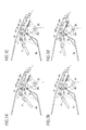
- FIGS. 6A to 6D are explanatory views of an operation of the transport member of Example 1, in which FIG. 6A is an explanatory view illustrating the same state as FIG. 2 , FIG. 6B is an explanatory view illustrating a state in which the transport member is rotated by about 30° about a rotation axis from the state of FIG. 6A , FIG. 6C is an explanatory view illustrating a state in which the transport member is rotated by about 30° about the rotation axis from the state of FIG. 6B , and FIG. 6D is an explanatory view illustrating a state in which the transport member is rotated by about 30° about the rotation axis from the state of FIG. 6C .
- FIGS. 7A to 7D are explanatory views of an operation of the transport member of Example 1, in which FIG. 7A is an explanatory view illustrating a state in which the transport member is rotated by about 30° about the rotation axis from the state of FIG. 6D , FIG. 7B is an explanatory view illustrating a state in which the transport member is rotated by about 30° about the rotation axis from the state of FIG. 7A , FIG. 7C is an explanatory view illustrating a state in which the transport member is rotated by about 30° about the rotation axis from the state of FIG. 7B , and FIG. 7D is an explanatory view illustrating a state in which the transport member is rotated by about 30° about the rotation axis from the state of FIG. 7C .
- FIGS. 8A to 8D are explanatory views of an operation of the transport member of Example 1, in which FIG. 8A is an explanatory view illustrating a state in which the transport member is rotated by about 30° about the rotation axis from the state of FIG. 7D , FIG. 8B is an explanatory view illustrating a state in which the transport member is rotated by about 30° about the rotation axis from the state of FIG. 8A , FIG. 8C is an explanatory view illustrating a state in which the transport member is rotated by about 30° about the rotation axis from the state of FIG. 8B , and FIG. 8D is an explanatory view illustrating a state in which the transport member is rotated by about 30° about the rotation axis from the state of FIG. 8C .
- the transport unit 33 also moves as follows: the first horizontal frame portion 38 a , which is the tip end, moves to the downstream side along the transport direction Ya of the developer as illustrated in FIGS. 6A to 6D , then moves to the upstream side in the opposite direction to the transport direction Ya of the developer while moving upward as illustrated in FIGS. 7A to 7D , and then moves rightward and downward as illustrated in FIGS. 8A to 8D . Therefore, the tip end of the transport unit 33 also reciprocally moves along the transport trajectory T 6 having an approximately elliptical shape elongated along the transport direction.
- JP-A-2005-010751 in the configuration disclosed in JP-A-2011-149981, a tip end portion of a waste toner transport member is configured to greatly shake in the up and down direction in accordance with eccentricity of the rotation axis. Accordingly, is the configuration of Patent Document 2 has the same problem. This is because the transport members disclosed in JP-A-2005-010751 and JP-A-2011-149981 are configured such that a single transport member is directly driven by the crank shaft.
- the transport member 31 is configured such that the agitation unit 32 and the transport unit 33 are connected by the transport connection portion 32 d , and the tip end of the transport unit 33 moves along the transport trajectory T 6 having an approximately elliptical shape elongated in the transport direction. Accordingly, compared with the configurations of JP-A-2005-010751 and JP-A-2011-149981, it is possible to reduce the space at the upper side of the cleaning blade 23 in the cleaner container 1 while securing the transport performance of the transport member 31 . Accordingly, compared with the configurations of JP-A-2005-010751 and JP-A-2011-149981, it is possible to minimize the photoconductor cleaner CL while ensuring the transport performance.
- the photoconductor cleaner CL of Example 1 in a state in which the transport unit 33 is in the states illustrated in FIGS. 6A to 6D , the developer, which is pushed by the front surface of the first horizontal frame portion 38 a and recovered from the photoconductor PR by the cleaning blade 23 , is transported toward the accommodating portion 2 a . Further, in the states illustrated in FIGS. 7A to 7D , the first horizontal frame portion 38 a moves to the upstream side in the transport direction Ya of the developer while being spaced away from the cleaning blade 23 and the holder main body 21 b .
- the developer which is transported to the downstream side in FIGS. 6A to 6D , is less transported in the reverse direction. Further, as illustrated in FIGS. 8A to 8D , the first horizontal frame portion 38 a moves to a position in the vicinity of the cleaning region Q 5 , and returns to the state of FIG. 6A .
- the developer recovered by the cleaning blade 23 is transported to the accommodating portion 2 a by the transport member 31 . Further, the developer transported to the accommodating portion 2 a is pushed into the interior of the accommodating portion 2 a by the pushing portion 32 c that rotates along the pushing trajectory T 3 . In addition, when the developer transported to the accommodating portion 2 a is accumulated, the developer is leveled by being agitated by the agitation unit 32 that reciprocally moves.
- the pushing portion 32 c reciprocally moves along a trajectory having an elliptical shape that is relatively long in the vertical direction as indicated by the pushing trajectory T 3 . Accordingly, it is easy to agitate the developer while pushing the developer downward to be pressed. Accordingly, the recovered developer can be easily pressed, and the recoverable amount of the developer can be increased compared with a case in which the developer is not pressed.
- the horizontal frame portions 38 a to 38 d have surfaces (upper surfaces and lower surfaces) inclined to the upper surface side of the holder main body 21 b and the like toward the upstream side in the transport direction Ya of the developer. Therefore, as illustrated in FIGS. 6A to 6D , when the horizontal frame portions 38 a to 38 d move from the upstream side to the downstream side in the transport direction Ya of the developer, the developer on the upper surface of the holder main body 21 b or the cleaning blade 23 receives a force in a direction in which the developer is pressed against the upper surface of the holder main body 21 b or the like.
- Example 1 a force is applied to push the developer against the upper surfaces of the holder main body 21 b and the like which are the bottom surfaces of the transport path. Therefore, when the transport unit 33 moves in the transport direction Ya of the developer in a state in which the force to push the developer is applied, not only the developer, which is in direct contact with the horizontal frame portions 38 a to 38 d , but also the developer, which is pushed by the developer, which is in direct contact with the horizontal frame portions 38 a to 38 d , to be present between the transport unit 33 and the upper surfaces of the holder main body 21 b and the like, is easily transported in the transport direction Ya of the developer. Therefore, compared with the technique disclosed in JP-A-2005-010751, the transport efficiency (recovery efficiency) of the developer is improved. Accordingly, the stagnation of the developer is reduced, and the transport failure of the developer is also reduced.
- the inclination angle ⁇ 1 of the horizontal frame portions 38 a and 38 b corresponding to the cleaning blade 23 is greater than the inclination angle ⁇ 2 of the horizontal frame portions 38 c and 38 d corresponding to the holder main body 21 b .
- the inclination angle ⁇ 1 is small, the force for pushing the developer against the cleaning blade 23 or the holder main body 21 b becomes strong.
- the cleaning blade 23 made of an elastic material receives an external force, there is a concern that the value of pressure and the distribution of pressure in the width direction in the cleaning region Q 5 are adversely affected. That is, there is a concern that the cleaning efficiency deteriorates so that a cleaning failure occurs.
- Example 1 an adverse influence on the cleaning blade 23 is reduced compared with a case in which the inclination angle ⁇ 1 of the horizontal frame portions 38 a and 38 b corresponding to the cleaning blade 23 is equal to the inclination angle ⁇ 2 of the horizontal frame portions 38 c and 38 d corresponding to the holder main body 21 b . Accordingly, the occurrence of the cleaning failure is reduced.
- Example 1 the transport member 31 is provided with the horizontal frame portions 38 at the upstream portion 36 thereof, but is not provided the horizontal frame portions 38 at the downstream portion 34 thereof. Therefore, the downstream portion 34 is poor compared with the upstream portion 36 in terms of the ability of transporting the developer to the downstream side in the transport direction Ya.
- the transport member 31 of Example 1, a moves in a reverse flow direction in relation to the transport direction Ya when the trajectory of a reciprocal movement transits from the state illustrated in FIG. 7A to the state illustrated in FIG. 8A via the states illustrated in FIGS. 7B, 7C, and 7D .
- a part of the developer may flow reversely when the transport member moves in the reverse flow direction ( ⁇ Ya).
- the situation in which the developer stagnates grows up toward the downstream side in the developer transport direction Ya. Accordingly, there is a concern that the developer aggregates at the downstream side in the transport direction Ya of the developer by a force for transporting the developer from the upstream side and a force for pushing the developer in the reverse flow direction. When the developer aggregates at a position in the middle of the transport member, there is a concern that the developer is blocked so that a transport failure of the developer occurs.
- Example 1 the transport force of the downstream portion 34 is low compared to the upstream portion 36 . Accordingly, the force received by the developer in the reverse flow direction is lower than the force received by the developer in the transport direction Ya. Therefore, in Example 1, the aggregation of the developer is reduced compared with a case in which the transport force at the upstream portion and the transport force at the downstream portion are the same. Accordingly, a transport failure of the developer is reduced.
- Example 1 the transport force of the developer at the downstream portion 34 is zero. Accordingly, the force in the reverse flow direction, which is received by the developer, becomes zero. Therefore, compared with a case in which the downstream portion 34 has the transport force, the aggregation of the developer is further reduced. Further, the developer transported to the range of the downstream portion 34 is pushed by the developer transported from the upstream side at the upstream portion 36 and is transported to the downstream side.
- Example 1 a downstream end of the downstream portion 34 is disposed downstream of the upstream end of the inclined surface 2 b of the container main body 2 .
- the downstream portion 34 is disposed across the upstream end of the inclined surface 2 b of the container main body 2 . Accordingly, the downstream portion 34 in the transport direction Ya is disposed across the upstream end of the inclined surface 2 b.
- Example 1 in the transport member 31 , the agitation unit 32 and the transport unit 33 are rotatably connected.
- the transport member has a flat plate shape as in the configurations disclosed in JP-A-2005-010751 and JP-A-2011-149981, a length along the transport direction is also increased, and thus it is difficult to reduce the overall size of the photoconductor cleaner CL.
- the agitation unit 32 and the transport unit 33 are rotatably connected so that the transport member 31 is supported in a bent state. Therefore, compared with the configurations disclosed in JP-A-2005-010751 and JP-A-2011-149981, it is possible to reduce the overall length of the transport member 31 , and to miniaturize the photoconductor cleaner CL.
Landscapes
- Physics & Mathematics (AREA)
- General Physics & Mathematics (AREA)
- Life Sciences & Earth Sciences (AREA)
- Engineering & Computer Science (AREA)
- Environmental & Geological Engineering (AREA)
- Sustainable Development (AREA)
- Cleaning In Electrography (AREA)
Abstract
Description
- (H01) In the above described example, a printer U is exemplified as an example of an image forming apparatus. Without being limited thereto, however, the image forming apparatus may be, for example, a copier, a FAX, or a multifunction machine having plural or all functions thereof.
- (H02) In the above described example, the printer U is exemplified as having a configuration in which a monochromatic developer is used. Without being limited thereto, however, the present invention may also be applied to, for example, an apparatus for forming a multiple color image having two or more colors.
- (H03) In the above described example, the inclination angles α1 and α2 of the horizontal frame portions 38 may be set to be α1>α2 as exemplified in the example, but the present invention is not limited thereto. For example, the inclination angles α1 and α2 may be set to be α1=α2. In addition, regarding the four
horizontal frame portions 38 a to 38 d, for example, a variation may be made to the configuration in such a manner in which the inclination angle is increased toward the downstream side. Further, the number ofhorizontal frame portions 38 a to 38 d may be three or less, or five or more without being limited to four. Further, the vertical frame portions 37 may be provided for strength, but a configuration may be made in which no vertical frame portion is provided. - (H04) In the above described example, a configuration in which the
downstream portion 34 of thetransport member 31 does not have transport ability is exemplified, but the present invention is not limited thereto. The configuration may be made such thedownstream portion 34 has lower transport ability than that of theupstream portion 36. For example, the horizontal frame portions may be provided in such a manner that the interval of the horizontal frame portions in thedownstream portion 34 is wider than that in theupstream portion 36. Alternatively, the horizontal frame portions may be provided in such a manner that the height of the horizontal frame portions in thedownstream portion 34 is lower than that in theupstream portion 36. - (H05) In the above described example, the downstream end of the
downstream portion 34 may be disposed downstream of the upstream end of theinclined surface 2 b. However, the downstream end of thedownstream portion 34 may be disposed upstream of the upstream end of theinclined surface 2 b. - (H06) In the above described example, the transport ability of the
downstream portion 34 may be lower than the transport ability of theupstream portion 36, but theupstream portion 36 and thedownstream portion 34 may be made to have the same transport ability. - (H07) In the above described example, regarding the
agitation unit 32, a distance between the connecting portion S1 c and the rotation center S1 a, a distance between the connecting portion S1 c and thefirst guide projection 32 b, a distance between thefirst guide projection 32 b and thetransport connection portion 32 d, and a distance between the connecting portion S1 c and the pushingportion 32 c may be arbitrarily changed in accordance with a design and specification. Further, when the distance between thefirst guide projection 32 b and thetransport connection portion 32 d is decreased, the connection portion trajectory T4 becomes a more flat elliptical trajectory than the trajectory described in Example 1. That is, it is possible to further narrow a space at an upper side while securing a distance by which thetransport unit 33 reciprocally moves. In addition, when the distance between the connecting portion S1 c and the pushingportion 32 c is increased, the inner diameter of the pushing trajectory T3 is increased, and as a result, it is possible to strengthen the force for pushing the developer. Further, as the distance between the connecting portion S1 c and the rotation center S1 a is increased, it is possible to further horizontally increase the transport trajectory T6 of thetip end 38 d, and thus to improve the transport performance. - (H08) In the above described example, regarding the
transport unit 33, a distance between thetransport connection portion 32 d and theposition regulating projection 34 b and a distance between theposition regulating projection 34 b and the tip end 38 a may be changed arbitrarily in accordance with a design and specification. Further, when a ratio of the distance between theposition regulating projection 34 b and the tip end 38 a to the distance between thetransport connection portion 32 d and theposition regulating projection 34 b is decreased, the transport trajectory T6 of the tip end 38 a is horizontally elongated, and as a result, it is possible to further narrow a space at the upper side. - (H09) In the above described example, a configuration is exemplified in which the
guide grooves cleaner container 1, and theprojections transport member 31, but the present invention is not limited thereto. For example, it is also possible to form the projection in thecleaner container 1 and to form the groove in thetransport member 31. In addition, at one end side in a sheet width direction, the projection may be formed in thecleaner container 1, and the groove may be formed in thetransport member 31, and at the other end side in the sheet width direction, the groove may be formed in thecleaner container 1, and the projection may be formed on thetransport member 31. - (H010) In the above described example, the pushing
portion 32 c may have any shape as long as the developer can be leveled without being limited to the illustrated shape. Further, although it is desirable to provide the pushingportion 32 c, a configuration may be made in such a manner that no pushing portion is provided. - (H011) In the above described example, the crank shaft S1 is exemplified as an example of a shaft member, but the shaft member may also be configured as a non-eccentric rotating shaft.
Claims (17)
Applications Claiming Priority (2)
| Application Number | Priority Date | Filing Date | Title |
|---|---|---|---|
| JP2016-192132 | 2016-09-29 | ||
| JP2016192132A JP6907494B2 (en) | 2016-09-29 | 2016-09-29 | Cleaner and image forming device |
Publications (2)
| Publication Number | Publication Date |
|---|---|
| US20180088519A1 US20180088519A1 (en) | 2018-03-29 |
| US10095177B2 true US10095177B2 (en) | 2018-10-09 |
Family
ID=61685326
Family Applications (1)
| Application Number | Title | Priority Date | Filing Date |
|---|---|---|---|
| US15/446,151 Active US10095177B2 (en) | 2016-09-29 | 2017-03-01 | Cleaner including a transport member configured to transport developer |
Country Status (2)
| Country | Link |
|---|---|
| US (1) | US10095177B2 (en) |
| JP (1) | JP6907494B2 (en) |
Citations (10)
| Publication number | Priority date | Publication date | Assignee | Title |
|---|---|---|---|---|
| US4685798A (en) * | 1984-09-06 | 1987-08-11 | Sharp Kabushiki Kaisha | Cleaner for an electrophotographic copying machine |
| JPH07325521A (en) * | 1994-05-31 | 1995-12-12 | Sanyo Electric Co Ltd | Cleaning device |
| US20040258441A1 (en) | 2003-06-18 | 2004-12-23 | Ki-Ju Park | Apparatus to collect used toner in a laser printer |
| JP2006048085A (en) * | 2005-10-24 | 2006-02-16 | Ricoh Co Ltd | Toner cartridge, developing unit, and image forming apparatus |
| US20060216083A1 (en) * | 2005-03-25 | 2006-09-28 | Fuji Xerox Co., Ltd. | Cleaning unit, process cartridge using cleaning unit, and image forming apparatus using cleaning unit |
| JP2009145661A (en) | 2007-12-14 | 2009-07-02 | Fuji Xerox Co Ltd | Cleaning device and image forming apparatus |
| US20110182639A1 (en) * | 2010-01-25 | 2011-07-28 | Samsung Electronics Co., Ltd. | Developer and image forming apparatus including the same |
| JP2011149981A (en) | 2010-01-19 | 2011-08-04 | Canon Inc | Image forming apparatus |
| US8942601B2 (en) * | 2010-07-07 | 2015-01-27 | Oki Data Corporation | Developer storage container, image forming unit and image forming apparatus |
| US20170269537A1 (en) * | 2016-03-15 | 2017-09-21 | Fuji Xerox Co., Ltd. | Cleaning unit and image forming apparatus |
Family Cites Families (5)
| Publication number | Priority date | Publication date | Assignee | Title |
|---|---|---|---|---|
| JPH0283565A (en) * | 1988-09-20 | 1990-03-23 | Toshiba Corp | Toner conveying device for developing machine |
| JPH10301460A (en) * | 1997-04-30 | 1998-11-13 | Fuji Xerox Co Ltd | Cleaner |
| JP3576952B2 (en) * | 2000-10-17 | 2004-10-13 | キヤノン株式会社 | Cleaning device, process cartridge, and image forming device |
| US8422893B2 (en) * | 2010-01-21 | 2013-04-16 | Samsung Electronics Co., Ltd | Developer and image forming apparatus including the same |
| JP5998560B2 (en) * | 2012-03-26 | 2016-09-28 | 富士ゼロックス株式会社 | Toner recovery apparatus and image forming apparatus |
-
2016
- 2016-09-29 JP JP2016192132A patent/JP6907494B2/en active Active
-
2017
- 2017-03-01 US US15/446,151 patent/US10095177B2/en active Active
Patent Citations (11)
| Publication number | Priority date | Publication date | Assignee | Title |
|---|---|---|---|---|
| US4685798A (en) * | 1984-09-06 | 1987-08-11 | Sharp Kabushiki Kaisha | Cleaner for an electrophotographic copying machine |
| JPH07325521A (en) * | 1994-05-31 | 1995-12-12 | Sanyo Electric Co Ltd | Cleaning device |
| US20040258441A1 (en) | 2003-06-18 | 2004-12-23 | Ki-Ju Park | Apparatus to collect used toner in a laser printer |
| JP2005010751A (en) | 2003-06-18 | 2005-01-13 | Samsung Electronics Co Ltd | Waste toner recovery device |
| US20060216083A1 (en) * | 2005-03-25 | 2006-09-28 | Fuji Xerox Co., Ltd. | Cleaning unit, process cartridge using cleaning unit, and image forming apparatus using cleaning unit |
| JP2006048085A (en) * | 2005-10-24 | 2006-02-16 | Ricoh Co Ltd | Toner cartridge, developing unit, and image forming apparatus |
| JP2009145661A (en) | 2007-12-14 | 2009-07-02 | Fuji Xerox Co Ltd | Cleaning device and image forming apparatus |
| JP2011149981A (en) | 2010-01-19 | 2011-08-04 | Canon Inc | Image forming apparatus |
| US20110182639A1 (en) * | 2010-01-25 | 2011-07-28 | Samsung Electronics Co., Ltd. | Developer and image forming apparatus including the same |
| US8942601B2 (en) * | 2010-07-07 | 2015-01-27 | Oki Data Corporation | Developer storage container, image forming unit and image forming apparatus |
| US20170269537A1 (en) * | 2016-03-15 | 2017-09-21 | Fuji Xerox Co., Ltd. | Cleaning unit and image forming apparatus |
Also Published As
| Publication number | Publication date |
|---|---|
| JP6907494B2 (en) | 2021-07-21 |
| US20180088519A1 (en) | 2018-03-29 |
| JP2018054951A (en) | 2018-04-05 |
Similar Documents
| Publication | Publication Date | Title |
|---|---|---|
| CN101206442B (en) | Developer transport device, developing device, and image forming apparatus | |
| CN102298292B (en) | Developer conveying device and development device, toner cartridge, and cleaning unit that are provided with developer conveying device | |
| CN100485546C (en) | Developer supplying apparatus | |
| US9658576B2 (en) | Developing device, and process cartridge and image forming apparatus incorporating same | |
| JP4501998B2 (en) | Developing device and image forming apparatus | |
| CN106483796A (en) | Developer replenishment container and image forming unit | |
| US11256194B2 (en) | Developing device, process cartridge, and image forming apparatus | |
| CN102314130B (en) | Developing device and image forming apparatus | |
| CN102023527B (en) | Toner cartridge and image forming apparatus using the same | |
| JP4322931B2 (en) | Developing device and image forming apparatus | |
| JP2008129210A (en) | Developing device | |
| CN104808462A (en) | Toner cartridge and image forming apparatus including the same | |
| EP2680086B1 (en) | Developer storage body, image forming unit and image forming apparatus | |
| US20180217523A1 (en) | Image forming apparatus and container having wall member to cover discharge channel | |
| US8229334B2 (en) | Developer unit, process device and image forming apparatus | |
| US8515314B2 (en) | Developing device having first and second groups of scraper blades in axially offset positions and image forming apparatus with the same | |
| CN101482718B (en) | Developing device and image forming apparatus | |
| CN101666994B (en) | Developing device | |
| US10095177B2 (en) | Cleaner including a transport member configured to transport developer | |
| US9874847B2 (en) | Cleaning unit and image forming apparatus | |
| CN100541348C (en) | Toner replenishing device and developing device using the toner replenishing device | |
| CN105446095A (en) | Developing device, visible-image-forming device, and image forming apparatus | |
| JP6763158B2 (en) | Cleaner and image forming device | |
| JP4681978B2 (en) | Image forming apparatus | |
| EP2942671A1 (en) | Developing unit, image forming unit, and image forming apparatus |
Legal Events
| Date | Code | Title | Description |
|---|---|---|---|
| AS | Assignment |
Owner name: FUJI XEROX CO., LTD., JAPAN Free format text: ASSIGNMENT OF ASSIGNORS INTEREST;ASSIGNORS:NINOMIYA, YOSUKE;YAMAGUCHI, MIKIO;MAMIYA, HIROYUKI;REEL/FRAME:041425/0195 Effective date: 20170220 |
|
| AS | Assignment |
Owner name: CITRIX SYSTEMS, INC., FLORIDA Free format text: ASSIGNMENT OF ASSIGNORS INTEREST;ASSIGNOR:DHANABALAN, PRAVEEN RAJA;REEL/FRAME:041684/0639 Effective date: 20170320 |
|
| STCF | Information on status: patent grant |
Free format text: PATENTED CASE |
|
| AS | Assignment |
Owner name: FUJIFILM BUSINESS INNOVATION CORP., JAPAN Free format text: CHANGE OF NAME;ASSIGNOR:FUJI XEROX CO., LTD.;REEL/FRAME:058287/0056 Effective date: 20210401 |
|
| MAFP | Maintenance fee payment |
Free format text: PAYMENT OF MAINTENANCE FEE, 4TH YEAR, LARGE ENTITY (ORIGINAL EVENT CODE: M1551); ENTITY STATUS OF PATENT OWNER: LARGE ENTITY Year of fee payment: 4 |
|
| MAFP | Maintenance fee payment |
Free format text: PAYMENT OF MAINTENANCE FEE, 8TH YEAR, LARGE ENTITY (ORIGINAL EVENT CODE: M1552); ENTITY STATUS OF PATENT OWNER: LARGE ENTITY Year of fee payment: 8 |