US10093345B1 - System and method for testing a hands-off clutch for a steering hardware-in-loop (HIL) system - Google Patents
System and method for testing a hands-off clutch for a steering hardware-in-loop (HIL) system Download PDFInfo
- Publication number
- US10093345B1 US10093345B1 US15/464,982 US201715464982A US10093345B1 US 10093345 B1 US10093345 B1 US 10093345B1 US 201715464982 A US201715464982 A US 201715464982A US 10093345 B1 US10093345 B1 US 10093345B1
- Authority
- US
- United States
- Prior art keywords
- clutch
- power steering
- steering
- electric motor
- shaft
- Prior art date
- Legal status (The legal status is an assumption and is not a legal conclusion. Google has not performed a legal analysis and makes no representation as to the accuracy of the status listed.)
- Active
Links
- 238000012360 testing method Methods 0.000 title claims abstract description 33
- 238000000034 method Methods 0.000 title claims description 10
- 230000004044 response Effects 0.000 claims description 5
- 230000003213 activating effect Effects 0.000 claims description 2
- 238000004088 simulation Methods 0.000 description 8
- 238000011161 development Methods 0.000 description 2
- 238000012545 processing Methods 0.000 description 2
- 238000013461 design Methods 0.000 description 1
- 238000010586 diagram Methods 0.000 description 1
- 238000011156 evaluation Methods 0.000 description 1
- 238000004519 manufacturing process Methods 0.000 description 1
- 238000012986 modification Methods 0.000 description 1
- 230000004048 modification Effects 0.000 description 1
- 238000012956 testing procedure Methods 0.000 description 1
Images


Classifications
-
- B—PERFORMING OPERATIONS; TRANSPORTING
- B62—LAND VEHICLES FOR TRAVELLING OTHERWISE THAN ON RAILS
- B62D—MOTOR VEHICLES; TRAILERS
- B62D5/00—Power-assisted or power-driven steering
- B62D5/04—Power-assisted or power-driven steering electrical, e.g. using an electric servo-motor connected to, or forming part of, the steering gear
- B62D5/0457—Power-assisted or power-driven steering electrical, e.g. using an electric servo-motor connected to, or forming part of, the steering gear characterised by control features of the drive means as such
-
- B—PERFORMING OPERATIONS; TRANSPORTING
- B62—LAND VEHICLES FOR TRAVELLING OTHERWISE THAN ON RAILS
- B62D—MOTOR VEHICLES; TRAILERS
- B62D5/00—Power-assisted or power-driven steering
- B62D5/04—Power-assisted or power-driven steering electrical, e.g. using an electric servo-motor connected to, or forming part of, the steering gear
- B62D5/043—Power-assisted or power-driven steering electrical, e.g. using an electric servo-motor connected to, or forming part of, the steering gear characterised by clutch means between driving element, e.g. motor, and driven element, e.g. steering column or steering gear
-
- G—PHYSICS
- G01—MEASURING; TESTING
- G01M—TESTING STATIC OR DYNAMIC BALANCE OF MACHINES OR STRUCTURES; TESTING OF STRUCTURES OR APPARATUS, NOT OTHERWISE PROVIDED FOR
- G01M13/00—Testing of machine parts
- G01M13/02—Gearings; Transmission mechanisms
- G01M13/022—Power-transmitting couplings or clutches
-
- G—PHYSICS
- G01—MEASURING; TESTING
- G01M—TESTING STATIC OR DYNAMIC BALANCE OF MACHINES OR STRUCTURES; TESTING OF STRUCTURES OR APPARATUS, NOT OTHERWISE PROVIDED FOR
- G01M17/00—Testing of vehicles
-
- B—PERFORMING OPERATIONS; TRANSPORTING
- B62—LAND VEHICLES FOR TRAVELLING OTHERWISE THAN ON RAILS
- B62D—MOTOR VEHICLES; TRAILERS
- B62D7/00—Steering linkage; Stub axles or their mountings
- B62D7/20—Links, e.g. track rods
Definitions
- the subject invention relates to the art of electric power steering systems and, more particularly, to a system and method for testing hands-off clutch for a steering hardware-in-loop steering system.
- a vehicle may be equipped with an electric power steering system.
- the electric power steering system uses an electric motor to assist a driver of the vehicle in turning the front or rear wheels of the vehicle.
- Sensors detect a position of a steering column and/or steering wheel, input torque, as well as current operating conditions of the vehicle.
- a steering controller applies an assist via the electric motor, to modify the amount of applied torque input by the driver to turn the steering wheel.
- the steering controller controls the electric motor to apply the desired assist.
- the amount of assist input will vary with vehicle operating conditions of the vehicle.
- the vehicle controller may reference a calibration that relates various operating conditions of the vehicle to a desired assist.
- the calibration is stored in an electronic memory of the steering controller.
- the calibration is created to provide a desirable amount of assist or feel for the various operating conditions of the vehicle.
- calibration values stored in the controller are derived through various testing techniques conducted during vehicle development.
- Electric power steering systems are difficult to model electronically. Accordingly, in the past, tuning the calibration for electric power steering systems has been done by installing the electric power steering system on a prototype vehicle, test driving the prototype vehicle with a defined calibration, and then adjusting the calibration based on the subjective feel observed by the test driver of the prototype vehicle. Testing through a prototype vehicle is time consuming, costly and could pose a safety concern. Further, testing through the use of a prototype vehicle could result in inconsistent calibrations. Accordingly, it is desirable to provide a system and method for bench testing and calibrating an electric power steering system.
- a calibration system for an electric power steering system includes a hardware-in-loop (HIL) test fixture, and an electric power steering system mounted to the HIL test fixture.
- the electric power steering system includes a power steering rack, and an intermediate shaft (I-shaft) mechanically connected to the power steering rack.
- An electric motor is operatively connected to the HIL test fixture.
- a clutch assembly is operatively connected between the electric motor and the I-shaft. The clutch assembly is operable to selectively connect the electric motor with the I-shaft.
- clutch assembly includes a first clutch portion fixedly connected to the electric motor and a second clutch portion fixedly connected to the I-shaft.
- first clutch portion comprises an energizeable member selectively lockable to the second clutch portion.
- further embodiments could include a clutch support operatively connected to the electric motor, the clutch support including a clutch mounting zone receptive of the energizeable member.
- further embodiments could include a clutch support member fixedly mounted to the I-shaft receptive of the second clutch portion.
- further embodiments could include a clutch support operatively connected to the electric motor, the clutch support including a clutch mounting zone.
- further embodiments could include wherein the power steering rack includes a first end, a second end, and an intermediate portion extending therebetween and being coupled to the HIL test fixture, the I-shaft being operatively coupled to the intermediate portion.
- EPS electric power steering
- further embodiments could include a first tie rod operatively connected to the second end of the power steering rack and a second tie rod operatively coupled to the second end portion of the EPS motor.
- further embodiments could include a first actuator operatively coupled to the first tie rod and a second actuator operatively coupled to the second tie rod, the first and second actuators being operable to act upon one or more of the first and second tie rods to simulate vehicle operation.
- a method of tuning a calibration for an electric power steering system includes energizing a clutch assembly to operatively connect a steering column to an electric motor, activating the electric motor to rotate the steering column to simulate a steering maneuver, denergizing the clutch assembly to simulate a hands-free steering maneuver, and sensing a steering response in the electric power steering system during one of the steering maneuver and the hands-free steering maneuver.
- further embodiments could include collecting data during the one of the steering maneuver and the hands-free steering maneuver, and updating a calibration of the electric power steering system based on the data.
- further embodiments could include inputting one or more forces to a tie rod of the electric power steering system to simulate driving conditions during the steering maneuver.
- further embodiments could include inputting one or more forces to a tie rod of the electric power steering system to simulate driving conditions during the hands-free steering maneuver.
- FIG. 1 depicts a plan view of a system for testing a hands-off clutch for a steering hardware-in-loop steering system, in accordance with an exemplary embodiment
- FIG. 2 depicts a block diagram illustrating a calibration system for the system for testing the hands-off clutch for a steering hardware-in-loop steering system of FIG. 1 , in accordance with an aspect of an exemplary embodiment
- FIG. 3 depicts an electric motor of the hands off clutch of FIG. 1 , in accordance with an aspect of an exemplary embodiment
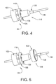
- FIG. 4 depicts a clutch support coupled to the electric motor of FIG. 3 , in accordance with an aspect of an exemplary embodiment
- FIG. 5 depicts a first clutch portion mounted to the clutch support of FIG. 4 , in accordance with an aspect of an exemplary embodiment
- FIG. 6 depicts a second clutch portion mounted to the clutch support of FIG. 5 , in accordance with an aspect of an exemplary embodiment
- FIG. 7 depicts a cantilevered end of the clutch support of FIG. 6 supported by a support fixture, in accordance with an aspect of an exemplary embodiment.
- module refers to an application specific integrated circuit (ASIC), a field programmable gate array (FPGA), an electronic circuit, an electronic computer processor (shared, dedicated, or group) and memory that executes one or more software or firmware programs, a hardware microcontroller, a combinational logic circuit, and/or other suitable components that provide the described functionality.
- ASIC application specific integrated circuit
- FPGA field programmable gate array
- a module can be embodied in memory as a non-transitory machine-readable storage medium readable by a processing circuit and storing instructions for execution by the processing circuit for performing a method.
- HIL test system 10 supports a power steering system 20 for one or more testing procedures.
- Power steering system 20 includes a power steering rack 24 having a first end 26 a second end 27 , and an intermediate portion 28 .
- An electric power steering (EPS) motor 30 is coupled to power steering rack 24 .
- EPS motor 30 includes a first end portion 31 coupled to second end 27 of power steering rack 24 and a second end portion 32 . It is to be understood that motor 32 could also be coupled to power steering rack through a shaft (not shown) or through a belt (also not shown).
- a first tie rod 34 is operatively connected to first end 26 of power steering rack 24 and a second tie rod 35 is operatively connected to second end portion 32 of EPS motor 30 .
- Each of the first tie rod 34 and the second tie rod 35 may include an associated first force transducer 36 and a second force transducer 37 .
- Power steering system 20 also includes a steering controller 40 that may selectively control EPS motor 30 during a driving maneuver.
- Steering controller 40 may include a calibration 42 that may take the form of a look-up table or a set of calibration equations that provide data for selectively controlling EPS motor 30 .
- Steering controller 40 may be operatively connected to a torque sensor 45 that provides steering feedback during the driving maneuver.
- Power steering system 20 is mounted to an HIL test fixture 60 having a test bed 62 including a first actuator 64 coupled to first tie rod 34 and a second actuator 66 coupled to second tie rod 35 .
- HIL test system 10 provides simulated steering maneuvers through first and second actuators 64 and 66 to power steering system 20 for testing, evaluation, and design of power steering components, as well as for calibrating or tuning calibration 42 .
- power steering system 20 includes a steering column, shown in the form of an intermediate shaft (I-shaft) 80 operatively connected to power steering rack 24 through an electric motor 84 .
- electric motor 84 could also be coupled along I-Shaft 80 and spaced from power steering rack 24 .
- Electric motor 84 is selectively activated to simulate steering inputs, such as would be applied by a driver or by an autonomous controller (not shown) to power steering rack 24 .
- a clutch assembly 86 is also connected to I-shaft 80 and is selectively activated to simulate hands-free steering maneuvers as will be detailed below.
- Clutch assembly 86 could be mounted to a platform 87 that may be selectively positioned upon test bed 62 through slots, one of which is indicated at 88 so as to provide n-degrees of freedom for HIL test system 10 .
- HIL test system 10 includes a calibration system 90 that simulates one or more steering maneuvers.
- Calibration system 90 includes controller 92 having a steering simulation module 93 and a memory 96 .
- Steering simulation module 93 may also include a user input 100 that may provide instructions to calibration system 90 for selectively controlling first and second actuators 64 and 66 , electric motor 84 and clutch assembly 86 to simulate one or more steering maneuvers. It is to be understood that the number of actuators may vary.
- Steering simulation module 93 may also receive inputs from first and second force transducers 36 and 37 associated with first and second tie rods 34 and 35 respectively. Steering simulation module 93 may then provide updates to calibration 42 to improve driving and steering responses.
- electric motor 84 includes a body 103 and a plurality of mechanical fasteners 105 .
- Mechanical fasteners 105 may take the form of threaded studs 108 extending from body 103 .
- a clutch support 116 may be connected to electric motor 84 as shown in FIG. 4 .
- Clutch support 116 includes a flange 118 including a plurality of openings (not separately labeled) that receive corresponding ones of mechanical fasteners 105 .
- Clutch support 116 also includes a clutch mounting zone 120 that supports a portion of clutch assembly 86 .
- clutch assembly 86 includes a first clutch portion 128 and a second clutch portion 130 ( FIG. 6 ).
- First clutch portion 128 may take the form of an energizeable member 133 that is coupled to clutch mounting zone 120 as shown in FIG. 5 . In this manner, energizeable member 133 is fixed for rotation with electric motor 84 .
- a clutch support member 138 may be provided on I-shaft 80 .
- Second clutch portion 130 is mounted to I-shaft 80 on clutch support member 138 as shown in FIG. 6 .
- Second clutch portion 130 may be fixed for rotation with I-shaft 80 .
- a support fixture 150 may be coupled to a cantilevered end portion (not separately labeled) of I-shaft 80 .
- steering simulation module 93 may activate energizeable member 133 locking electric motor 84 to I-shaft 80 .
- Steering simulation module 93 may then activate electric motor 84 to simulate a steering maneuver.
- steering simulation module 93 may selectively activate one or more of first and second actuators 64 and 66 to simulate a response to the steering maneuver. If desired, steering simulation module 93 may deactivate energizeable member 133 allowing I-shaft 80 to freely rotate to simulate a hands-free steering maneuver. Calibration system 90 may then determine how power steering system 20 responds to the steering maneuver and/or the hands-free steering maneuver to make updates to calibration 42 . The updates may then be employed in production vehicles to enhance a drivers experience with the vehicle. The updates may also be utilized by autonomous controllers to enhance driving characteristics. Additionally, the updates enhance system response to initial calibrations, reduce over-all in-vehicle development time, and make calibrations more uniform across an entire vehicle fleet by employing defined metrics. The use of HIL test system 10 allows vehicle designers to simulate driving conditions in real time without the need to construct specially outfitted test vehicles that may be monitored on a test track.
Landscapes
- Engineering & Computer Science (AREA)
- Chemical & Material Sciences (AREA)
- Combustion & Propulsion (AREA)
- Transportation (AREA)
- Mechanical Engineering (AREA)
- Physics & Mathematics (AREA)
- General Physics & Mathematics (AREA)
- Power Steering Mechanism (AREA)
Abstract
A calibration system for an electric power steering system includes a hardware-in-loop (HIL) test fixture, and an electric power steering system mounted to the HIL test fixture. The electric power steering system includes a power steering rack, and an intermediate shaft (I-shaft) mechanically connected to the power steering rack. An electric motor is operatively connected to the HIL test fixture. A clutch assembly is operatively connected between the electric motor and the I-shaft. The clutch assembly is operable to selectively connect the electric motor with the I-shaft.
Description
The subject invention relates to the art of electric power steering systems and, more particularly, to a system and method for testing hands-off clutch for a steering hardware-in-loop steering system.
A vehicle may be equipped with an electric power steering system. The electric power steering system uses an electric motor to assist a driver of the vehicle in turning the front or rear wheels of the vehicle. Sensors detect a position of a steering column and/or steering wheel, input torque, as well as current operating conditions of the vehicle. A steering controller applies an assist via the electric motor, to modify the amount of applied torque input by the driver to turn the steering wheel.
The steering controller controls the electric motor to apply the desired assist. Typically, the amount of assist input will vary with vehicle operating conditions of the vehicle. The vehicle controller may reference a calibration that relates various operating conditions of the vehicle to a desired assist. The calibration is stored in an electronic memory of the steering controller. The calibration is created to provide a desirable amount of assist or feel for the various operating conditions of the vehicle. Typically, calibration values stored in the controller are derived through various testing techniques conducted during vehicle development.
Electric power steering systems are difficult to model electronically. Accordingly, in the past, tuning the calibration for electric power steering systems has been done by installing the electric power steering system on a prototype vehicle, test driving the prototype vehicle with a defined calibration, and then adjusting the calibration based on the subjective feel observed by the test driver of the prototype vehicle. Testing through a prototype vehicle is time consuming, costly and could pose a safety concern. Further, testing through the use of a prototype vehicle could result in inconsistent calibrations. Accordingly, it is desirable to provide a system and method for bench testing and calibrating an electric power steering system.
In accordance with an exemplary aspect, a calibration system for an electric power steering system includes a hardware-in-loop (HIL) test fixture, and an electric power steering system mounted to the HIL test fixture. The electric power steering system includes a power steering rack, and an intermediate shaft (I-shaft) mechanically connected to the power steering rack. An electric motor is operatively connected to the HIL test fixture. A clutch assembly is operatively connected between the electric motor and the I-shaft. The clutch assembly is operable to selectively connect the electric motor with the I-shaft.
In addition to one or more of the features described above or below, or as an alternative, further embodiments could include wherein the clutch assembly includes a first clutch portion fixedly connected to the electric motor and a second clutch portion fixedly connected to the I-shaft.
In addition to one or more of the features described above or below, or as an alternative, further embodiments could include wherein the first clutch portion comprises an energizeable member selectively lockable to the second clutch portion.
In addition to one or more of the features described above or below, or as an alternative, further embodiments could include a clutch support operatively connected to the electric motor, the clutch support including a clutch mounting zone receptive of the energizeable member.
In addition to one or more of the features described above or below, or as an alternative, further embodiments could include a clutch support member fixedly mounted to the I-shaft receptive of the second clutch portion.
In addition to one or more of the features described above or below, or as an alternative, further embodiments could include wherein the I-shaft extends through the electric motor.
In addition to one or more of the features described above or below, or as an alternative, further embodiments could include a clutch support operatively connected to the electric motor, the clutch support including a clutch mounting zone.
In addition to one or more of the features described above or below, or as an alternative, further embodiments could include wherein the power steering rack includes a first end, a second end, and an intermediate portion extending therebetween and being coupled to the HIL test fixture, the I-shaft being operatively coupled to the intermediate portion.
In addition to one or more of the features described above or below, or as an alternative, further embodiments could include an electric power steering (EPS) motor including a first end portion operatively coupled to the first end of the power steering rack and a second end portion.
In addition to one or more of the features described above or below, or as an alternative, further embodiments could include a first tie rod operatively connected to the second end of the power steering rack and a second tie rod operatively coupled to the second end portion of the EPS motor.
In addition to one or more of the features described above or below, or as an alternative, further embodiments could include a first actuator operatively coupled to the first tie rod and a second actuator operatively coupled to the second tie rod, the first and second actuators being operable to act upon one or more of the first and second tie rods to simulate vehicle operation.
In accordance with another aspect of an exemplary embodiment, a method of tuning a calibration for an electric power steering system includes energizing a clutch assembly to operatively connect a steering column to an electric motor, activating the electric motor to rotate the steering column to simulate a steering maneuver, denergizing the clutch assembly to simulate a hands-free steering maneuver, and sensing a steering response in the electric power steering system during one of the steering maneuver and the hands-free steering maneuver.
In addition to one or more of the features described above or below, or as an alternative, further embodiments could include collecting data during the one of the steering maneuver and the hands-free steering maneuver, and updating a calibration of the electric power steering system based on the data.
In addition to one or more of the features described above or below, or as an alternative, further embodiments could include inputting one or more forces to a tie rod of the electric power steering system to simulate driving conditions during the steering maneuver.
In addition to one or more of the features described above or below, or as an alternative, further embodiments could include inputting one or more forces to a tie rod of the electric power steering system to simulate driving conditions during the hands-free steering maneuver.
The above features and advantages and other features and advantages of the invention are readily apparent from the following detailed description of the invention when taken in connection with the accompanying drawings.
Other features, advantages and details appear, by way of example only, in the following detailed description of embodiments, the detailed description referring to the drawings in which:
The following description is merely exemplary in nature and is not intended to limit the present disclosure, its application or uses. It should be understood that throughout the drawings, corresponding reference numerals indicate like or corresponding parts and features. As used herein, the term “module” or “unit” refers to an application specific integrated circuit (ASIC), a field programmable gate array (FPGA), an electronic circuit, an electronic computer processor (shared, dedicated, or group) and memory that executes one or more software or firmware programs, a hardware microcontroller, a combinational logic circuit, and/or other suitable components that provide the described functionality. When implemented in software, a module can be embodied in memory as a non-transitory machine-readable storage medium readable by a processing circuit and storing instructions for execution by the processing circuit for performing a method.
A hardware-in-loop (HIL) test system, in accordance with an exemplary embodiment, is indicated generally at 10 in FIG. 1 . HIL test system 10 supports a power steering system 20 for one or more testing procedures. Power steering system 20 includes a power steering rack 24 having a first end 26 a second end 27, and an intermediate portion 28. An electric power steering (EPS) motor 30 is coupled to power steering rack 24. More specifically, EPS motor 30 includes a first end portion 31 coupled to second end 27 of power steering rack 24 and a second end portion 32. It is to be understood that motor 32 could also be coupled to power steering rack through a shaft (not shown) or through a belt (also not shown). A first tie rod 34 is operatively connected to first end 26 of power steering rack 24 and a second tie rod 35 is operatively connected to second end portion 32 of EPS motor 30. Each of the first tie rod 34 and the second tie rod 35 may include an associated first force transducer 36 and a second force transducer 37.
In accordance with an aspect of an exemplary embodiment, power steering system 20 includes a steering column, shown in the form of an intermediate shaft (I-shaft) 80 operatively connected to power steering rack 24 through an electric motor 84. It is to be understood that electric motor 84 could also be coupled along I-Shaft 80 and spaced from power steering rack 24. Electric motor 84 is selectively activated to simulate steering inputs, such as would be applied by a driver or by an autonomous controller (not shown) to power steering rack 24. A clutch assembly 86 is also connected to I-shaft 80 and is selectively activated to simulate hands-free steering maneuvers as will be detailed below. Clutch assembly 86 could be mounted to a platform 87 that may be selectively positioned upon test bed 62 through slots, one of which is indicated at 88 so as to provide n-degrees of freedom for HIL test system 10.
As shown in FIG. 2 and with continuing reference to FIG. 1 , HIL test system 10 includes a calibration system 90 that simulates one or more steering maneuvers. Calibration system 90 includes controller 92 having a steering simulation module 93 and a memory 96. Steering simulation module 93 may also include a user input 100 that may provide instructions to calibration system 90 for selectively controlling first and second actuators 64 and 66, electric motor 84 and clutch assembly 86 to simulate one or more steering maneuvers. It is to be understood that the number of actuators may vary. Steering simulation module 93 may also receive inputs from first and second force transducers 36 and 37 associated with first and second tie rods 34 and 35 respectively. Steering simulation module 93 may then provide updates to calibration 42 to improve driving and steering responses.
Reference will now follow to FIGS. 3-7 in describing details of electric motor 84 and clutch assembly 86. As shown in FIG. 3 , electric motor 84 includes a body 103 and a plurality of mechanical fasteners 105. Mechanical fasteners 105 may take the form of threaded studs 108 extending from body 103. A clutch support 116 may be connected to electric motor 84 as shown in FIG. 4 . Clutch support 116 includes a flange 118 including a plurality of openings (not separately labeled) that receive corresponding ones of mechanical fasteners 105. Clutch support 116 also includes a clutch mounting zone 120 that supports a portion of clutch assembly 86. More specifically, clutch assembly 86 includes a first clutch portion 128 and a second clutch portion 130 (FIG. 6 ). First clutch portion 128 may take the form of an energizeable member 133 that is coupled to clutch mounting zone 120 as shown in FIG. 5 . In this manner, energizeable member 133 is fixed for rotation with electric motor 84.
In further accordance with an exemplary aspect, a clutch support member 138 may be provided on I-shaft 80. Second clutch portion 130 is mounted to I-shaft 80 on clutch support member 138 as shown in FIG. 6 . Second clutch portion 130 may be fixed for rotation with I-shaft 80. After mounting clutch assembly 86, a support fixture 150 may be coupled to a cantilevered end portion (not separately labeled) of I-shaft 80. With this arrangement, steering simulation module 93 may activate energizeable member 133 locking electric motor 84 to I-shaft 80. Steering simulation module 93 may then activate electric motor 84 to simulate a steering maneuver.
In addition, steering simulation module 93 may selectively activate one or more of first and second actuators 64 and 66 to simulate a response to the steering maneuver. If desired, steering simulation module 93 may deactivate energizeable member 133 allowing I-shaft 80 to freely rotate to simulate a hands-free steering maneuver. Calibration system 90 may then determine how power steering system 20 responds to the steering maneuver and/or the hands-free steering maneuver to make updates to calibration 42. The updates may then be employed in production vehicles to enhance a drivers experience with the vehicle. The updates may also be utilized by autonomous controllers to enhance driving characteristics. Additionally, the updates enhance system response to initial calibrations, reduce over-all in-vehicle development time, and make calibrations more uniform across an entire vehicle fleet by employing defined metrics. The use of HIL test system 10 allows vehicle designers to simulate driving conditions in real time without the need to construct specially outfitted test vehicles that may be monitored on a test track.
While the above disclosure has been described with reference to exemplary embodiments, it will be understood by those skilled in the art that various changes may be made and equivalents may be substituted for elements thereof without departing from its scope. In addition, many modifications may be made to adapt a particular situation or material to the teachings of the disclosure without departing from the essential scope thereof. Therefore, it is intended that the invention not be limited to the particular embodiments disclosed, but will include all embodiments falling within the scope of the application.
Claims (14)
1. A calibration system for an electric power steering system comprising:
a hardware-in-loop (HIL) test fixture;
an electric power steering system mounted to the HIL test fixture, the electric power steering system including a power steering rack, and an intermediate shaft (I-shaft) mechanically connected to the power steering rack;
an electric motor operatively connected to the HIL test fixture;
a clutch support operatively connected to the electric motor, the clutch support including a clutch mounting zone; and
a clutch assembly operatively connected to the clutch mounting zone between the electric motor and the I-shaft, the clutch assembly being operable to selectively connect the electric motor with the I-shaft.
2. The calibration system according to claim 1 , wherein the clutch assembly includes a first clutch portion fixedly connected to the electric motor and a second clutch portion fixedly connected to the I-shaft.
3. The calibration system according to claim 2 , wherein the first clutch portion comprises an energizeable member selectively lockable to the second clutch portion.
4. The calibration system according to claim 3 , further comprising: a clutch support operatively connected to the electric motor, the clutch support including a clutch mounting zone receptive of the energizeable member.
5. The calibration system according to claim 4 , further comprising: a clutch support member fixedly mounted to the I-shaft receptive of the second clutch portion.
6. The calibration system according to claim 1 , wherein the I-shaft extends through the electric motor.
7. The calibration system according to claim 1 , wherein the power steering rack includes a first end, a second end, and an intermediate portion extending therebetween and being coupled to the HIL test fixture, the I-shaft being operatively coupled to the intermediate portion.
8. The calibration system according to claim 7 , further comprising: an electric power steering (EPS) motor including a first end portion operatively coupled to the first end of the power steering rack and a second end portion.
9. The calibration system according to claim 8 , further comprising: a first tie rod operatively connected to the second end of the power steering rack and a second tie rod operatively coupled to the second end portion of the EPS motor.
10. The calibration system according to claim 9 , further comprising: a first actuator operatively coupled to the first tie rod and a second actuator operatively coupled to the second tie rod, the first and second actuators being operable to act upon one or more of the first and second tie rods to simulate vehicle operation.
11. A method of tuning a calibration for an electric power steering system comprising:
energizing a clutch assembly to operatively connect a steering column to an electric motor;
activating the electric motor to rotate the steering column to simulate a steering maneuver;
de-energizing the clutch assembly to simulate a hands-free steering maneuver; and
sensing a steering response in the electric power steering system during each of the steering maneuver and the hands-free steering maneuver.
12. The method of claim 11 , further comprising:
collecting data during the one of the steering maneuver and the hands-free steering maneuver; and
updating a calibration of the electric power steering system based on the data.
13. The method of claim 11 , further comprising: inputting one or more forces to a tie rod of the electric power steering system to simulate driving conditions during the steering maneuver.
14. The method of claim 11 , further comprising: inputting one or more forces to a tie rod of the electric power steering system to simulate driving conditions during the hands-free steering maneuver.
Priority Applications (1)
| Application Number | Priority Date | Filing Date | Title |
|---|---|---|---|
| US15/464,982 US10093345B1 (en) | 2017-03-21 | 2017-03-21 | System and method for testing a hands-off clutch for a steering hardware-in-loop (HIL) system |
Applications Claiming Priority (1)
| Application Number | Priority Date | Filing Date | Title |
|---|---|---|---|
| US15/464,982 US10093345B1 (en) | 2017-03-21 | 2017-03-21 | System and method for testing a hands-off clutch for a steering hardware-in-loop (HIL) system |
Publications (2)
| Publication Number | Publication Date |
|---|---|
| US20180273084A1 US20180273084A1 (en) | 2018-09-27 |
| US10093345B1 true US10093345B1 (en) | 2018-10-09 |
Family
ID=63582154
Family Applications (1)
| Application Number | Title | Priority Date | Filing Date |
|---|---|---|---|
| US15/464,982 Active US10093345B1 (en) | 2017-03-21 | 2017-03-21 | System and method for testing a hands-off clutch for a steering hardware-in-loop (HIL) system |
Country Status (1)
| Country | Link |
|---|---|
| US (1) | US10093345B1 (en) |
Cited By (1)
| Publication number | Priority date | Publication date | Assignee | Title |
|---|---|---|---|---|
| US12379288B2 (en) | 2023-04-06 | 2025-08-05 | GM Global Technology Operations LLC | Systems and methods for testing damping modules |
Families Citing this family (5)
| Publication number | Priority date | Publication date | Assignee | Title |
|---|---|---|---|---|
| USD852684S1 (en) | 2017-02-18 | 2019-07-02 | Aircraft Gear Corporation | Shaft |
| CN111006885B (en) * | 2019-12-12 | 2021-11-23 | 北京经纬恒润科技股份有限公司 | Method and device for calibrating EPS (electric power steering) model parameters of electric power steering system |
| WO2022051909A1 (en) * | 2020-09-08 | 2022-03-17 | 华为技术有限公司 | Steering mechanism, steering system, vehicle, and control method for steering system |
| CN113238933B (en) * | 2021-04-30 | 2024-03-12 | 阿波罗智联(北京)科技有限公司 | Chassis simulation method, device, server, storage medium and program product |
| CN113588298B (en) * | 2021-09-29 | 2022-01-21 | 山东天河科技股份有限公司 | Test system for vehicle steering performance |
Citations (14)
| Publication number | Priority date | Publication date | Assignee | Title |
|---|---|---|---|---|
| US3251142A (en) * | 1962-05-21 | 1966-05-17 | Aetna Casualty And Surety Comp | Simulator |
| US4141256A (en) * | 1977-01-17 | 1979-02-27 | Mattel, Inc. | Two-speed inertia motor |
| US5027276A (en) * | 1988-04-14 | 1991-06-25 | Mitsubishi Denki K.K. | Electric power steering device having a fail-safe relay |
| US5027915A (en) * | 1987-12-26 | 1991-07-02 | Aisin Seiki Kabushiki Kaisha | Electric power steering system |
| US5670854A (en) * | 1994-12-14 | 1997-09-23 | Matsushita Electric Industrial Co., Ltd. | Control system for an induction motor |
| US5836419A (en) * | 1994-12-21 | 1998-11-17 | Honda Giken Kogyo Kabushiki | Rack and pinion electric power steering system with unitized construction for removable mounting |
| US20040237517A1 (en) * | 2001-04-17 | 2004-12-02 | Chol-Seung Cho | Phev (pneumatic hybrid electric vehicle) |
| US20070119649A1 (en) * | 2005-11-30 | 2007-05-31 | Jungheinrich Aktiengsellschaft | Drive and steering unit for a wheel of a floor conveyor |
| US20130030652A1 (en) * | 2011-07-28 | 2013-01-31 | Hyundai Motor Company | Device combining motor driven power steering with compressor, and method for controlling the same |
| US8567262B2 (en) * | 2010-03-31 | 2013-10-29 | Honda Motor Co., Ltd. | Electric power steering apparatus for saddle-ride type vehicle |
| CN203854717U (en) * | 2014-05-23 | 2014-10-01 | 河南速达电动汽车科技有限公司 | Electric power steering system |
| US20160009311A1 (en) * | 2014-07-09 | 2016-01-14 | ZF Steering Systems, LLC | Friction clutch for steering column |
| US20170174259A1 (en) * | 2015-12-22 | 2017-06-22 | Uber Technologies, Inc. | Integrated clutch steering system |
| CN206421648U (en) * | 2017-01-25 | 2017-08-18 | 安徽机电职业技术学院 | Automobile electric booster steering system experimental real-training stand |
-
2017
- 2017-03-21 US US15/464,982 patent/US10093345B1/en active Active
Patent Citations (14)
| Publication number | Priority date | Publication date | Assignee | Title |
|---|---|---|---|---|
| US3251142A (en) * | 1962-05-21 | 1966-05-17 | Aetna Casualty And Surety Comp | Simulator |
| US4141256A (en) * | 1977-01-17 | 1979-02-27 | Mattel, Inc. | Two-speed inertia motor |
| US5027915A (en) * | 1987-12-26 | 1991-07-02 | Aisin Seiki Kabushiki Kaisha | Electric power steering system |
| US5027276A (en) * | 1988-04-14 | 1991-06-25 | Mitsubishi Denki K.K. | Electric power steering device having a fail-safe relay |
| US5670854A (en) * | 1994-12-14 | 1997-09-23 | Matsushita Electric Industrial Co., Ltd. | Control system for an induction motor |
| US5836419A (en) * | 1994-12-21 | 1998-11-17 | Honda Giken Kogyo Kabushiki | Rack and pinion electric power steering system with unitized construction for removable mounting |
| US20040237517A1 (en) * | 2001-04-17 | 2004-12-02 | Chol-Seung Cho | Phev (pneumatic hybrid electric vehicle) |
| US20070119649A1 (en) * | 2005-11-30 | 2007-05-31 | Jungheinrich Aktiengsellschaft | Drive and steering unit for a wheel of a floor conveyor |
| US8567262B2 (en) * | 2010-03-31 | 2013-10-29 | Honda Motor Co., Ltd. | Electric power steering apparatus for saddle-ride type vehicle |
| US20130030652A1 (en) * | 2011-07-28 | 2013-01-31 | Hyundai Motor Company | Device combining motor driven power steering with compressor, and method for controlling the same |
| CN203854717U (en) * | 2014-05-23 | 2014-10-01 | 河南速达电动汽车科技有限公司 | Electric power steering system |
| US20160009311A1 (en) * | 2014-07-09 | 2016-01-14 | ZF Steering Systems, LLC | Friction clutch for steering column |
| US20170174259A1 (en) * | 2015-12-22 | 2017-06-22 | Uber Technologies, Inc. | Integrated clutch steering system |
| CN206421648U (en) * | 2017-01-25 | 2017-08-18 | 安徽机电职业技术学院 | Automobile electric booster steering system experimental real-training stand |
Cited By (1)
| Publication number | Priority date | Publication date | Assignee | Title |
|---|---|---|---|---|
| US12379288B2 (en) | 2023-04-06 | 2025-08-05 | GM Global Technology Operations LLC | Systems and methods for testing damping modules |
Also Published As
| Publication number | Publication date |
|---|---|
| US20180273084A1 (en) | 2018-09-27 |
Similar Documents
| Publication | Publication Date | Title |
|---|---|---|
| US10093345B1 (en) | System and method for testing a hands-off clutch for a steering hardware-in-loop (HIL) system | |
| US10489993B2 (en) | Emulator hardware-in-loop architecture and control logic for vehicle steer-by-wire test system | |
| CN102602452B (en) | For the method for the non-manual driving condition for detecting motor vehicles | |
| CN111417563A (en) | Method for controlling a steer-by-wire system with active return functionality | |
| US9909954B2 (en) | System and method to quantify viscous damping steering feel of a vehicle equipped with an electric power steering system | |
| WO2016208399A1 (en) | Vehicular steering device having automatic steering function | |
| WO2003010505A1 (en) | Tire testing machine for real time evaluation of steering stability | |
| US20180357338A1 (en) | Kinematics table generation for steering hardware simulator | |
| CN110626420A (en) | Driver Notification Using Handheld Steering Wheel Actuators in Steer-by-Wire Systems | |
| US20230109469A1 (en) | Method for operating an electromechanically assisted steering system | |
| JP2021505460A (en) | Use of assist motors in power steering systems to generate test cycles with force confirmation cycles | |
| CN109720405A (en) | Motor drive power steering system and its control method | |
| JP2011063130A (en) | Control parameter adaptation device | |
| CN111565997A (en) | Method for configuring and controlling a steering system, steering system and vehicle | |
| JP2005212706A (en) | Electric power steering evaluation system, method, and program | |
| JP2022082002A (en) | Automotive test system and actual road driving simulator | |
| US20230242177A1 (en) | Electric power steering system | |
| TW202225005A (en) | Steering control device and control method for wire-controlled vehicle | |
| JP2007238070A (en) | Electric variable gear transmission device and electric power steering device control device | |
| US9150243B2 (en) | Harmonic pinion torque correction | |
| JP4793576B2 (en) | Steering device test system | |
| WO2007075291A1 (en) | Torque sensor based steering response | |
| JP2008247119A (en) | Operation support device for vehicle | |
| EP2497697A2 (en) | Damping methods and systems for electric power steering | |
| CN105966453B (en) | Torque steering for electric power steering slows down |
Legal Events
| Date | Code | Title | Description |
|---|---|---|---|
| AS | Assignment |
Owner name: GM GLOBAL TECHNOLOGY OPERATIONS LLC, MICHIGAN Free format text: ASSIGNMENT OF ASSIGNORS INTEREST;ASSIGNORS:DICKSON, WILLIAM F.;KONIECZNY, THEODORE P.;RONALD, AARON;SIGNING DATES FROM 20170316 TO 20170317;REEL/FRAME:041666/0815 |
|
| STCF | Information on status: patent grant |
Free format text: PATENTED CASE |
|
| MAFP | Maintenance fee payment |
Free format text: PAYMENT OF MAINTENANCE FEE, 4TH YEAR, LARGE ENTITY (ORIGINAL EVENT CODE: M1551); ENTITY STATUS OF PATENT OWNER: LARGE ENTITY Year of fee payment: 4 |