US10091495B2 - Apparatus and method for displaying stereoscopic images - Google Patents
Apparatus and method for displaying stereoscopic images Download PDFInfo
- Publication number
- US10091495B2 US10091495B2 US14/654,804 US201214654804A US10091495B2 US 10091495 B2 US10091495 B2 US 10091495B2 US 201214654804 A US201214654804 A US 201214654804A US 10091495 B2 US10091495 B2 US 10091495B2
- Authority
- US
- United States
- Prior art keywords
- image
- border
- depth
- pixels
- stereo
- Prior art date
- Legal status (The legal status is an assumption and is not a legal conclusion. Google has not performed a legal analysis and makes no representation as to the accuracy of the status listed.)
- Expired - Fee Related, expires
Links
Images


Classifications
-
- H—ELECTRICITY
- H04—ELECTRIC COMMUNICATION TECHNIQUE
- H04N—PICTORIAL COMMUNICATION, e.g. TELEVISION
- H04N13/00—Stereoscopic video systems; Multi-view video systems; Details thereof
- H04N13/30—Image reproducers
-
- H04N13/0018—
-
- H04N13/0022—
-
- H04N13/004—
-
- H04N13/04—
-
- H—ELECTRICITY
- H04—ELECTRIC COMMUNICATION TECHNIQUE
- H04N—PICTORIAL COMMUNICATION, e.g. TELEVISION
- H04N13/00—Stereoscopic video systems; Multi-view video systems; Details thereof
- H04N13/10—Processing, recording or transmission of stereoscopic or multi-view image signals
- H04N13/106—Processing image signals
- H04N13/122—Improving the 3D impression of stereoscopic images by modifying image signal contents, e.g. by filtering or adding monoscopic depth cues
-
- H—ELECTRICITY
- H04—ELECTRIC COMMUNICATION TECHNIQUE
- H04N—PICTORIAL COMMUNICATION, e.g. TELEVISION
- H04N13/00—Stereoscopic video systems; Multi-view video systems; Details thereof
- H04N13/10—Processing, recording or transmission of stereoscopic or multi-view image signals
- H04N13/106—Processing image signals
- H04N13/128—Adjusting depth or disparity
-
- H—ELECTRICITY
- H04—ELECTRIC COMMUNICATION TECHNIQUE
- H04N—PICTORIAL COMMUNICATION, e.g. TELEVISION
- H04N13/00—Stereoscopic video systems; Multi-view video systems; Details thereof
- H04N13/10—Processing, recording or transmission of stereoscopic or multi-view image signals
- H04N13/106—Processing image signals
- H04N13/156—Mixing image signals
-
- H—ELECTRICITY
- H04—ELECTRIC COMMUNICATION TECHNIQUE
- H04N—PICTORIAL COMMUNICATION, e.g. TELEVISION
- H04N21/00—Selective content distribution, e.g. interactive television or video on demand [VOD]
- H04N21/40—Client devices specifically adapted for the reception of or interaction with content, e.g. set-top-box [STB]; Operations thereof
- H04N21/43—Processing of content or additional data, e.g. demultiplexing additional data from a digital video stream; Elementary client operations, e.g. monitoring of home network or synchronising decoder's clock; Client middleware
- H04N21/431—Generation of visual interfaces for content selection or interaction; Content or additional data rendering
-
- H—ELECTRICITY
- H04—ELECTRIC COMMUNICATION TECHNIQUE
- H04N—PICTORIAL COMMUNICATION, e.g. TELEVISION
- H04N21/00—Selective content distribution, e.g. interactive television or video on demand [VOD]
- H04N21/80—Generation or processing of content or additional data by content creator independently of the distribution process; Content per se
- H04N21/81—Monomedia components thereof
- H04N21/816—Monomedia components thereof involving special video data, e.g 3D video
-
- H—ELECTRICITY
- H04—ELECTRIC COMMUNICATION TECHNIQUE
- H04N—PICTORIAL COMMUNICATION, e.g. TELEVISION
- H04N5/00—Details of television systems
- H04N5/44—Receiver circuitry for the reception of television signals according to analogue transmission standards
- H04N5/445—Receiver circuitry for the reception of television signals according to analogue transmission standards for displaying additional information
- H04N5/45—Picture in picture, e.g. displaying simultaneously another television channel in a region of the screen
-
- H—ELECTRICITY
- H04—ELECTRIC COMMUNICATION TECHNIQUE
- H04N—PICTORIAL COMMUNICATION, e.g. TELEVISION
- H04N13/00—Stereoscopic video systems; Multi-view video systems; Details thereof
- H04N2013/0074—Stereoscopic image analysis
- H04N2013/0081—Depth or disparity estimation from stereoscopic image signals
-
- H—ELECTRICITY
- H04—ELECTRIC COMMUNICATION TECHNIQUE
- H04N—PICTORIAL COMMUNICATION, e.g. TELEVISION
- H04N21/00—Selective content distribution, e.g. interactive television or video on demand [VOD]
- H04N21/40—Client devices specifically adapted for the reception of or interaction with content, e.g. set-top-box [STB]; Operations thereof
- H04N21/43—Processing of content or additional data, e.g. demultiplexing additional data from a digital video stream; Elementary client operations, e.g. monitoring of home network or synchronising decoder's clock; Client middleware
- H04N21/431—Generation of visual interfaces for content selection or interaction; Content or additional data rendering
- H04N21/4312—Generation of visual interfaces for content selection or interaction; Content or additional data rendering involving specific graphical features, e.g. screen layout, special fonts or colors, blinking icons, highlights or animations
- H04N21/4316—Generation of visual interfaces for content selection or interaction; Content or additional data rendering involving specific graphical features, e.g. screen layout, special fonts or colors, blinking icons, highlights or animations for displaying supplemental content in a region of the screen, e.g. an advertisement in a separate window
Definitions
- the disclosed invention generally relates to displaying contents and more specifically relates to a picture-in-picture display technique capable of presenting a plurality of three-dimensional images on a display at the same time.
- PIP picture-in-picture
- the TV system can display the two programs on the single screen of the TV.
- the view of the basketball game occupies a larger part of the screen or even the complete screen so that the user can watch more details, while the football game is displayed in a smaller window on the lower-right corner of the screen, which is beside or in the display zone of the basketball game.
- the view of the basketball game is the main image while the view of the football game is the sub-image.
- FIG. 1 shows an image provided by a TV in a 2D PIP mode.
- a main image 102 and a sub-image 103 are simultaneously displayed on a TV set 101 in the 2D PIP mode.
- Such a PIP function may satisfy user's demands to simultaneously view a plurality of images on a single screen.
- stereoscopic display techniques have been developed recently, such as space-multiplexed polarization type stereoscopic display techniques (polarized glasses required), time-multiplexed light valve type stereoscopic display techniques (light valve glasses required), multiple-view stereoscopic display techniques that do not require any stereoscopic glasses, etc.
- the aforementioned stereoscopic display techniques are all based on the principle of stereoscopic vision of human eyes, and efforts are made to improve display hardware and image processing software, so that an image intended for viewing with the left eye enters the left eye of a viewer and an image intended for viewing with the right eye enters the right eye of the viewer to thereby produce a stereoscopic picture in the brain of the viewer.
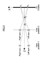
- FIG. 2 shows an exemplary concept illustration of a 3D stereoscopic display.
- Z represents the depth direction of a perceived object
- D represents the distance to the screen.
- Most modern 3D displays are built based on 3D stereo concepts, with the major difference on how to separate the two views to left and right eyes, respectively.
- the perceived depth of a given point becomes smaller or larger, shown as the perceived point P 1 and P 2 in FIG. 3 corresponding to view positions 1 and 2 for the same displayed stereoscopic points P L and P R on the 3D display. Therefore, the disparity, i.e. the distance between P L and P R , is used to replace the depth in many technical documents for a more accurate description. However, the depth is still used at many cases for easy understanding.
- one object of the present invention is to provide some techniques for displaying a stereoscopic view in a 2D PIP mode.
- a stereoscopic display apparatus comprising: a stereo image acquisition unit configured to acquire a first stereo image for a first image and a second stereo image for a second image; a border generation unit configured to generate a border for separating the first image from the second image; and a displaying unit configured to combine the second stereo image and the generated border with the first stereo image and display the combined stereo images.
- Another aspect of the disclosed invention relates to a method for displaying a stereo image, comprising: acquiring a first stereo image for a first image and a second stereo image for a second image; generating a border for separating the first image from the second image; combining the second stereo image and the generated border with the first stereo image; and displaying the combined stereo images.
- FIG. 1 shows an image provided by a TV in a 2D PIP mode
- FIG. 2 shows an exemplary concept illustration of 3D stereoscopic display
- FIG. 3 shows an exemplary illustration of different 3D depth values viewing from different distances
- FIGS. 4A and 4B show exemplary arrangements of main images and sub-images
- FIGS. 5A and 5B show exemplary borders provided between main images and sub-images
- FIG. 6 shows an exemplary arrangement of a stereoscopic display apparatus according to one embodiment of the present invention
- FIG. 7 shows a flowchart illustrating an exemplary method for displaying a stereo image according to one embodiment of the present invention
- FIG. 8 shows a flowchart illustrating an exemplary method for displaying a stereo image according to one embodiment of the present invention
- FIG. 9 shows an exemplary linear mapping between depth of pixels and coordinates thereof
- FIGS. 10A and 10B show an exemplary case where a part of a border horizontally separates two images.
- FIG. 11 shows a flowchart illustrating an exemplary method for displaying a stereo image according to one embodiment of the present invention
- FIG. 12 shows an exemplary stereoscopic view according to one embodiment of the present invention.
- FIGS. 13A and 13B show left and right views of a stereoscopic view according to one embodiment of the present invention
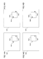
- FIGS. 14A-14D show left and right views of a stereoscopic view according to one embodiment of the present invention.
- FIG. 15 shows a flowchart illustrating an exemplary method for displaying a stereo image according to one embodiment of the present invention.
- FIG. 4 In traditional 2D PIP applications, a plurality of pictures are displayed as picture in picture or picture by picture, as shown in FIG. 4 .
- a sub-image 202 is displayed in the display zone of a main image 201
- a sub-image 203 is displayed in the lower-right corner of the display zone of the main image 201 .
- a main image 211 , a sub-image 212 , and a sub-image 213 are displayed side by side.
- an additional border is added to separate the two images.
- an additional border 312 is used to separate a main image 301 and a sub-image 302 .
- the border should be wide enough so that viewers can easily distinguish the content in the main image 301 from that in the sub-image 302 .
- the border 312 can be any color, or a combination of colors, or a strip of picture.
- a 2D border may be used.
- a 3D border may be used.
- the depth of the 3D border may be constant.
- the depth of the 3D border may change dynamically according to the depth of the content adjacent to the border.
- a stereoscopic display apparatus is described in detail below.
- an additional border is added to separate two images, first and second images, so that viewers may easily distinguish the contents between the first image and the second image in a 3D space.
- the first image may serve as a main image
- the second image may serve as a sub-image in a PIP display mode.
- the stereoscopic display apparatus may be a TV set, a personal computer, a smart phone, a tablet or any other apparatus including a display device for displaying data or information.
- FIG. 6 shows an exemplary arrangement of a stereoscopic display apparatus according to one embodiment of the present invention.
- a stereoscopic display apparatus 100 includes a stereo image acquisition unit 110 , a border generation unit 120 and a displaying unit 130 .
- the stereo image acquisition unit 110 acquires a first stereo image for a first image and a second stereo image for a second image from internal or external sources 115 .
- the first and second images may serve as a main image and a sub-image in a PIP mode, respectively.
- the stereo image acquisition unit 110 may further acquire depth information or a depth map for the stereo images together.
- the border generation unit 120 generates a border for separating the first image from the second image.
- the border generation unit 120 includes a border region determination unit 121 and a border depth determination unit 122 .
- the border region determination unit 121 determines a border region including contents adjacent to the border.
- the border region has a width of pixels around the border.
- the border region may include a predetermined number of pixels in the first and second stereo images adjacent to the border.
- the border region consists of some pixels in the first stereo image, the border itself and some pixels in the second stereo image.
- the border depth determination unit 122 generates the border region with depth information by determining depth of pixels in the border region based on coordinates of the respective pixels and a depth range of the pixels in the border region.
- the border region having the depth information the stereoscopic display apparatus 100 can display the border three-dimensionally, for example, by displaying the border like a wall having a width and a height.
- the displaying unit 130 combines the second stereo image and the generated border with the first stereo image and displays the combined stereo images on a display device 135 .
- FIG. 7 shows a flowchart illustrating an exemplary method for displaying a stereo image according to one embodiment of the present invention.
- the stereo image acquisition unit 110 acquires a first stereo image for a first image from an internal or external source.
- the stereo image acquisition unit 110 acquires a second stereo image for a second image from the internal or external source.
- the border generation unit 120 generates a border for separating the first image from the second image in a PIP mode.
- the border may be the border itself or consist of a border region as stated above.
- the displaying unit 130 combines the first image, the second image and the border or the border region. For example, the displaying unit 130 may superimpose the second image and the border or the border region onto predetermined positions in the first image.
- the displaying unit 130 displays the combined stereo image on a display device.
- a stereoscopic display apparatus is described with reference to FIGS. 8-10 .
- a 3D border having a depth changing dynamically based on the depth of adjacent contents in first and second images is used.
- FIG. 8 is a flowchart showing an exemplary method for dynamically changing the depth of a 3D border according to one embodiment of the present invention.
- stereo images are obtained both for a main image and a sub-image.
- imagery contents they can be pairs of images for left and right eye views.
- a 3D model and a rendering method (including camera separation and focal length) are obtained.
- contents adjacent to a border between the main image and the sub-image are determined.
- a narrow or broad region between contents 311 in the main image 301 and contents 313 in the sub-image 302 adjacent to the border 312 is determined.
- the contents 311 may be determined as an outer area in the main image 301 externally surrounding the border 312 with a thickness of a predetermined number of pixels from the border 312 .
- the contents 313 may be determined as an inner area in the sub-image 302 internally surrounding the border 312 with a thickness of a predetermined number of pixels from the border 312 .
- the narrow region may be determined as an area consisting of the contents 311 , the border 312 and the contents 313 .
- the thickness of the contents 311 and 313 may be dynamically determined, for example, depending on the display size and/or similarity of the contents 311 and 313 .
- the thickness of the contents 311 and 313 may be adjusted through user's manipulation. If the user cannot successfully distinguish the main image 301 and the sub-image 302 , the thickness of the contents 311 and 313 may be set to be greater.
- the determination of the narrow region according to the present invention is not limited to it, and any other appropriate determination method may be applied.
- a depth map for the contents 311 and 313 adjacent to the border 312 in both the main image 301 and the sub-image 302 is obtained.
- the depth map may be obtained in any appropriate conventional method. For imagery contents, the depth of each pixel may be recorded at the time of capture. If a stereo image pair has been captured without depth information, there are several existing methods in the prior art to obtain this depth map, including block matching and phase correlation. For contents that are generated using computer graphics, the depth map can be obtained through analytical calculation, given the knowledge of the 3D model and the rendering method.
- a depth range for the contents 311 and 313 adjacent to the border is calculated. As shown in FIG. 9 , the depth range indicates the minimum depth d min and the maximum depth d max of the contents 311 and 313 adjacent to the border 312 .
- the depth map of the border 312 is determined at Step 404 .
- FIG. 9 shows an example of linear mapping between the depth and the coordinate of pixels.
- FIGS. 10A and 10B show a case where a part of the border 610 horizontally separates two images. For a pixel 620 on the border 610 that horizontally separates a main image 601 and a sub-image 602 , the depth d of the pixel 620 can be calculated by its x-coordinate x as:
- x min and x max are the minimum and maximum x-coordinates, respectively, of pixels on the horizontal line 630
- d min and d max are the minimum and maximum depth values, respectively, in the depth range obtained at Step 403 .
- the part of the border 610 will look like a wall between the two images, as shown in FIG. 10B , which will prevent viewers from confusing contents of the main image 601 with those of the sub-image 602 .
- Step 405 the additional border looking like the wall to the viewers is rendered and displayed according to the depth map obtained at Step 404 .
- a stereoscopic display apparatus is described with reference to FIGS. 11-12 .
- the depth of a sub-image is adjusted dynamically to make sure that all pixels of a main image around the sub-image are always behind or in front of the pixels of the sub-image adjacent to the border.
- there is an obvious depth change on the border of the two images so that viewers won't confuse the contents of one image with that of another image.
- the depth of the sub-image 602 is adjusted dynamically to make sure that all pixels of the main image 601 around the sub-image 602 are always behind or in front of the pixels of the sub-image 602 adjacent to the border 610 .
- there is an obvious depth change on the border 610 of the two images so that viewers won't confuse the contents of one image with that of another image.
- FIG. 11 shows a flow chart of an exemplary method for dynamically changing the depth of a 3D border according to another embodiment of the present invention.
- stereo images are obtained both for a main image and a sub-image, respectively.
- imagery content they can be pairs of images for left and right eye views.
- a 3D model and a rendering method are obtained.
- contents adjacent to a border between the main image and the sub-image are determined, respectively.
- a narrow region of contents 811 in the main image 801 and contents 813 in the sub-image 802 is determined.
- depth maps for the contents 811 and 813 of the border regions of the two images are obtained, respectively.
- the depth of each pixel may be recorded at the time of capture. If a stereo image pair has been captured without depth information, there are several existing methods in the prior art to obtain the depth maps, including block matching and phase correlation.
- the depth map can be obtained through analytical calculation, given the knowledge of a 3D model and a rendering method.
- the depth ranges for the contents 811 and 813 of the border regions of the two images are calculated, respectively.
- the depth range for the border region of the main image 801 is defined by the minimum depth d main _ min and the maximum depth d main _ max
- the depth range for the border region of the sub-image 802 is defined by the minimum depth d sub _ min and the maximum depth d sub _ max .
- the amount of depth adjustment ⁇ is determined based on a threshold of depth difference d threshold .
- the threshold of depth difference d threshold makes sure that the sub-image 802 is in front of or behind the main image 801 at a certain degree.
- the threshold of depth difference d threshold can be input by a user or pre-defined by the system.
- the depth of the sub-image 802 is adjusted.
- the depth of each pixel of the sub-image 802 will be increased by the amount of depth adjustment ⁇ .
- the depth of each pixel of the sub-image 802 will be decreased by the amount of depth adjustment ⁇ .
- a stereoscopic display apparatus is described with reference to FIGS. 13-15 .
- some pixels in a sub-image are hidden by pixels in a main image so that visual effect is improved by providing viewers with a more stereoscopic view of contents adjacent to a border between the two images.
- 2D PIP techniques to stereoscopic display apparatuses
- another major problem is that viewers can't see a stereoscopic view for some contents adjacent to the border of the two images.
- FIGS. 13A and 13B show a left eye image and a right eye image of a 3D scene, respectively.
- a left view 911 of a rectangle object in a main image 901 is shown in the left eye image.
- a right view 912 of the rectangle object in the main image 901 is within the display zone of a sub-image 902 in the right eye image. Without the sub-image 902 , the left view 911 and the right view 912 of the rectangle object will be viewed by the left eye and the right eye of a viewer, respectively.
- a stereoscopic view of the rectangle object will be produced in the brain of the viewer, and the viewer will see the rectangle object sunk into the screen.
- the viewer can only see the left view of the rectangle object by his left eye. Therefore, the viewer won't see a stereoscopic view of the rectangle object. The viewer will see the rectangle object just on the screen rather than sunk into the screen.
- a left view 921 of the circular object is in the display zone of the sub-image 902 .
- the left view 921 and a right view 922 of the circular object will be viewed by the left eye and the right eye of a viewer, respectively.
- a stereoscopic view of the circular object will be produced in the brain of the viewer, and the viewer will see the circular object out of the screen.
- the sub-image is displayed, the viewer can only see the right view of the circular object by his right eye. Therefore, the viewer won't see a stereoscopic view of the circular object. The viewer will see the circular object just on the screen rather than out of the screen.
- a method is used to decrease the loss of stereoscopic vision for contents of a main image adjacent to a border.
- the method handles the contents adjacent to the border between the main image and a sub-image and decides which view of each pixel should be ignored and won't be displayed.
- a right view 1012 of a rectangle object in a main image 1001 is occluded by a sub-image 1002
- a left view 1021 of a triangle object in a sub-image 1002 is cut out during a capturing or post-processing procedure, because it is out of scope. Therefore, the viewer won't see a stereoscopic view for both the rectangle object and the triangle object.
- the system finds that the right view 1012 of the rectangle object of the main image 1001 is displayed at the same screen position as the right view 1022 of the triangle object of the sub-image 1002 , the system will ignore the right view 1022 of the triangle object of the sub-image 1002 while displaying the right view 1012 of the rectangle object of the main image 1001 in the display zone of the sub image 1002 . Therefore, the viewer won't see any view of the triangle object. However, the viewer can see both the left view and the right view of the rectangle object. As a result, the triangle object is hidden while a stereoscopic view of the rectangle object is viewed by the viewer. The triangle object is at the edge of the sub-image 1002 , and the resolution of the sub-image 1002 is usually low.
- the rectangle object is at the center of the main image 1001 where the region of interest (ROI) is usually positioned, and the resolution of the main image 1001 is usually high. Therefore, restoring the stereoscopic view of the rectangle object will improve the viewer's visual effect significantly.
- ROI region of interest
- FIG. 15 is a flowchart of an exemplary method according to one embodiment of the present invention.
- Step 1101 for each of the left view and right view of the main image 1001 , a pixel p m1 adjacent to a border between the main image 1001 and the sub-image 1002 is obtained.
- Step 1102 the system looks for a matching pixel p m2 for pixel p m1 in the second view of the main image 1001 .
- a matching pixel p m2 for pixel p m1 in the second view of the main image 1001 .
- the system continues to handle other pixels of the main image 1001 adjacent to the border. Otherwise, the system will check if one of the two pixels is in the display zone of the sub-image 1002 while the other isn't in.
- Step 1103 If the system finds at Step 1103 that the pixel p m1 in the first view isn't in the display zone of the sub-image 1002 while the matching pixel p m2 in the second view is in, a pixel p s2 at the same position as pixel p m2 in the second view of the sub-image 1002 will be obtained at Step 1104 .
- the system will look for the matching pixel p s1 for pixel p s2 in the first view of the sub-image 1002 at Step 1105 . If the matching pixel p s1 for pixel P s2 in the first view of the sub-image 1002 doesn't exist, the system will ignore pixel p s2 while displaying pixel P m2 at Step 1106 . In other word, pixel p s2 is hidden by pixel p m2 .
- Step 1107 if the system finds at Step 1107 that the pixel p m1 in the first view is in the display zone of the sub-image 1002 while the matching pixel p m2 in the second view isn't in, the pixel p s1 at the same position as pixel p m1 in the first view of the sub-image 1002 will be obtained at Step 1108 .
- the system will look for the matching pixel p s2 for pixel p s1 in the second view of the sub-image 1002 at Step 1109 . If the matching pixel p s2 for pixel Psi in the second view of the sub-image doesn't exist, the system will ignore pixel p s1 while displaying pixel P m1 at Step 1110 . In other word, pixel p s1 is hidden by pixel p m1 .
- the software may be stored in any appropriate storage medium such as a RAM (Random Access Memory), a flash memory, a ROM (Read-Only Memory), an EPROM, an EEPROM, a register, a hard disk drive (HDD), a removable disk, a CD-ROM, a database and a server.
Landscapes
- Engineering & Computer Science (AREA)
- Multimedia (AREA)
- Signal Processing (AREA)
- Testing, Inspecting, Measuring Of Stereoscopic Televisions And Televisions (AREA)
- Processing Or Creating Images (AREA)
Abstract
Description
where xmin and xmax are the minimum and maximum x-coordinates, respectively, of pixels on the
δ=d main _ max +d threshold −d sub _ min (if d main _ max +d threshold >d sub _ min)
or
δ=0 (if d main _ max d threshold d sub _ min)
δ=d sub _ max −d main _ min +d threshold (if d main _ min −d threshold >d sub _ max)
or
δ=0 (if d main _ min −d threshold >d sub _ max)
Claims (15)
Applications Claiming Priority (1)
| Application Number | Priority Date | Filing Date | Title |
|---|---|---|---|
| PCT/CN2012/087346 WO2014100959A1 (en) | 2012-12-24 | 2012-12-24 | Apparatus and method for displaying stereoscopic images |
Publications (2)
| Publication Number | Publication Date |
|---|---|
| US20150341622A1 US20150341622A1 (en) | 2015-11-26 |
| US10091495B2 true US10091495B2 (en) | 2018-10-02 |
Family
ID=51019645
Family Applications (1)
| Application Number | Title | Priority Date | Filing Date |
|---|---|---|---|
| US14/654,804 Expired - Fee Related US10091495B2 (en) | 2012-12-24 | 2012-12-24 | Apparatus and method for displaying stereoscopic images |
Country Status (6)
| Country | Link |
|---|---|
| US (1) | US10091495B2 (en) |
| EP (1) | EP2936805A4 (en) |
| JP (1) | JP6085688B2 (en) |
| KR (1) | KR20150102014A (en) |
| CN (1) | CN104871533A (en) |
| WO (1) | WO2014100959A1 (en) |
Citations (16)
| Publication number | Priority date | Publication date | Assignee | Title |
|---|---|---|---|---|
| US20090141024A1 (en) | 2007-12-04 | 2009-06-04 | Samsung Electronics Co., Ltd. | Image apparatus for providing three-dimensional (3d) pip image and image display method thereof |
| WO2010032399A1 (en) | 2008-09-18 | 2010-03-25 | パナソニック株式会社 | Stereoscopic video reproduction device and stereoscopic video reproduction device |
| CN101742172A (en) | 2008-11-06 | 2010-06-16 | 纬创资通股份有限公司 | Picture-in-picture display device with stereo display function and picture display method |
| WO2010070567A1 (en) | 2008-12-19 | 2010-06-24 | Koninklijke Philips Electronics N.V. | Method and device for overlaying 3d graphics over 3d video |
| WO2010143820A2 (en) | 2009-06-08 | 2010-12-16 | 엘지전자 주식회사 | Device and method for providing a three-dimensional pip image |
| WO2011030234A1 (en) | 2009-09-08 | 2011-03-17 | Nds Limited | Recommended depth value for overlaying a graphics object on three-dimensional video |
| WO2011059260A2 (en) | 2009-11-12 | 2011-05-19 | Lg Electronics Inc. | Image display apparatus and image display method thereof |
| US20110119708A1 (en) | 2009-11-13 | 2011-05-19 | Samsung Electronics Co., Ltd. | Method and apparatus for generating multimedia stream for 3-dimensional reproduction of additional video reproduction information, and method and apparatus for receiving multimedia stream for 3-dimensional reproduction of additional video reproduction information |
| US20110115880A1 (en) * | 2009-11-16 | 2011-05-19 | Lg Electronics Inc. | Image display apparatus and operating method thereof |
| WO2011131230A1 (en) | 2010-04-20 | 2011-10-27 | Trident Microsystems, Inc. | System and method to display a user interface in a three-dimensional display |
| US20110304691A1 (en) * | 2009-02-17 | 2011-12-15 | Koninklijke Philips Electronics N.V. | Combining 3d image and graphical data |
| US20120092450A1 (en) * | 2010-10-18 | 2012-04-19 | Silicon Image, Inc. | Combining video data streams of differing dimensionality for concurrent display |
| WO2012055892A1 (en) | 2010-10-29 | 2012-05-03 | Thomson Licensing | Method for generation of three-dimensional images encrusting a graphic object in the image and an associated display device |
| US20120167136A1 (en) * | 1994-08-31 | 2012-06-28 | Gemstar Development Corporation | Method and apparatus for displaying television programs and related text |
| US20120224035A1 (en) * | 2011-03-04 | 2012-09-06 | Akihiko Noguchi | Electronic apparatus and image processing method |
| WO2012169336A1 (en) | 2011-06-08 | 2012-12-13 | シャープ株式会社 | Stereoscopic video display device |
-
2012
- 2012-12-24 WO PCT/CN2012/087346 patent/WO2014100959A1/en not_active Ceased
- 2012-12-24 EP EP12891315.9A patent/EP2936805A4/en not_active Withdrawn
- 2012-12-24 KR KR1020157016756A patent/KR20150102014A/en not_active Ceased
- 2012-12-24 JP JP2015548145A patent/JP6085688B2/en not_active Expired - Fee Related
- 2012-12-24 CN CN201280077922.1A patent/CN104871533A/en active Pending
- 2012-12-24 US US14/654,804 patent/US10091495B2/en not_active Expired - Fee Related
Patent Citations (21)
| Publication number | Priority date | Publication date | Assignee | Title |
|---|---|---|---|---|
| US20120167136A1 (en) * | 1994-08-31 | 2012-06-28 | Gemstar Development Corporation | Method and apparatus for displaying television programs and related text |
| US20090141024A1 (en) | 2007-12-04 | 2009-06-04 | Samsung Electronics Co., Ltd. | Image apparatus for providing three-dimensional (3d) pip image and image display method thereof |
| WO2010032399A1 (en) | 2008-09-18 | 2010-03-25 | パナソニック株式会社 | Stereoscopic video reproduction device and stereoscopic video reproduction device |
| US20100074594A1 (en) | 2008-09-18 | 2010-03-25 | Panasonic Corporation | Stereoscopic video playback device and stereoscopic video display device |
| CN101742172A (en) | 2008-11-06 | 2010-06-16 | 纬创资通股份有限公司 | Picture-in-picture display device with stereo display function and picture display method |
| WO2010070567A1 (en) | 2008-12-19 | 2010-06-24 | Koninklijke Philips Electronics N.V. | Method and device for overlaying 3d graphics over 3d video |
| US20110304691A1 (en) * | 2009-02-17 | 2011-12-15 | Koninklijke Philips Electronics N.V. | Combining 3d image and graphical data |
| WO2010143820A2 (en) | 2009-06-08 | 2010-12-16 | 엘지전자 주식회사 | Device and method for providing a three-dimensional pip image |
| EP2442561A2 (en) | 2009-06-08 | 2012-04-18 | LG Electronics Inc. | Device and method for providing a three-dimensional pip image |
| US20120081515A1 (en) * | 2009-06-08 | 2012-04-05 | Jun-Yeoung Jang | Device and method for displaying a three-dimensional pip image |
| WO2011030234A1 (en) | 2009-09-08 | 2011-03-17 | Nds Limited | Recommended depth value for overlaying a graphics object on three-dimensional video |
| WO2011059260A2 (en) | 2009-11-12 | 2011-05-19 | Lg Electronics Inc. | Image display apparatus and image display method thereof |
| CN102598677A (en) | 2009-11-12 | 2012-07-18 | Lg电子株式会社 | Image display apparatus and image display method thereof |
| US20110119708A1 (en) | 2009-11-13 | 2011-05-19 | Samsung Electronics Co., Ltd. | Method and apparatus for generating multimedia stream for 3-dimensional reproduction of additional video reproduction information, and method and apparatus for receiving multimedia stream for 3-dimensional reproduction of additional video reproduction information |
| US20110115880A1 (en) * | 2009-11-16 | 2011-05-19 | Lg Electronics Inc. | Image display apparatus and operating method thereof |
| WO2011131230A1 (en) | 2010-04-20 | 2011-10-27 | Trident Microsystems, Inc. | System and method to display a user interface in a three-dimensional display |
| WO2012054251A2 (en) | 2010-10-18 | 2012-04-26 | Silicon Image, Inc. | Combining video data streams of differing dimensionality for concurrent display |
| US20120092450A1 (en) * | 2010-10-18 | 2012-04-19 | Silicon Image, Inc. | Combining video data streams of differing dimensionality for concurrent display |
| WO2012055892A1 (en) | 2010-10-29 | 2012-05-03 | Thomson Licensing | Method for generation of three-dimensional images encrusting a graphic object in the image and an associated display device |
| US20120224035A1 (en) * | 2011-03-04 | 2012-09-06 | Akihiko Noguchi | Electronic apparatus and image processing method |
| WO2012169336A1 (en) | 2011-06-08 | 2012-12-13 | シャープ株式会社 | Stereoscopic video display device |
Non-Patent Citations (1)
| Title |
|---|
| Search Report dated Sep. 12, 2013. |
Also Published As
| Publication number | Publication date |
|---|---|
| US20150341622A1 (en) | 2015-11-26 |
| KR20150102014A (en) | 2015-09-04 |
| JP2016507936A (en) | 2016-03-10 |
| WO2014100959A1 (en) | 2014-07-03 |
| JP6085688B2 (en) | 2017-02-22 |
| EP2936805A1 (en) | 2015-10-28 |
| EP2936805A4 (en) | 2016-07-20 |
| CN104871533A (en) | 2015-08-26 |
Similar Documents
| Publication | Publication Date | Title |
|---|---|---|
| US9215452B2 (en) | Stereoscopic video display apparatus and stereoscopic video display method | |
| CN101783967B (en) | Signal processing device, image display device, signal processing method, and computer program | |
| US9451242B2 (en) | Apparatus for adjusting displayed picture, display apparatus and display method | |
| US11659158B1 (en) | Frustum change in projection stereo rendering | |
| US8913107B2 (en) | Systems and methods for converting a 2D image to a 3D image | |
| US11050997B2 (en) | Dynamic display system capable of generating images corresponding to positions of users | |
| US20130293469A1 (en) | User interface control device, user interface control method, computer program and integrated circuit | |
| US9495795B2 (en) | Image recording device, three-dimensional image reproducing device, image recording method, and three-dimensional image reproducing method | |
| TW201223245A (en) | Displaying graphics with three dimensional video | |
| CN108076208B (en) | Display processing method and device and terminal | |
| TWI430257B (en) | Image processing method for multi-depth three-dimension display | |
| US10091495B2 (en) | Apparatus and method for displaying stereoscopic images | |
| TWI540880B (en) | Method for displaying stereoscopic image and stereoscopic image device | |
| CN211375207U (en) | A depth-enhanced stereoscopic display device | |
| JP2012169822A (en) | Image processing method and image processing device | |
| US20240121373A1 (en) | Image display method and 3d display system | |
| Park et al. | 5.3: Active Light Field Rendering in Multi‐View Display Systems | |
| US20120092364A1 (en) | Presenting two-dimensional elements in three-dimensional stereo applications | |
| CN121462747A (en) | Image output methods and display devices | |
| CN106231281B (en) | A kind of display converting method and device | |
| TW201325202A (en) | Three-dimension image processing method | |
| Kim et al. | Inversion-free multiview subpixel rendering for natural 3D presentation | |
| Joachimiak et al. | View Synthesis with Kinect-Based Tracking for Motion Parallax Depth Cue on a 2D Display | |
| JP2012244433A (en) | Image presentation apparatus |
Legal Events
| Date | Code | Title | Description |
|---|---|---|---|
| AS | Assignment |
Owner name: THOMSON LICENSING, FRANCE Free format text: ASSIGNMENT OF ASSIGNORS INTEREST;ASSIGNORS:SONG, JIANPING;DU, LIN;XU, YAN;SIGNING DATES FROM 20121225 TO 20130115;REEL/FRAME:045689/0384 |
|
| STCF | Information on status: patent grant |
Free format text: PATENTED CASE |
|
| AS | Assignment |
Owner name: MAGNOLIA LICENSING LLC, TEXAS Free format text: ASSIGNMENT OF ASSIGNORS INTEREST;ASSIGNOR:THOMSON LICENSING S.A.S.;REEL/FRAME:053570/0237 Effective date: 20200708 |
|
| FEPP | Fee payment procedure |
Free format text: MAINTENANCE FEE REMINDER MAILED (ORIGINAL EVENT CODE: REM.); ENTITY STATUS OF PATENT OWNER: LARGE ENTITY |
|
| LAPS | Lapse for failure to pay maintenance fees |
Free format text: PATENT EXPIRED FOR FAILURE TO PAY MAINTENANCE FEES (ORIGINAL EVENT CODE: EXP.); ENTITY STATUS OF PATENT OWNER: LARGE ENTITY |
|
| STCH | Information on status: patent discontinuation |
Free format text: PATENT EXPIRED DUE TO NONPAYMENT OF MAINTENANCE FEES UNDER 37 CFR 1.362 |
|
| FP | Lapsed due to failure to pay maintenance fee |
Effective date: 20221002 |