US10090920B1 - Fiber kerr nonlinear noise estimation - Google Patents
Fiber kerr nonlinear noise estimation Download PDFInfo
- Publication number
- US10090920B1 US10090920B1 US15/461,718 US201715461718A US10090920B1 US 10090920 B1 US10090920 B1 US 10090920B1 US 201715461718 A US201715461718 A US 201715461718A US 10090920 B1 US10090920 B1 US 10090920B1
- Authority
- US
- United States
- Prior art keywords
- estimated
- noise
- nonlinear noise
- nonlinear
- symbols
- Prior art date
- Legal status (The legal status is an assumption and is not a legal conclusion. Google has not performed a legal analysis and makes no representation as to the accuracy of the status listed.)
- Active
Links
Images




Classifications
-
- H—ELECTRICITY
- H04—ELECTRIC COMMUNICATION TECHNIQUE
- H04B—TRANSMISSION
- H04B10/00—Transmission systems employing electromagnetic waves other than radio-waves, e.g. infrared, visible or ultraviolet light, or employing corpuscular radiation, e.g. quantum communication
- H04B10/07—Arrangements for monitoring or testing transmission systems; Arrangements for fault measurement of transmission systems
- H04B10/075—Arrangements for monitoring or testing transmission systems; Arrangements for fault measurement of transmission systems using an in-service signal
- H04B10/079—Arrangements for monitoring or testing transmission systems; Arrangements for fault measurement of transmission systems using an in-service signal using measurements of the data signal
- H04B10/0795—Performance monitoring; Measurement of transmission parameters
- H04B10/07953—Monitoring or measuring OSNR, BER or Q
-
- G—PHYSICS
- G06—COMPUTING OR CALCULATING; COUNTING
- G06N—COMPUTING ARRANGEMENTS BASED ON SPECIFIC COMPUTATIONAL MODELS
- G06N20/00—Machine learning
-
- G—PHYSICS
- G06—COMPUTING OR CALCULATING; COUNTING
- G06N—COMPUTING ARRANGEMENTS BASED ON SPECIFIC COMPUTATIONAL MODELS
- G06N3/00—Computing arrangements based on biological models
- G06N3/02—Neural networks
- G06N3/04—Architecture, e.g. interconnection topology
- G06N3/0499—Feedforward networks
-
- G—PHYSICS
- G06—COMPUTING OR CALCULATING; COUNTING
- G06N—COMPUTING ARRANGEMENTS BASED ON SPECIFIC COMPUTATIONAL MODELS
- G06N3/00—Computing arrangements based on biological models
- G06N3/02—Neural networks
- G06N3/08—Learning methods
-
- G—PHYSICS
- G06—COMPUTING OR CALCULATING; COUNTING
- G06N—COMPUTING ARRANGEMENTS BASED ON SPECIFIC COMPUTATIONAL MODELS
- G06N3/00—Computing arrangements based on biological models
- G06N3/02—Neural networks
- G06N3/08—Learning methods
- G06N3/09—Supervised learning
-
- G06N99/005—
-
- H—ELECTRICITY
- H04—ELECTRIC COMMUNICATION TECHNIQUE
- H04B—TRANSMISSION
- H04B10/00—Transmission systems employing electromagnetic waves other than radio-waves, e.g. infrared, visible or ultraviolet light, or employing corpuscular radiation, e.g. quantum communication
- H04B10/07—Arrangements for monitoring or testing transmission systems; Arrangements for fault measurement of transmission systems
- H04B10/075—Arrangements for monitoring or testing transmission systems; Arrangements for fault measurement of transmission systems using an in-service signal
- H04B10/077—Arrangements for monitoring or testing transmission systems; Arrangements for fault measurement of transmission systems using an in-service signal using a supervisory or additional signal
- H04B10/0775—Performance monitoring and measurement of transmission parameters
-
- H—ELECTRICITY
- H04—ELECTRIC COMMUNICATION TECHNIQUE
- H04B—TRANSMISSION
- H04B10/00—Transmission systems employing electromagnetic waves other than radio-waves, e.g. infrared, visible or ultraviolet light, or employing corpuscular radiation, e.g. quantum communication
- H04B10/25—Arrangements specific to fibre transmission
- H04B10/2507—Arrangements specific to fibre transmission for the reduction or elimination of distortion or dispersion
Definitions
- This document relates to the technical field of estimating nonlinear characteristics of a channel in an optical fiber communication system.
- the link accumulated optical noise consists of linear and nonlinear contributions.
- the linear noise results from optical amplification, that is, amplified spontaneous emission (ASE) noise.
- ASE amplified spontaneous emission
- An important nonlinear noise results from the Kerr effect in optical fiber.
- the ratio of linear and nonlinear noise depends on the power of optical signals during transmission.
- OSNR optical signal-to-noise ratio
- the fiber nonlinearities can dominate.
- the highest SNR which includes other power-independent noise such as transceiver internal noise, is achieved at a launch power where a fixed proportion of linear and nonlinear optical noise is approximately 2 to 1.
- Estimating intra-channel Kerr nonlinear noise-to-signal ratio based on received signals in coherent optical receivers is described. Estimates of intra-channel Kerr nonlinear noise-to-signal ratio are derived from measured triplet coefficients in the received noise.
- Estimating total Kerr nonlinear noise-to-signal ratio based on received signals in coherent optical receivers is described. Estimates of total Kerr nonlinear noise-to-signal ratio are derived from the measured correlation of doublet in the received noise.
- FIG. 1 illustrates a method for characterizing a channel
- FIG. 2 illustrates an example coherent receiver
- FIG. 3 illustrates a graph of indices for which C-matrix coefficients are of interest
- FIG. 4 illustrates a method of determining and using calibration information
- FIG. 5 , FIG. 6 , FIG. 7 , and FIG. 8 illustrate fitting errors in Signal to Noise Ratio (SNR) for various Quadrature Phase Shift Keying (QPSK) modulation simulations regarding intra-channel Kerr noise;
- SNR Signal to Noise Ratio
- QPSK Quadrature Phase Shift Keying
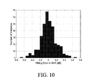
- FIG. 9 , FIG. 10 , FIG. 11 , FIG. 12 , FIG. 13 , and FIG. 14 illustrate fitting errors in Signal to Noise Ratio (SNR) for various 16 Quadrature Amplitude Modulation (16QAM) simulations regarding intra-channel Kerr noise;
- FIG. 15 , FIG. 16 , FIG. 17 , and FIG. 18 illustrate fitting errors in Signal to Noise Ratio (SNR) for various Quadrature Phase Shift Keying (QPSK) modulation simulations regarding total Kerr noise;
- SNR Signal to Noise Ratio
- QPSK Quadrature Phase Shift Keying
- FIG. 19 , FIG. 20 , FIG. 21 , and FIG. 22 illustrate fitting errors in Signal to Noise Ratio (SNR) for various 16 Quadrature Amplitude Modulation (16QAM) simulations regarding total Kerr noise;
- SNR Signal to Noise Ratio
- FIG. 23 illustrates an example neural network structure having two inputs, ten hidden nodes, and two outputs
- FIG. 24 illustrates another example neural network structure having four inputs, ten hidden nodes, and two outputs
- FIG. 25 illustrates error histograms for training samples for the example neural network structure illustrated in FIG. 23 ;
- FIG. 26 illustrates error histograms for test samples for the example neural network structure illustrated in FIG. 23 ;
- FIG. 27 illustrates error histograms for training samples for the example neural network structure illustrated in FIG. 24 ;
- FIG. 28 illustrates error histograms for test samples for the example neural network structure illustrated in FIG. 24 .
- Coherent detection gives access to optical fields after transmission, and provides a new path for link monitoring.
- the properties of Kerr nonlinear noise can be exploited to allow separation of linear noise, and intra-channel and inter-channel nonlinearities at fixed power provisioning.
- Challenges include proposing a method to exploit the properties of Kerr nonlinear noise based on the received signal, obtaining sufficient measurement accuracy over the wide variety of link applications services, and measuring nonlinear noise with ongoing traffic (in service).
- the Kerr effect is a third-order nonlinearity. Three fields (separated in time, or separated in frequency) interact to produce a fourth field.
- the Kerr effect is referred to as intra-channel Kerr nonlinear noise in cases where the three interacting fields are within a channel and the resulting fourth field is also within that same channel.
- the Kerr effect is referred to as inter-channel Kerr nonlinear noise in cases where the three interacting fields are between different channels (that is, one interacting field is from one channel and two interacting fields are from another channel, or each interacting field is from a different channel) and in cases where the three interacting fields are from one channel and the resulting fourth field is in a different channel.
- FIG. 1 illustrates a method 2 for characterizing a channel and optionally, for determining nonlinear noise.
- a coherent optical receiver isolates a noise component of a received signal.
- the noise component may be isolated from the received symbols and estimated transmitted symbols, or from the received symbols and training symbols.
- the coherent optical receiver determines C-matrices and doublet correlations that characterize how the Kerr effect is manifested in a channel.
- the C-matrices and doublet correlations which are described in more detail below, are determined using the nonlinear noise component that was isolated at 4 , and using received symbols or training symbols or estimated transmitted symbols.
- various techniques may be employed to reduce the complexity of determining the C-matrices.
- the coherent optical receiver uses the C-matrices and doublet correlations determined at 6 to calculate an estimated intra-channel noise-to-signal ratio (NSR) and to calculate a total nonlinear NSR.
- NSR noise-to-signal ratio
- the coherent optical receiver derives a linear NSR (also known as the optical NSR), for example, as the difference between the isolated noise and the total nonlinear NSR.
- A′ A+ ⁇ A (1)
- A [A X ,A Y ] T is the dual-polarization transmitted signal
- A′ [A X ′,A Y ′] T is the dual-polarization received signal
- ⁇ A [ ⁇ A X , ⁇ A Y ] T is the nonlinear noise component of the received signal.
- A, A′, and ⁇ A are functions of time t and distance z. Other noise, including linear noise and transceiver internal noise, is ignored in equation (1).
- ⁇ 2 is a second order dispersion coefficient
- ⁇ is an attenuation coefficient of the optical power
- equations (3) and (4) involve triplets of symbols: a symbol indexed by k+m, a symbol indexed by k+n, and a symbol indexed by k+m+n.
- the triplet is represented by the shorthand (k,m,n,m+n).
- the indices m and n can take on negative values, zero values and positive values.
- the sequence A X [ ⁇ 2], A X [ ⁇ 1], A X [0], A X [1], A X [2] represents five consecutively transmitted symbols for the X polarization.
- the contribution of the nonlinear intra-channel interaction between A X [ ⁇ 1], A X [1], and A X [2] to the intra-channel Kerr nonlinear noise for the X polarization, ⁇ A X [0], is given by C X [ ⁇ 1,2]A X [ ⁇ 1]A X [2]A X *[1].
- the C-matrices can be estimated by evaluating the cross-correlation between the intra-channel noise component and the fields of each (k,m,n,m+n) triplet, and taking into account the correlation between the triplets.
- Equation (5), (6), (11), (14), (15) and (20) E is an expectation, which is a weighted average.
- equations (3) through (22) the transmitted symbols can be replaced by the received symbols.
- C X [m, 0], C X [0, n], C XY [m, 0], C Y [m, 0], C Y [0, n], and C YX [m, 0] cannot be evaluated in this manner due to correlations between the various triplet terms.
- 2 is correlated with C X [2,0]A X [k]
- the coefficients C X [0,0], C Y [0,0], C XY [0,0], and C YX [0,0] cannot be evaluated.
- the total Kerr nonlinear noise component which includes both the intra-channel Kerr nonlinear noise component and the inter-channel Kerr nonlinear noise—can be approximated by:
- equations (25) and (26) one can focus on the intra-polarization correlation (the C-matrix C SPM ) or on the cross-polarization correlation (the C-matrix C XPM ) or on both correlations.
- the correlations of the doublet can be substituted by the expressions ⁇ A Y [k]/A X [k+n] and ⁇ A X [k]/A Y [k+n], respectively.
- These correlations can be used to estimate the total Kerr nonlinear noise-to-signal ratio. For example, assuming transmitted symbols are uncorrelated and normalized, the following is an example formulation for an approximation of the total Kerr nonlinear noise-to-signal ratio, denoted in this document as NL-NSR TOTAL :
- Equation (30) through (47) E is an expectation, which is a weighted average.
- the transmitted symbols can be replaced by the received symbols.
- FIG. 2 illustrates an example coherent optical receiver 10 .
- a polarizing beam splitter 12 is operative to split a received optical signal 14 into orthogonally-polarized components 16 , 18 .
- An optical hybrid 20 is operative to process the orthogonally-polarized components 16 , 18 with respect to a reference optical signal 22 produced by a laser 24 .
- Photodetectors 26 are operative to convert the output of the optical hybrid 20 to electrical signals corresponding to the in-phase (I) and quadrature (Q) components on both polarizations (say, an X-polarization and a Y-polarization).
- Amplifiers 28 are operative to amplify the electrical signals, and analog-to-digital converters (ADCs) 30 are operative to sample the amplified electrical signals.
- ADCs analog-to-digital converters
- An application specific integrated circuit (ASIC) 32 comprises components to process the output of the ADCs 30 to recover the data that was transmitted.
- the ASIC 32 comprises a digital signal processor (DSP) 34 .
- DSP digital signal processor
- the DSP 34 is operative to process the output of the ADCs 30 to perform dispersion compensation, polarization compensation, clock recovery, carrier recovery, symbol decoding, and so forth.
- a carrier recovery module 36 implemented by the DSP 34 is operative to track and remove the phase noise from both the transmit laser (not shown) and the laser 24 so as to produce digital representations 42 of analog received symbols (also referred to as “received waveforms”) for the X polarization and Y polarization.
- Each received symbol, and hence its digital representation, is composed of the true transmitted symbol and a noise component.
- the true transmitted symbol is the symbol modulated onto a polarized component of an optical carrier at a transmitter, the modulated optical carrier being sent over a channel to the coherent optical receiver 10 , where it is received as the received optical signal 14 .
- a decision block 38 implemented by the DSP 34 is operative to output decisions 44 regarding the received symbols for the X polarization and Y polarization.
- each decision 44 output by the decision block 38 is a set of bits representing an estimated transmitted symbol.
- the estimated transmitted symbol includes some error with respect to the true transmitted symbol. Over time, there might be more than 10% of the estimated transmitted symbols that are erroneous, that is, not identical to the true transmitted symbol.
- the decision block 38 implements a soft decision
- the most significant bit (MSB) of each soft decision output by the decision block 38 is part of the string of bits that is converted to the estimated transmitted symbol.
- the example coherent optical receiver 10 differs from conventional coherent optical receivers in that it comprises additional functionality to enable calculation of nonlinear noise-to-signal ratio.
- the remaining discussion of FIG. 2 describes this additional functionality as being implemented in the ASIC 32 .
- this additional functionality—or a portion thereof— is implemented in a low-speed processor 48 that is operatively coupled to the ASIC 32 .
- the low-speed processor 48 is illustrated as an optional component of the example coherent optical receiver 10 .
- the ASIC 32 may comprise a bit-to-symbol converter 50 , subtraction elements 52 , 54 , a delay element 56 , and a nonlinear noise-to-signal ratio (NSR) calculator 60 .
- the subtraction element 52 is for the X-polarization
- the subtraction element 54 is for the Y-polarization.
- the nonlinear NSR calculator 60 has access to calibration information 61 , as described in further detail below.
- the nonlinear NSR calculator 60 may also have access to training symbols 63 , as described in further detail below.
- the calibration information 60 and, if present, the training symbols 63 may be stored in a memory 59 .
- the nonlinear NSR calculator 60 may be implemented in software (also stored in the memory 59 ) or in firmware or in hardware or in any combination thereof.
- the bit-to-symbol converter 50 is operative to convert a set of bits into a digital representation 62 of an analog pristine symbol with no noise.
- the bit-to-symbol converter 50 receives, for each polarization, an input 64 that is the set of bits representing an estimated transmitted symbol (because the set of bits are a hard decision or the MSBs of a soft decision), and the digital representation 62 is of an analog pristine symbol identical to the estimated transmitted symbol with no noise.
- Each of the subtraction elements 52 , 54 is operative to subtract the digital representation 62 of the analog pristine symbol with no noise from a delayed version 66 of the digital representation 42 of the analog received symbol.
- the delay element 56 is operative to delay the digital representation 42 of the analog received symbol to yield the delayed version 66, so that the subtraction element 52 , 54 effects a comparison of the analog received symbol corresponding to a particular instant in time to an estimated transmitted symbol from the same instant in time.
- the output of the subtraction element 52 , 54 is a digital representation 68 of a noise component in the analog received symbol.
- R X [k] and R Y [k] are the digital representations of the received symbol indexed by k for the X-polarization and for the Y-polarization, respectively.
- a X [k] and A Y [k] are the digital representations of the estimated transmitted symbol indexed by k for the X-polarization and for the Y-polarization, respectively
- ⁇ A X [k] and ⁇ A X [k] are digital representations of the estimated noise component of the analog received symbol indexed by k for the X-polarization and for the Y-polarization, respectively.
- the nonlinear NSR calculator 60 is operative to perform nonlinear noise-to-signal ratio calculations based on its input.
- the nonlinear NSR calculator 60 receives as input, for the X-polarization and for the Y-polarization, the digital representations 68 of the noise component in the analog received symbol.
- the nonlinear NSR calculator 60 may also receive as input, for the X-polarization and for the Y-polarization, either the digital representation 58 of the analog pristine symbol (the estimated transmitted symbol) with no noise or the delayed version 66 of the digital representation 42 of the analog received symbol.
- the nonlinear NSR calculator 60 is operative to provide a measure or estimate of intra-channel Kerr nonlinear noise-to-signal ratio and a measure or estimate of total Kerr nonlinear noise-to-signal ratio.
- the intra-channel Kerr nonlinear noise-to-signal ratio is derived from measured triplet coefficients in the received noise.
- the total Kerr nonlinear noise-to-signal ratio is derived from doublet correlations in the received noise.
- the nonlinear NSR calculator 60 may evaluate the C-matrices C X and C XY according to equations (5) to (13), and the C-matrices C Y and C YX according to equations (14) to (22). In some implementations, the nonlinear NSR calculator 60 may calculate NL-NSR INTRA,X or Y according to equations (23) and (24).
- the nonlinear NSR calculator 60 may evaluate NL-NSR TOTAL according to equations (27) to (29).
- the noise component is isolated from the received symbols and the estimated transmitted symbols.
- the noise component is isolated from the received symbols and training symbols, where the training symbols 63 are substituted for the digital representation 62 of the analog pristine symbol with no noise.
- the previous discussion shows how doublet correlations are evaluated from the product or quotient of the isolated noise component and the field of a received symbol or of an estimated transmitted symbol.
- the training symbols 63 are substituted for the received symbols or for the estimated transmitted symbols in the calculations.
- nonlinear NSR calculator 60 may be employed by the nonlinear NSR calculator 60 , to increase the accuracy of the calculations, or to reduce the complexity of the calculations, or to reduce the number of calculations.
- Such techniques include exploitation of symmetry, limiting the range of values for the indices m and n over which the coefficients are evaluated, interpolation, truncation, and using machine learning techniques to extract information from fewer inputs.
- Reduced-complexity implementations for determining C-matrices are proposed. For example, inter-channel noise may be ignored. In an alternative example, when considering inter-channel noise, only nearest neighbor channels may be included, and other channels may be ignored.
- the extent of the Kerr effect is related to the memory of the channel, and the values for the indices m and n that are considered in the summation relate to the memory accounted for in the calculations.
- the indices m and n in equations (5) to (22) can take on negative values, zero values and positive values. Symmetry may be exploited, to reduce the number of coefficients that are evaluated, or to increase accuracy by averaging over symmetric coefficients, or both.
- the C-matrices C X , C Y , C XY , and C YX could be calculated only for positive values of the indices m and n, relying on symmetry of the quadrants to determine the coefficients for the other quadrants.
- averaging could be evaluated as follows, where C could be any one of the C-matrices C X , C Y , C XY , and C YX :
- the extent of the Kerr effect is related to the memory of the channel.
- the memory of the channel is determined by factors such as dispersion, link length, and signal bandwidth.
- the symbols and coefficients are indexed by absolute time units, then as the baud increases the number of symbols to be included in the summations has to increase, because the number of symbols in a particular time span has increased.
- the spectral extent of the channel increases, and through dispersion, the amount of spread in time increases. So the memory of the channel, when indexed or measured in absolute time units, goes roughly as the baud squared.
- m and n values may be sufficient to consider m and n values in the range of ⁇ 10 through +10. In other cases, it may be prudent to consider m and n values in the range of ⁇ 100 through +100, or in the range of ⁇ 200 through +200.
- FIG. 3 illustrates a Cartesian graph with axes labeled m and n.
- An interior area 70 indicates the values of m and n for which the C-matrix coefficients are of interest. That is, one can ignore C-matrix coefficients C[m,n] for values of m,n that are not within the interior area 70 , but are within the remaining areas 72 .
- a channel employs frequency division multiplexing (FDM)
- FDM frequency division multiplexing
- C-matrix coefficients are required for each the C-matrices C X , C Y , C XY , and C YX to obtain a relatively accurate estimation of NL-NSR INTRA,X or Y .
- computation of so many C-matrix coefficients might take too long, based on hardware that is currently available.
- NL-NSR INTRA,X or Y can be calculated based on the power of the coefficients in the C-matrices. For each index m we can define
- the quantity P X [m] (equations (51) and (52)) or the quantity P Y [m] (equations (53) and (54)) may be evaluated for the index m belonging to the set ⁇ 0, 1, 2, 3, 4, 6, 9, 19, 29, 49, 69, 99, 129, 159, 199 ⁇ .
- the values of the C-matrix coefficients are expected to be very small when the index m is large. Therefore more precision is used for small values of the index m than for large values of the index m.
- the values of the quantity P X [m] or the quantity P Y [m] for other values of the index m ⁇ [0,199] may be obtained by simple linear interpolation. This example involves approximately four thousand C-matrix coefficients for each of the C-matrices C X , C Y , C XY , and C YX , compared to the ten thousand C-matrix coefficients mentioned above.
- the errors may be due to one or more of the following factors: the model being an approximation of the actual nonlinearity, the use of estimated transmitted symbols rather than true transmitted symbols to determine the C-matrices, the use of techniques to reduce computation complexity, the use of interpolation, and simplifications in the equations (for example, focusing on the cross-polarization correlation (the C-matrix C XPM ) in equations (25) and (26)). Calibration techniques are employed by the nonlinear NSR calculator 60 to reduce the errors and improve accuracy.
- FIG. 4 illustrates a method 80 for developing and using calibration information.
- Calibration information 61 used by the nonlinear NSR calculator 60 is an example of calibration to be developed and used according to the method 80 .
- An application is defined as a particular configuration of an optical communication system, characterized by fiber type, distance between transmitter and receiver, line chromatic dispersion compensation (CDC) ratio, number of wavelength-division multiplexing (WDM) channels, and the launch power of the signal.
- fiber type characterized by fiber type, distance between transmitter and receiver, line chromatic dispersion compensation (CDC) ratio, number of wavelength-division multiplexing (WDM) channels, and the launch power of the signal.
- CDC line chromatic dispersion compensation
- WDM wavelength-division multiplexing
- SSFM Split-step Fourier method
- Each simulation of a particular application involves known transmitted symbols, known nonlinear inter-channel Kerr noise and known nonlinear intra-channel Kerr noise.
- a coherent optical receiver that implements the method 2 described with respect to FIG. 1 and FIG. 2 is simulated.
- the simulated coherent optical receiver isolates a noise component of a received signal or symbol, calculates C-matrices using the isolated noise component and either an estimated transmitted symbol or the known transmitted symbol, and, optionally, calculates a nonlinear contribution to the total NSR.
- the calculated nonlinear contribution to the total NSR can be compared to the known noise used in the simulation.
- the calibration information 61 is based on the series of relationships.
- the relationships are polynomials, developing the relationships involves determining coefficients of the polynomials using known fitting techniques, and the calibration information 61 includes the polynomials, their determined coefficients, and one or more attributes of the link.
- the relationships are developed using neural networks, and the calibration information 61 includes a trained neural network and optionally one or more attributes of the link.
- the nonlinear NSR calculator 60 uses the calibration information 61 based on the series of relationships developed at 84 to calibrate or correct the calculation of the C-matrices (or to calibrate or correct the calculation of the nonlinear contribution to total NSR).
- NL-NSR INTRA,X or Y ′ NL-NSR INTRA,X or Y ⁇ f (CD net ,D avg ,SER,NL-NSR INTRA,X or Y ) (59) here NL-NSR INTRA,X or Y is the calibrated estimation, f( ⁇ ) is the calibration relationship for application-dependent systematic errors as well as symbol error rate (SER)-induced errors, CD net is the net chromatic dispersion, and D avg is the average dispersion.
- SER symbol error rate
- Fitting results for WDM channels 1 , 3 , 5 and 7 for 16QAM are illustrated in FIG. 19 , FIG. 20 , FIG. 21 and FIG. 22 , respectively.
- the coefficients obtained are summarized in Table 3.
- a neural network implementation is used to improve the accuracy of the determination of intra-channel Kerr nonlinear noise-to-signal ratio and of total Kerr nonlinear noise-to-signal ratio by training the neural network with data sets of known inputs and known outputs (the outputs being related to the intra-channel Kerr nonlinearity and to the total Kerr nonlinearity), and then applying the trained neural network to actual inputs.
- neural network structures having two outputs may be used, with one output related to the intra-channel Kerr nonlinearity (for example, NL-NSR INTRA,X or Y ) and the other output related to the total Kerr nonlinearity (for example, NL-NSR TOTAL ).
- the inputs may include the coefficients of the C-matrices C X , C Y , C XY , and C YX , and doublet correlations (for example, any one or any combination of the doublet correlations of equations (30) through (47)).
- the inputs may also include the results obtained by pre-processing the C-matrices and the one or more doublet correlations.
- the inputs may also include one or more attributes of the link, for example, one or more of net chromatic dispersion, link length, fiber type, span length, WDM configuration, and the like.
- FIG. 23 illustrates an example neural network structure having two inputs, a single hidden layer with ten nodes, and two outputs.
- FIG. 24 illustrates another example neural network structure having four inputs, a single hidden layer with ten nodes, and two outputs.
- the two outputs are intra-channel Kerr nonlinearity and total Kerr nonlinearity
- two of the inputs are C-matrix measurements and doublet correlation.
- the additional two inputs are net chromatic dispersion and link length.
- Error histograms for training samples and test samples are illustrated in FIG. 25 and FIG. 26 , respectively, for the example neural network structure having two inputs illustrated in FIG. 23 .
- the training mean square error (MSE) was 0.84 Db and the test MSE was 0.94 dB.
- Error histograms for training samples and test samples are illustrated in FIG. 27 and FIG. 28 , respectively, for the example neural network structure having four inputs illustrated in FIG. 24 .
- the training mean square error (MSE) was 0.075 Db and the test MSE was 0.079 dB.
Landscapes
- Engineering & Computer Science (AREA)
- Physics & Mathematics (AREA)
- Theoretical Computer Science (AREA)
- Computer Networks & Wireless Communication (AREA)
- Signal Processing (AREA)
- Electromagnetism (AREA)
- Software Systems (AREA)
- Artificial Intelligence (AREA)
- Data Mining & Analysis (AREA)
- Evolutionary Computation (AREA)
- Mathematical Physics (AREA)
- Computing Systems (AREA)
- General Engineering & Computer Science (AREA)
- General Physics & Mathematics (AREA)
- Biomedical Technology (AREA)
- Health & Medical Sciences (AREA)
- Life Sciences & Earth Sciences (AREA)
- Biophysics (AREA)
- Computational Linguistics (AREA)
- General Health & Medical Sciences (AREA)
- Molecular Biology (AREA)
- Medical Informatics (AREA)
- Computer Vision & Pattern Recognition (AREA)
- Optical Communication System (AREA)
Abstract
Description
A′=A+ΔA (1)
where A=[AX,AY]T is the dual-polarization transmitted signal, A′=[AX′,AY′]T is the dual-polarization received signal, and ΔA=[ΔAX, ΔAY]T is the nonlinear noise component of the received signal. A, A′, and ΔA are functions of time t and distance z. Other noise, including linear noise and transceiver internal noise, is ignored in equation (1).
where β2 is a second order dispersion coefficient, and α is an attenuation coefficient of the optical power.
where ΔAX[k] is the nonlinear noise component indexed by k for the X-polarization, ΔAY[k] is the nonlinear noise component indexed by k for the Y-polarization, AX[k] is the transmitted symbol indexed by k for the X-polarization, AY[k] is the transmitted symbol indexed by k for the Y-polarization, and the asterisk (*) denotes conjugation. AX or Y[k] is a sampled version of AX or Y in equations (1) and (2), and ΔAX or Y[k] is a sampled version of ΔAX or Y in equations (1) and (2).
C′ X [m,n]=E[ΔA X [k]·A X *[k+m]·A X *[k+n]·A X [k+m+n]] (5)
C′ XY [m,n]=E[ΔA X [k]·A X *[k+m]·A Y *[k+n]·A Y [k+m+n]] (6)
Q X [k,m,n]=A X [k+m]·A X [k+n]·A X *[k+m+n] (7)
Q XY [k,m,n]=A X [k+m]·A Y [k+n]·A Y *[k+m+n] (8)
{right arrow over (C)} X′=vec(C X ′[m,n],C XY ′[m,n]) (9)
{right arrow over (Q)} X=vec(Q X [k,m,n],Q XY [k,m,n]) (10)
R X =E[{right arrow over (Q)} X {right arrow over (Q)} X H] (11)
{right arrow over (C)} X ={right arrow over (C)} X′inv(R X) (12)
(C X [m,n],C XY [m,n])=vec−1({right arrow over (C)} X) (13)
where vec(⋅) is a function that converts the matrices to a single vector with a certain order of all elements, vec−1(⋅) is the inverse operation of vec(⋅), and inv(⋅) is inverse of a matrix.
C′ Y [m,n]=E[ΔA Y [k]·A Y *[k+m]·A Y *[k+n]·A Y [k+m+n]] (14)
C′ YX [m,n]=E[ΔA Y [k]·A Y *[k+m]·A X *[k+n]·A X [k+m+n]] (15)
Q Y [k,m,n]=A Y [k+m]·A Y [k+n]·A Y *[k+m+n] (16)
Q YX [k,m,n]=A Y [k+m]·A X [k+n]·A X *[k+m+n] (17)
{right arrow over (C)} Y′=vec(C Y ′[m,n],C YX ′[m,n]) (18)
{right arrow over (Q)} Y=vec(Q Y [k,m,n],Q YX [k,m,n]) (19)
R Y =E[{right arrow over (Q)} Y {right arrow over (Q)} Y H] (20)
{right arrow over (C)} Y ={right arrow over (C)} Y′inv(R Y) (21)
(C Y [m,n],C YX [m,n])=vec−1({right arrow over (C)} Y) (22)
where vec(⋅) is a function that convert the matrices to a single vector with a certain order of all elements, vec−1(⋅) is the inverse operation of vec(⋅), and inv(⋅) is inverse of a matrix.
NL-NSRINTRA,X ≈E[{right arrow over (C)} X H {right arrow over (Q)} X {right arrow over (Q)} X H {right arrow over (C)} X ]={right arrow over (C)} X H E[{right arrow over (Q)} X {right arrow over (Q)} X H ]{right arrow over (C)} X ={right arrow over (C)} X H R X {right arrow over (C)} X (23)
NL-NSRINTRA,Y ≈E[{right arrow over (C)} Y H {right arrow over (Q)} Y {right arrow over (Q)} Y H {right arrow over (C)} Y ]={right arrow over (C)} Y H E[{right arrow over (Q)} Y {right arrow over (Q)} Y H ]{right arrow over (C)} Y ={right arrow over (C)} Y H R Y {right arrow over (C)} Y (24)
In equations (23) and (24), E is an expectation, which is a weighted average.
where ΔAX[k] is the total nonlinear noise component indexed by k for the X-polarization in the channel, ΔAY[k] is the total nonlinear noise component indexed by k for the Y-polarization in the channel, AX[k] is the transmitted symbol indexed by k for the X-polarization in the channel, AY[k] is the transmitted symbol indexed by k for the Y-polarization in the channel, BX[k] is the transmitted symbol indexed by k for the X-polarization in a different channel, BY[k] is the transmitted symbol indexed by k for the Y-polarization in the different channel, and the asterisk (*) denotes conjugation.
-
- ΣmCSPM[m, n](AX[k+m]AX*[k+m+n]+AY[k+m]AY*[k+m+n]) in equation (25);
- ΣmCXPM[m, n](2BX[k+m]BX*[k+m+n]+BY[k+m]BY*[k+m+n]) in equation (25);
- ΣmCXPM[m, n]BX[k+m]BY*[k+m+n] in equation (25); and
- ΣmCSPM[m, n](AY[k+m]AY*[k+m+n]+AX[k+m]AX*[k+m+n]) in equation (26);
- ΣmCXPM[m, n](2BY[k+m]BY*[k+m+n]+BX[k+m]BX*[k+m+n]) in equation (26);
- ΣmCXPM[m, n]BY[k+m]BX*[k+m+n] in equation (26).
where N denotes the symbol delay in the estimation, which is related to estimation accuracy and time. For a link with a long memory, that is, with high net chromatic dispersion, a large N should be used in principle. In equations (28) and (29), E is an expectation, which is a weighted average.
| TABLE 1 |
| Applications for systematic error study |
| Line | Power | Power | |||
| Fiber | CDC | WDM | (dBm) | (dBm) | |
| Type | Distance (km) | ratio | CHs | 0% CDC | 90% CDC |
| NDSF | 320, 640, 1200, | 0%, | 1, 3, 5, 7 | −1.5, 0.5, | −4, −2, 0 |
| 2000, 3200 | 90% | 2.5 | |||
| TWC | 320, 640, 1200, | 0%, | 1, 3, 5, 7 | −4.5, −2.5, | −6, −4, −2 |
| 2000, 3200 | 90% | −0.5 | |||
| ELEAF | 320, 640, 1200, | 0%, | 1, 3, 5, 7 | −3, −1, 1 | −5, −3, −1 |
| 2000, 3200 | 90% | ||||
| NDSF & | 320, 640, 1200, | 0%, | 1, 3, 5, 7 | −3, −1, 1 | −5, −3, −1 |
| TWC | 2000, 3200 | 90% | |||
| NDSF & | 320, 640, 1200, | 0%, | 1, 3, 5, 7 | −2.5, −0.5, | −4.5, −2.5, |
| ELEAF | 2000, 3200 | 90% | 1.5 | −0.5 | |
| ELEAF & | 320, 640, 1200, | 0%, | 1, 3, 5, 7 | −4, −2, 0 | −5.5, −3.5, |
| TWC | 2000, 3200 | 90% | −1.5 | ||
ε=c 0 +c 1 ·x+c 2 ·x 2 (57)
where ε is the offset in dB, x=log10 (net chromatic dispersion in ps/nm), and the coefficients obtained were c0=7.029, c1=−3.343, and c2=0.472 with a root mean square error (RMSE) of 0.3008 dB. The fitting error in SNR (dB) is illustrated in
ε=c 0 +c 1 ·x+c 2 ·y+c 3 ·x 2 +c 4 ·xy=c 5 ·y 2 (58)
where ε is the offset in dB, x=log10 (net chromatic dispersion in ps/nm), y=[net chromatic dispersion in ps/nm]/[link length in km], and the coefficients obtained were c0=6.438, c1=−2.695, c2=0.08515, c3=0.294, c4=0.03263, and c5=−0.009783 with a root mean square error (RMSE) of 0.2255 dB. The fitting error in SNR (dB) is illustrated in
NL-NSRINTRA,X or Y′=NL-NSRINTRA,X or Y ·f(CDnet ,D avg,SER,NL-NSRINTRA,X or Y) (59)
here NL-NSRINTRA,X or Y is the calibrated estimation, f(⋅) is the calibration relationship for application-dependent systematic errors as well as symbol error rate (SER)-induced errors, CDnet is the net chromatic dispersion, and Davg is the average dispersion.
ε=c 0 +c 1 ·x+c 2 ·y+c 3 ·x 2 +c 4 ·xy+c 5 ·y 2 (60)
where ε is the offset in dB, x=log10 (net chromatic dispersion in ps/nm), and y=[net chromatic dispersion in ps/nm]/[link length in km].
| TABLE 2 |
| Fitting results with net chromatic dispersion and |
| link length for different WDM cases for QPSK |
| RMS | |||
| Fitting coefficients | (dB) | | |
| WDM ch | |||
| 1 |  |
0.1510 | 0.9613 |
| 0.2055, 0.0464, −0.0114] | |||
| |
|
0.2504 | 0.8908 |
| 0.6243, 0.0540, −0.0223] | |||
| |
|
0.2618 | 0.8770 |
| 0.6915, 0.0399, −0.0226] | |||
| |
|
0.2788 | 0.8229 |
| 0.7590, 0.0611, −0.0218] | |||
| TABLE 3 |
| Fitting results with net chromatic dispersion and |
| link length for different WDM cases for QPSK |
| RMS | |||
| Fitting coefficients | (dB) | | |
| WDM ch | |||
| 1 | |
0.1591 | 0.9585 |
| 0.8156, 0.0000, −0.0075] | |||
| |
|
0.2375 | 0.9120 |
| 0.7388, 0.0413, −0.0203] | |||
| |
|
0.2515 | 0.9054 |
| 0.8064, 0.0461, −0.0233] | |||
| |
|
0.2716 | 0.8750 |
| 0.8062, 0.0234, −0.0211] | |||
Claims (20)
Priority Applications (1)
| Application Number | Priority Date | Filing Date | Title |
|---|---|---|---|
| US15/461,718 US10090920B1 (en) | 2017-03-17 | 2017-03-17 | Fiber kerr nonlinear noise estimation |
Applications Claiming Priority (1)
| Application Number | Priority Date | Filing Date | Title |
|---|---|---|---|
| US15/461,718 US10090920B1 (en) | 2017-03-17 | 2017-03-17 | Fiber kerr nonlinear noise estimation |
Publications (2)
| Publication Number | Publication Date |
|---|---|
| US20180269968A1 US20180269968A1 (en) | 2018-09-20 |
| US10090920B1 true US10090920B1 (en) | 2018-10-02 |
Family
ID=63519814
Family Applications (1)
| Application Number | Title | Priority Date | Filing Date |
|---|---|---|---|
| US15/461,718 Active US10090920B1 (en) | 2017-03-17 | 2017-03-17 | Fiber kerr nonlinear noise estimation |
Country Status (1)
| Country | Link |
|---|---|
| US (1) | US10090920B1 (en) |
Cited By (4)
| Publication number | Priority date | Publication date | Assignee | Title |
|---|---|---|---|---|
| WO2019123264A1 (en) | 2017-12-21 | 2019-06-27 | Ciena Corporation | Fiber parameter identification |
| US11507476B2 (en) * | 2020-01-09 | 2022-11-22 | Fujitsu Limited | Noise estimation method, non-transitory computer-readable storage medium, and noise estimation apparatus |
| US11799560B2 (en) | 2019-10-31 | 2023-10-24 | Ciena Corporation | Asymmetric direct detection of optical signals |
| US11821807B2 (en) | 2021-01-25 | 2023-11-21 | Ciena Corporation | Estimating nonlinear phase shift in a multi-span fiber-optic link using a coherent receiver |
Families Citing this family (11)
| Publication number | Priority date | Publication date | Assignee | Title |
|---|---|---|---|---|
| CN110971295B (en) * | 2018-09-28 | 2023-01-17 | 富士通株式会社 | Fiber optic nonlinear noise monitoring device and optical receiver |
| CN109379132B (en) * | 2018-12-05 | 2020-06-05 | 北京理工大学 | Device and method for estimating optical fiber dispersion by low-speed coherent detection and neural network |
| CN110166119B (en) * | 2019-05-29 | 2020-06-16 | 北京理工大学 | Coherent optical communication transmitter monitoring method based on deep neural network |
| CN110324091B (en) * | 2019-06-17 | 2022-05-03 | 电子科技大学 | A Nonlinear Equalizer Based on Function Chain Neural Network |
| US11309960B2 (en) * | 2019-06-27 | 2022-04-19 | Viavi Solutions Inc. | Measuring linear and non-linear transmission perturbations in optical transmission systems |
| CN110932809B (en) * | 2019-11-20 | 2020-10-16 | 北京邮电大学 | Fiber channel model simulation method, device, electronic equipment and storage medium |
| US11576065B2 (en) * | 2020-06-02 | 2023-02-07 | Intelligent Fusion Technology, Inc. | Method, device, and storage medium for communication waveform performance predication |
| CN115694710B (en) * | 2022-10-12 | 2024-05-14 | 香港理工大学深圳研究院 | Dual-polarization combined signal noise processing method and noise processing device |
| US12476712B2 (en) * | 2023-09-08 | 2025-11-18 | Huawei Technologies Co., Ltd. | Method and device for monitoring generalized optical signal-to-noise ratio, coherent receiver and network apparatus |
| CN118784080B (en) * | 2024-07-10 | 2025-11-07 | 华中科技大学 | Fiber nonlinear equalization method and system based on bit-by-bit estimation neural network |
| CN119449177B (en) * | 2024-10-16 | 2026-01-06 | 鹏城实验室 | Methods, apparatus, equipment, and storage media for measuring the Kerr effect nonlinear coefficient of hollow-core optical fiber. |
Citations (13)
| Publication number | Priority date | Publication date | Assignee | Title |
|---|---|---|---|---|
| US20040184398A1 (en) * | 2003-03-20 | 2004-09-23 | Walton Jay Rod | Transmission mode selection for data transmission in a multi-channel communication system |
| US20040208271A1 (en) * | 2003-01-17 | 2004-10-21 | Gruenberg Elliot L. | Coding system for minimizing digital data bandwidth |
| US7376358B2 (en) * | 2002-10-03 | 2008-05-20 | Nortel Networks Limited | Location specific optical monitoring |
| US7756421B2 (en) * | 2002-10-03 | 2010-07-13 | Ciena Corporation | Electrical domain compensation of non-linear effects in an optical communications system |
| US20100183060A1 (en) * | 2009-01-19 | 2010-07-22 | Electronics And Telecommunications Research Institute | Method and apparatus of frequency offset-free frame synchronization for high order qam signals in modem apparatus |
| US20110085797A1 (en) * | 2009-10-09 | 2011-04-14 | Nec Laboratories America, Inc. | Ultra wide-range frequency offset estimation for digital coherent optical receivers |
| US20150071174A1 (en) * | 2011-01-20 | 2015-03-12 | Telefonaktiebolaget Lm Ericsson (Publ) | Backhaul signal compression through spatial-temporal linear prediction |
| US20150171972A1 (en) * | 2012-08-28 | 2015-06-18 | Huawei Technologies Co., Ltd. | Optical Receiver |
| US20160233963A1 (en) * | 2013-09-09 | 2016-08-11 | Ciena Corporation | Reduced complexity nonlinear compensation |
| US20160323091A1 (en) * | 2013-11-15 | 2016-11-03 | National Institute Of Advanced Industrial Science And Technology | Received Signal Processing Device, Communication System, and Received Signal Processing Method |
| US20170041078A1 (en) * | 2014-04-08 | 2017-02-09 | Aston University | Method of non-linearity compensation in optical fibre communications |
| US9768880B2 (en) * | 2015-05-20 | 2017-09-19 | Ciena Corporation | Method and system for nonlinear interference mitigation |
| US9768875B2 (en) * | 2012-11-12 | 2017-09-19 | Ciena Corporation | Optical modulation schemes having reduced nonlinear optical transmission impairments |
-
2017
- 2017-03-17 US US15/461,718 patent/US10090920B1/en active Active
Patent Citations (13)
| Publication number | Priority date | Publication date | Assignee | Title |
|---|---|---|---|---|
| US7376358B2 (en) * | 2002-10-03 | 2008-05-20 | Nortel Networks Limited | Location specific optical monitoring |
| US7756421B2 (en) * | 2002-10-03 | 2010-07-13 | Ciena Corporation | Electrical domain compensation of non-linear effects in an optical communications system |
| US20040208271A1 (en) * | 2003-01-17 | 2004-10-21 | Gruenberg Elliot L. | Coding system for minimizing digital data bandwidth |
| US20040184398A1 (en) * | 2003-03-20 | 2004-09-23 | Walton Jay Rod | Transmission mode selection for data transmission in a multi-channel communication system |
| US20100183060A1 (en) * | 2009-01-19 | 2010-07-22 | Electronics And Telecommunications Research Institute | Method and apparatus of frequency offset-free frame synchronization for high order qam signals in modem apparatus |
| US20110085797A1 (en) * | 2009-10-09 | 2011-04-14 | Nec Laboratories America, Inc. | Ultra wide-range frequency offset estimation for digital coherent optical receivers |
| US20150071174A1 (en) * | 2011-01-20 | 2015-03-12 | Telefonaktiebolaget Lm Ericsson (Publ) | Backhaul signal compression through spatial-temporal linear prediction |
| US20150171972A1 (en) * | 2012-08-28 | 2015-06-18 | Huawei Technologies Co., Ltd. | Optical Receiver |
| US9768875B2 (en) * | 2012-11-12 | 2017-09-19 | Ciena Corporation | Optical modulation schemes having reduced nonlinear optical transmission impairments |
| US20160233963A1 (en) * | 2013-09-09 | 2016-08-11 | Ciena Corporation | Reduced complexity nonlinear compensation |
| US20160323091A1 (en) * | 2013-11-15 | 2016-11-03 | National Institute Of Advanced Industrial Science And Technology | Received Signal Processing Device, Communication System, and Received Signal Processing Method |
| US20170041078A1 (en) * | 2014-04-08 | 2017-02-09 | Aston University | Method of non-linearity compensation in optical fibre communications |
| US9768880B2 (en) * | 2015-05-20 | 2017-09-19 | Ciena Corporation | Method and system for nonlinear interference mitigation |
Non-Patent Citations (2)
| Title |
|---|
| Choi, et al., "Nonlinearity-tolerant OSNR estimation technique for coherent optical systems," 2015 Optical Fiber communications Conference and Exhibition (OFC), Los Angeles, CA, 2015, Paper W4D.2. |
| Dong, et al., "OSNR monitoring for QPSK and 16-QAM systems in presence of fiber nonlinearities for digital coherent receivers," Opt. Express 20, 19520-19534 (2012). |
Cited By (5)
| Publication number | Priority date | Publication date | Assignee | Title |
|---|---|---|---|---|
| WO2019123264A1 (en) | 2017-12-21 | 2019-06-27 | Ciena Corporation | Fiber parameter identification |
| US11799560B2 (en) | 2019-10-31 | 2023-10-24 | Ciena Corporation | Asymmetric direct detection of optical signals |
| US11507476B2 (en) * | 2020-01-09 | 2022-11-22 | Fujitsu Limited | Noise estimation method, non-transitory computer-readable storage medium, and noise estimation apparatus |
| US11821807B2 (en) | 2021-01-25 | 2023-11-21 | Ciena Corporation | Estimating nonlinear phase shift in a multi-span fiber-optic link using a coherent receiver |
| US11971323B2 (en) | 2021-01-25 | 2024-04-30 | Ciena Corporation | Estimating nonlinear phase shift in a multi-span fiber-optic link using a coherent receiver |
Also Published As
| Publication number | Publication date |
|---|---|
| US20180269968A1 (en) | 2018-09-20 |
Similar Documents
| Publication | Publication Date | Title |
|---|---|---|
| US10090920B1 (en) | Fiber kerr nonlinear noise estimation | |
| US10236982B1 (en) | Fiber parameter identification | |
| US9319137B2 (en) | Methods and systems for reduced complexity nonlinear compensation | |
| JP5147582B2 (en) | Reception device, compensation arithmetic circuit, and reception method | |
| US8935115B2 (en) | Method and apparatus for compensating nonlinear damage | |
| CN107078982B (en) | Dispersion estimation for digital coherent optical receiver | |
| US11575556B2 (en) | Estimation of communication system impairments using spectrally selective signal perturbations | |
| US12500672B2 (en) | Optical receiving apparatus and frequency offset compensation method | |
| WO2016173324A1 (en) | Optical signal to noise ratio monitoring method and device | |
| CN104601239A (en) | Optical fiber adaptive nonlinear compensation scheme based on intensity noise variance and low-pass filter | |
| JP2019514280A (en) | Method of decoding symbols transmitted via an optical communication channel, non-transitory computer readable storage medium and system | |
| Cantono et al. | Observing the interaction of PMD with generation of NLI in uncompensated amplified optical links | |
| CN106464373B (en) | Apparatus for determining signal distortion of an optical signal | |
| Al-Nahhal et al. | Joint estimation of linear and nonlinear coherent optical fiber signal-to-noise ratio | |
| Salehiomran et al. | Linear and nonlinear noise monitoring in coherent systems using fast BER measurement and neural networks | |
| US12425104B2 (en) | Receiver-based fiber-optic link monitor | |
| Lavigne et al. | System design tool for high bit rate terrestrial transmission systems with coherent detection | |
| Vaquero-Caballero et al. | Transceiver noise characterization based on perturbations | |
| Sombrin | On the formal identity of EVM and NPR measurement methods: Conditions for identity of error vector magnitude and noise power ratio | |
| Al-Nahhal et al. | Learned signal-to-noise ratio estimation in optical fiber communication links | |
| Kashi et al. | Artificial neural networks for fiber nonlinear noise estimation | |
| Hu et al. | A novel cost-effective and distributed in-band OSNR monitoring method using Gaussian process regression | |
| Wang et al. | OSNR monitoring technique based on multi-order statistical moment method and correlation function for PM-16QAM in presence of fiber nonlinearities | |
| Layec et al. | Generalized maximum likelihood for cross-polarization modulation effects compensation | |
| Purkayastha et al. | Accuracy enhancement of an optical network digital twin based on open-source field data |
Legal Events
| Date | Code | Title | Description |
|---|---|---|---|
| AS | Assignment |
Owner name: CIENA CORPORATION, MARYLAND Free format text: ASSIGNMENT OF ASSIGNORS INTEREST;ASSIGNORS:ZHUGE, QUNBI;O'SULLIVAN, MAURICE;REIMER, MICHAEL ANDREW;REEL/FRAME:041754/0229 Effective date: 20170317 |
|
| STCF | Information on status: patent grant |
Free format text: PATENTED CASE |
|
| CC | Certificate of correction | ||
| MAFP | Maintenance fee payment |
Free format text: PAYMENT OF MAINTENANCE FEE, 4TH YEAR, LARGE ENTITY (ORIGINAL EVENT CODE: M1551); ENTITY STATUS OF PATENT OWNER: LARGE ENTITY Year of fee payment: 4 |
|
| MAFP | Maintenance fee payment |
Free format text: PAYMENT OF MAINTENANCE FEE, 8TH YEAR, LARGE ENTITY (ORIGINAL EVENT CODE: M1552); ENTITY STATUS OF PATENT OWNER: LARGE ENTITY Year of fee payment: 8 |