US10090608B2 - Electrical connection system having a terminal with contact ridges - Google Patents
Electrical connection system having a terminal with contact ridges Download PDFInfo
- Publication number
- US10090608B2 US10090608B2 US15/280,522 US201615280522A US10090608B2 US 10090608 B2 US10090608 B2 US 10090608B2 US 201615280522 A US201615280522 A US 201615280522A US 10090608 B2 US10090608 B2 US 10090608B2
- Authority
- US
- United States
- Prior art keywords
- terminal
- resilient contact
- contact
- female
- connection system
- Prior art date
- Legal status (The legal status is an assumption and is not a legal conclusion. Google has not performed a legal analysis and makes no representation as to the accuracy of the status listed.)
- Active, expires
Links
Images


Classifications
-
- H—ELECTRICITY
- H01—ELECTRIC ELEMENTS
- H01R—ELECTRICALLY-CONDUCTIVE CONNECTIONS; STRUCTURAL ASSOCIATIONS OF A PLURALITY OF MUTUALLY-INSULATED ELECTRICAL CONNECTING ELEMENTS; COUPLING DEVICES; CURRENT COLLECTORS
- H01R4/00—Electrically-conductive connections between two or more conductive members in direct contact, i.e. touching one another; Means for effecting or maintaining such contact; Electrically-conductive connections having two or more spaced connecting locations for conductors and using contact members penetrating insulation
- H01R4/26—Connections in which at least one of the connecting parts has projections which bite into or engage the other connecting part in order to improve the contact
-
- H—ELECTRICITY
- H01—ELECTRIC ELEMENTS
- H01R—ELECTRICALLY-CONDUCTIVE CONNECTIONS; STRUCTURAL ASSOCIATIONS OF A PLURALITY OF MUTUALLY-INSULATED ELECTRICAL CONNECTING ELEMENTS; COUPLING DEVICES; CURRENT COLLECTORS
- H01R13/00—Details of coupling devices of the kinds covered by groups H01R12/70 or H01R24/00 - H01R33/00
- H01R13/02—Contact members
- H01R13/15—Pins, blades or sockets having separate spring member for producing or increasing contact pressure
-
- H—ELECTRICITY
- H01—ELECTRIC ELEMENTS
- H01R—ELECTRICALLY-CONDUCTIVE CONNECTIONS; STRUCTURAL ASSOCIATIONS OF A PLURALITY OF MUTUALLY-INSULATED ELECTRICAL CONNECTING ELEMENTS; COUPLING DEVICES; CURRENT COLLECTORS
- H01R13/00—Details of coupling devices of the kinds covered by groups H01R12/70 or H01R24/00 - H01R33/00
- H01R13/02—Contact members
- H01R13/22—Contacts for co-operating by abutting
- H01R13/24—Contacts for co-operating by abutting resilient; resiliently-mounted
- H01R13/2442—Contacts for co-operating by abutting resilient; resiliently-mounted with a single cantilevered beam
-
- H—ELECTRICITY
- H01—ELECTRIC ELEMENTS
- H01R—ELECTRICALLY-CONDUCTIVE CONNECTIONS; STRUCTURAL ASSOCIATIONS OF A PLURALITY OF MUTUALLY-INSULATED ELECTRICAL CONNECTING ELEMENTS; COUPLING DEVICES; CURRENT COLLECTORS
- H01R13/00—Details of coupling devices of the kinds covered by groups H01R12/70 or H01R24/00 - H01R33/00
- H01R13/02—Contact members
- H01R13/04—Pins or blades for co-operation with sockets
-
- H—ELECTRICITY
- H01—ELECTRIC ELEMENTS
- H01R—ELECTRICALLY-CONDUCTIVE CONNECTIONS; STRUCTURAL ASSOCIATIONS OF A PLURALITY OF MUTUALLY-INSULATED ELECTRICAL CONNECTING ELEMENTS; COUPLING DEVICES; CURRENT COLLECTORS
- H01R13/00—Details of coupling devices of the kinds covered by groups H01R12/70 or H01R24/00 - H01R33/00
- H01R13/02—Contact members
- H01R13/10—Sockets for co-operation with pins or blades
- H01R13/11—Resilient sockets
- H01R13/113—Resilient sockets co-operating with pins or blades having a rectangular transverse section
-
- H—ELECTRICITY
- H01—ELECTRIC ELEMENTS
- H01R—ELECTRICALLY-CONDUCTIVE CONNECTIONS; STRUCTURAL ASSOCIATIONS OF A PLURALITY OF MUTUALLY-INSULATED ELECTRICAL CONNECTING ELEMENTS; COUPLING DEVICES; CURRENT COLLECTORS
- H01R13/00—Details of coupling devices of the kinds covered by groups H01R12/70 or H01R24/00 - H01R33/00
- H01R13/02—Contact members
- H01R13/15—Pins, blades or sockets having separate spring member for producing or increasing contact pressure
- H01R13/187—Pins, blades or sockets having separate spring member for producing or increasing contact pressure with spring member in the socket
-
- H—ELECTRICITY
- H01—ELECTRIC ELEMENTS
- H01R—ELECTRICALLY-CONDUCTIVE CONNECTIONS; STRUCTURAL ASSOCIATIONS OF A PLURALITY OF MUTUALLY-INSULATED ELECTRICAL CONNECTING ELEMENTS; COUPLING DEVICES; CURRENT COLLECTORS
- H01R13/00—Details of coupling devices of the kinds covered by groups H01R12/70 or H01R24/00 - H01R33/00
- H01R13/02—Contact members
- H01R13/22—Contacts for co-operating by abutting
- H01R13/24—Contacts for co-operating by abutting resilient; resiliently-mounted
-
- H—ELECTRICITY
- H01—ELECTRIC ELEMENTS
- H01R—ELECTRICALLY-CONDUCTIVE CONNECTIONS; STRUCTURAL ASSOCIATIONS OF A PLURALITY OF MUTUALLY-INSULATED ELECTRICAL CONNECTING ELEMENTS; COUPLING DEVICES; CURRENT COLLECTORS
- H01R13/00—Details of coupling devices of the kinds covered by groups H01R12/70 or H01R24/00 - H01R33/00
- H01R13/62—Means for facilitating engagement or disengagement of coupling parts or for holding them in engagement
- H01R13/639—Additional means for holding or locking coupling parts together, after engagement, e.g. separate keylock, retainer strap
-
- H—ELECTRICITY
- H01—ELECTRIC ELEMENTS
- H01R—ELECTRICALLY-CONDUCTIVE CONNECTIONS; STRUCTURAL ASSOCIATIONS OF A PLURALITY OF MUTUALLY-INSULATED ELECTRICAL CONNECTING ELEMENTS; COUPLING DEVICES; CURRENT COLLECTORS
- H01R24/00—Two-part coupling devices, or either of their cooperating parts, characterised by their overall structure
- H01R24/20—Coupling parts carrying sockets, clips or analogous contacts and secured only to wire or cable
-
- H—ELECTRICITY
- H01—ELECTRIC ELEMENTS
- H01R—ELECTRICALLY-CONDUCTIVE CONNECTIONS; STRUCTURAL ASSOCIATIONS OF A PLURALITY OF MUTUALLY-INSULATED ELECTRICAL CONNECTING ELEMENTS; COUPLING DEVICES; CURRENT COLLECTORS
- H01R24/00—Two-part coupling devices, or either of their cooperating parts, characterised by their overall structure
- H01R24/28—Coupling parts carrying pins, blades or analogous contacts and secured only to wire or cable
-
- H—ELECTRICITY
- H01—ELECTRIC ELEMENTS
- H01R—ELECTRICALLY-CONDUCTIVE CONNECTIONS; STRUCTURAL ASSOCIATIONS OF A PLURALITY OF MUTUALLY-INSULATED ELECTRICAL CONNECTING ELEMENTS; COUPLING DEVICES; CURRENT COLLECTORS
- H01R2107/00—Four or more poles
Definitions
- the invention generally relates to electrical connection system, and more particularly relates to an electrical connection system having an electrical terminal with contact ridges that are configured to provide a reduced terminal engagement force.
- the female stamped terminal may include a ribbed contact surface to provide a concentrated contact point for the male terminal.
- this contact surface in the female terminal is embossed and abruptly rises into the path of the male terminal as the connection system is being mated as illustrated in FIG. 1 .
- connection systems The reoccurring customer complaint with connection systems is that the engagement force of the two mating connectors is too high. While there are a number of methods that can be used to reduce the engage force, some changes are more efficient than others. Some connectors have used different materials for their stamped terminals that has a lower coefficient of friction while others have used lubricants such as grease or oil.
- an electrical connection system includes a male terminal and a female terminal configured to receive the male terminal.
- the female terminal has a resilient contact defining a ridge or a plurality of ridges extending vertically from the contact and longitudinally along the contact.
- the resilient contact may be characterized as a cantilever beam.
- the ridge is configured to provide a contact point between the female terminal and the male terminal.
- the resilient contact may have an arcuate shape that defines an apex and the ridge extends over the apex.
- a leading edge of the ridge forms an angle with the resilient contact that is greater than 0 degrees and less than or equal to 30 degrees. The angle may preferably be about 10 degrees.
- the leading edge may be substantially linear.
- the ridge may be formed by embossing the contact.
- a female electrical socket terminal configured to receive a corresponding male plug terminal.
- the female electrical socket terminal includes a resilient contact configured to contact the male plug terminal and a longitudinal protrusion projecting from a top surface of the contact.
- the resilient contact may be characterized as a cantilever beam.
- the resilient contact may have an arcuate shape that defines an apex and the longitudinal protrusion extends over the apex.
- the longitudinal protrusion is configured to provide a point contact between the contact and the male plug terminal.
- the longitudinal protrusion may be formed in the contact by an embossing process.
- the female electrical socket terminal further includes a ramp on a forward edge of the longitudinal protrusion.
- the ramp has a second top surface that forms an angle relative to the first top surface that is greater than 0 degrees and less than or equal to 30 degrees. The angle may preferably be about 10 degrees.
- the ramp may be substantially linear.
- FIG. 1 is an exploded perspective view of an electrical connection system in accordance with one embodiment
- FIG. 2 is a perspective cut-away view of a female terminal according to the prior art
- FIG. 3 is a perspective cut-away view of a female terminal of the electrical connection system shown in FIG. 1 in accordance with one embodiment
- FIG. 4 is a cutaway side view of the female terminal of FIG. 3 superimposed over the female terminal of FIG. 2 shown as a dotted outline;
- FIG. 5 is a graph comparing engagement forces of a connection system having the female terminal of FIG. 2 to an electrical connection system having the female terminal of FIG. 3 .
- the inventor has observed that the engagement force when one terminal is inserted into another follows a pattern: as the male terminal is inserted into the female terminal, the force required to overcome the frictional forces and reaction forces from the female terminal increases to a peak value and then is reduced and stabilizes to a relatively constant engagement force until the male terminal is fully inserted within the female terminal. In order to reduce customer complaints of high engagement force, the peak engagement force should be reduced as much as possible.
- connection system presented herein reduces the peak engagement force by increasing the lead-in angle on the stamped ribs on the female terminal.
- the contact ribs are embossed into the metal and when the male interface is inserted, it stubs against this raised material until the force applied is great enough to slide up and over the embossed material.
- the proposed invention is a graduated emboss wherein a lead-in angle is applied to the embossed material such that upon insertion, the mating male interface gradually encounters the contact ribs and requires less force to overcome the raised material.
- FIG. 1 illustrates a non-limiting example of an electrical connection system 10 .
- the electrical connection system 10 includes a pair of molded dielectric connector housings 12 , 14 .
- a first connector housing 12 is a female connector housing 12 and a second connector housing 14 is a male connector housing 14 that mates with the female connector housing 12 .
- the connector housings 12 , 14 have a number of cavities 16 that are configured to retain an electrical terminal that is attached to an end of a wire cable 18 .
- the male connector housing 14 contains a number of male blade or plug type terminals 20 while the female connector housing contains a number of female or socket terminals 22 configured to receive the male terminals.
- the female terminal 22 is a box-type female terminal having a resilient contact designed to apply a contact force between the male and female terminal 20 , 22 in order to provide a reliable electrical connection therebetween.
- the female terminal 22 is a dual contact beam terminal as described in U.S. Pat. No. 8,333,662 issued Dec. 18, 2012, the entire disclosure of which is hereby incorporated by reference.
- FIG. 2 illustrates a prior art female terminal 122 having a pair of longitudinal protrusions 124 or contact ridges 124 that are formed in the top surface 126 of a resilient contact arm 128 by an embossing process.
- a leading edge 130 of the contact ridges 124 i.e. the end of the contact ridge 124 closest to the terminal insertion end 132 , is blunt.
- This blunt leading edge 130 forms an angle ⁇ relative to the top surface 126 of the contact arm 128 that is greater than 45 degrees.
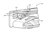
- FIG. 3 illustrates a non-limiting example of a female terminal 222 incorporating the inventive features.
- the illustrated example includes a pair of longitudinal protrusions 224 or contact ridges 224 that are formed in a top surface 226 of a resilient contact arm 228 by an embossing process.
- a leading edge 230 of the contact ridge 224 forms ramp 234 that defines an angle ⁇ relative to the top surface 226 of the contact arm 228 that is greater than 0 degrees and less than or equal to 30 degrees.
- This contact ridge 224 is foamed by an embossing process using specially designed tooling to obtain the desired ramp angle ⁇ .
- FIG. 4 illustrates a comparison of the leading edge 130 of the female terminal 122 shown in dotted outline versus the leading edge 230 of the female terminal 222 shown with a solid line.
- the ramp 234 in the illustrated example has an angle ⁇ of about 10 degrees. As used herein, about 10 degrees is in the range between 7.5 and 12.5 degrees. As can be seen, the ramp 234 on the leading edge 230 has a much less abrupt transition than the leading edge 130 .
- the heights of the ridges at the apex of each of the contact arm 128 , 228 i.e. the point at which the contact arm interfaces with the male terminal, is the same in both female terminals 122 , 222 .
- the female terminal 222 therefore provides the same final contact force as the female terminal 122 .
- FIG. 5 shows a comparison the test results of engagement for the female terminal 122 and the female terminal 222 , wherein the female terminal 222 has a ramp angle ⁇ of about 10 degrees.
- the minimum 236 , maximum 238, and average 240 peak engagement force of female terminal 222 is reduced by about 37% compared to the minimum 136 , maximum 138, and average 140 peak engagement force of female terminal 222 while maintaining the same standard deviation 242 , 142 and while still providing the same final contact force.
- While the illustrated embodiments include a pair of contacts ridges, alternative embodiments may be envisioned having a single contact ridge or more than two contact ridges. While the ramp in the illustrated example is formed during the embossing process, embodiments using other methods to form the ramp, such as grinding or material deposition. The ramp on the leading edge may also be applied to other terminal designs, including male bladed terminals in order to reduce peak engagement force.
- an electrical connection system 10 having a female terminal 222 is provided.
- the ramps 234 formed on the leading edges of the contact ridges 224 of the female terminal 222 provide the benefit of a point contact between the male terminal and the female terminal 222 while reducing the peak engagement force 236 , 238 , 240 experienced by an operator when mating the female and male terminals.
Landscapes
- Connector Housings Or Holding Contact Members (AREA)
- Details Of Connecting Devices For Male And Female Coupling (AREA)
Abstract
Description
Claims (12)
Priority Applications (4)
| Application Number | Priority Date | Filing Date | Title |
|---|---|---|---|
| US15/280,522 US10090608B2 (en) | 2016-09-29 | 2016-09-29 | Electrical connection system having a terminal with contact ridges |
| KR1020170123899A KR20180035690A (en) | 2016-09-29 | 2017-09-26 | Electrical conenction system having a terminal with conatct ridges |
| EP17193092.8A EP3301762A1 (en) | 2016-09-29 | 2017-09-26 | Electrical connection system having a terminal with contact ridges |
| CN201710897524.9A CN107887732B (en) | 2016-09-29 | 2017-09-28 | Electrical connection system with terminals with contact ridges |
Applications Claiming Priority (1)
| Application Number | Priority Date | Filing Date | Title |
|---|---|---|---|
| US15/280,522 US10090608B2 (en) | 2016-09-29 | 2016-09-29 | Electrical connection system having a terminal with contact ridges |
Publications (2)
| Publication Number | Publication Date |
|---|---|
| US20180090854A1 US20180090854A1 (en) | 2018-03-29 |
| US10090608B2 true US10090608B2 (en) | 2018-10-02 |
Family
ID=59969041
Family Applications (1)
| Application Number | Title | Priority Date | Filing Date |
|---|---|---|---|
| US15/280,522 Active 2037-02-09 US10090608B2 (en) | 2016-09-29 | 2016-09-29 | Electrical connection system having a terminal with contact ridges |
Country Status (4)
| Country | Link |
|---|---|
| US (1) | US10090608B2 (en) |
| EP (1) | EP3301762A1 (en) |
| KR (1) | KR20180035690A (en) |
| CN (1) | CN107887732B (en) |
Cited By (4)
| Publication number | Priority date | Publication date | Assignee | Title |
|---|---|---|---|---|
| US10862226B2 (en) * | 2018-09-06 | 2020-12-08 | Yazaki Corporation | Terminal fitting |
| US11088471B2 (en) * | 2019-05-29 | 2021-08-10 | Yazaki Corporation | Terminal-attached electric wire and wire harness |
| US20220045452A1 (en) * | 2020-08-05 | 2022-02-10 | Aptiv Technologies Limited | Anti-fretting/multiple contact terminal using knurl pattern |
| US11646510B2 (en) | 2021-04-29 | 2023-05-09 | Aptiv Technologies Limited | Shielding electrical terminal with knurling on inner contact walls |
Families Citing this family (6)
| Publication number | Priority date | Publication date | Assignee | Title |
|---|---|---|---|---|
| JP6607141B2 (en) * | 2016-05-12 | 2019-11-20 | 住友電装株式会社 | Terminal |
| USD1044106S1 (en) * | 2019-12-20 | 2024-09-24 | Kh Feelux Co., Ltd. | Ceiling light |
| CN116325372A (en) * | 2020-09-21 | 2023-06-23 | 莫列斯有限公司 | Anti-wear terminal accessories |
| JP7466844B2 (en) * | 2020-12-11 | 2024-04-15 | 株式会社オートネットワーク技術研究所 | Terminal Unit |
| CN113270744B (en) * | 2021-04-26 | 2022-09-27 | 宣城立讯精密工业有限公司 | Electric connector and connector assembly |
| JP7754897B2 (en) * | 2023-09-14 | 2025-10-15 | 矢崎総業株式会社 | Terminals and wires with terminals |
Citations (9)
| Publication number | Priority date | Publication date | Assignee | Title |
|---|---|---|---|---|
| US20020055297A1 (en) | 1999-09-27 | 2002-05-09 | John V. Feeny | Modular female electrical terminal |
| EP1233475A2 (en) | 2001-02-15 | 2002-08-21 | Autonetworks Technologies, Ltd. | Terminal structure of connector |
| JP2011239372A (en) | 2010-04-14 | 2011-11-24 | Sharp Corp | Imaging apparatus |
| US8152576B2 (en) | 2009-12-02 | 2012-04-10 | Sumitomo Wiring Systems, Ltd. | Female terminal fitting |
| US8333622B2 (en) * | 2010-12-06 | 2012-12-18 | Delphi Technologies, Inc. | Dual contact beam terminal |
| US20140287635A1 (en) | 2013-03-21 | 2014-09-25 | Sumitomo Wiring Systems, Ltd. | Terminal fitting |
| US20150180166A1 (en) | 2012-09-04 | 2015-06-25 | Tyco Electronics (Shanghai) Co. Ltd. | Electrical Connector and Electrical Connector Assembly |
| JP2015153553A (en) | 2014-02-13 | 2015-08-24 | 株式会社オートネットワーク技術研究所 | Female terminal |
| US9118130B1 (en) | 2014-02-06 | 2015-08-25 | Delphi Technologies, Inc. | Low insertion force terminal |
Family Cites Families (6)
| Publication number | Priority date | Publication date | Assignee | Title |
|---|---|---|---|---|
| JP5282540B2 (en) * | 2008-11-21 | 2013-09-04 | 日立電線株式会社 | Male-female connection structure |
| JP2011238372A (en) * | 2010-05-06 | 2011-11-24 | Sumitomo Wiring Syst Ltd | Female terminal |
| JP5795740B2 (en) * | 2012-01-18 | 2015-10-14 | Dowaメタルテック株式会社 | Terminal structure |
| JP5999510B2 (en) * | 2013-05-30 | 2016-09-28 | 住友電装株式会社 | Female terminal fitting and manufacturing method thereof |
| JP2016018596A (en) * | 2014-07-04 | 2016-02-01 | 株式会社日本自動車部品総合研究所 | Connector structure |
| CN204304043U (en) * | 2014-12-31 | 2015-04-29 | 浙江合兴电子元件有限公司 | A kind of syndeton of bonder terminal |
-
2016
- 2016-09-29 US US15/280,522 patent/US10090608B2/en active Active
-
2017
- 2017-09-26 EP EP17193092.8A patent/EP3301762A1/en not_active Withdrawn
- 2017-09-26 KR KR1020170123899A patent/KR20180035690A/en not_active Ceased
- 2017-09-28 CN CN201710897524.9A patent/CN107887732B/en active Active
Patent Citations (10)
| Publication number | Priority date | Publication date | Assignee | Title |
|---|---|---|---|---|
| US20020055297A1 (en) | 1999-09-27 | 2002-05-09 | John V. Feeny | Modular female electrical terminal |
| EP1233475A2 (en) | 2001-02-15 | 2002-08-21 | Autonetworks Technologies, Ltd. | Terminal structure of connector |
| US6506084B2 (en) * | 2001-02-15 | 2003-01-14 | Autonetworks Technologies, Ltd. | Terminal structure of connector |
| US8152576B2 (en) | 2009-12-02 | 2012-04-10 | Sumitomo Wiring Systems, Ltd. | Female terminal fitting |
| JP2011239372A (en) | 2010-04-14 | 2011-11-24 | Sharp Corp | Imaging apparatus |
| US8333622B2 (en) * | 2010-12-06 | 2012-12-18 | Delphi Technologies, Inc. | Dual contact beam terminal |
| US20150180166A1 (en) | 2012-09-04 | 2015-06-25 | Tyco Electronics (Shanghai) Co. Ltd. | Electrical Connector and Electrical Connector Assembly |
| US20140287635A1 (en) | 2013-03-21 | 2014-09-25 | Sumitomo Wiring Systems, Ltd. | Terminal fitting |
| US9118130B1 (en) | 2014-02-06 | 2015-08-25 | Delphi Technologies, Inc. | Low insertion force terminal |
| JP2015153553A (en) | 2014-02-13 | 2015-08-24 | 株式会社オートネットワーク技術研究所 | Female terminal |
Cited By (5)
| Publication number | Priority date | Publication date | Assignee | Title |
|---|---|---|---|---|
| US10862226B2 (en) * | 2018-09-06 | 2020-12-08 | Yazaki Corporation | Terminal fitting |
| US11088471B2 (en) * | 2019-05-29 | 2021-08-10 | Yazaki Corporation | Terminal-attached electric wire and wire harness |
| US20220045452A1 (en) * | 2020-08-05 | 2022-02-10 | Aptiv Technologies Limited | Anti-fretting/multiple contact terminal using knurl pattern |
| US11387585B2 (en) * | 2020-08-05 | 2022-07-12 | Aptiv Technologies Limited | Anti-fretting/multiple contact terminal using knurl pattern |
| US11646510B2 (en) | 2021-04-29 | 2023-05-09 | Aptiv Technologies Limited | Shielding electrical terminal with knurling on inner contact walls |
Also Published As
| Publication number | Publication date |
|---|---|
| CN107887732A (en) | 2018-04-06 |
| CN107887732B (en) | 2020-06-09 |
| US20180090854A1 (en) | 2018-03-29 |
| EP3301762A1 (en) | 2018-04-04 |
| KR20180035690A (en) | 2018-04-06 |
Similar Documents
| Publication | Publication Date | Title |
|---|---|---|
| US10090608B2 (en) | Electrical connection system having a terminal with contact ridges | |
| US3409867A (en) | Detachable electrical connectors | |
| EP1990866B1 (en) | A female terminal fitting | |
| US9166322B2 (en) | Female electric terminal with gap between terminal beams | |
| CN101790819B (en) | Electrical contact | |
| US9293852B2 (en) | Electrical terminal assembly | |
| US5281175A (en) | Female electrical terminal | |
| JP6034755B2 (en) | Terminal structure | |
| EP1890363B1 (en) | A female terminal fitting | |
| EP1172893A2 (en) | Electrical receptacle terminal and connection structure thereof with pin terminal | |
| EP3769375B1 (en) | Connector position assurance member | |
| US10079440B1 (en) | Electrical terminal having a push surface | |
| US5281178A (en) | Electrical connector with feature for increased contact area | |
| CN105449408B (en) | Bonder terminal | |
| US5628656A (en) | High density pin and socket electrical connector | |
| US6629865B2 (en) | Zero terminal insertion force electrical connection assembly | |
| US8317553B2 (en) | Terminal fitting with an entrance preventing wall | |
| US5913694A (en) | Connector assembly | |
| CN117561652A (en) | high power connector | |
| US2359084A (en) | Crimping die for electrical connectors | |
| US20140206220A1 (en) | Connection system including connector body with integral primary and secondary lock | |
| US20090137161A1 (en) | Electrical contact with retention latch | |
| US4537462A (en) | Electrical connector | |
| EP3503306B1 (en) | Receptacle connector housing with hold-down ribs | |
| US9882324B2 (en) | Electrical connector assembly having identical matable connectors |
Legal Events
| Date | Code | Title | Description |
|---|---|---|---|
| AS | Assignment |
Owner name: DELPHI TECHNOLOGIES, INC., MICHIGAN Free format text: ASSIGNMENT OF ASSIGNORS INTEREST;ASSIGNOR:LEWIS, RYAN D.;REEL/FRAME:040350/0525 Effective date: 20161003 |
|
| STCF | Information on status: patent grant |
Free format text: PATENTED CASE |
|
| AS | Assignment |
Owner name: APTIV TECHNOLOGIES LIMITED, BARBADOS Free format text: ASSIGNMENT OF ASSIGNORS INTEREST;ASSIGNOR:DELPHI TECHNOLOGIES INC.;REEL/FRAME:047143/0874 Effective date: 20180101 |
|
| MAFP | Maintenance fee payment |
Free format text: PAYMENT OF MAINTENANCE FEE, 4TH YEAR, LARGE ENTITY (ORIGINAL EVENT CODE: M1551); ENTITY STATUS OF PATENT OWNER: LARGE ENTITY Year of fee payment: 4 |
|
| AS | Assignment |
Owner name: APTIV TECHNOLOGIES (2) S.A R.L., LUXEMBOURG Free format text: ENTITY CONVERSION;ASSIGNOR:APTIV TECHNOLOGIES LIMITED;REEL/FRAME:066746/0001 Effective date: 20230818 Owner name: APTIV MANUFACTURING MANAGEMENT SERVICES S.A R.L., LUXEMBOURG Free format text: MERGER;ASSIGNOR:APTIV TECHNOLOGIES (2) S.A R.L.;REEL/FRAME:066566/0173 Effective date: 20231005 Owner name: APTIV TECHNOLOGIES AG, SWITZERLAND Free format text: ASSIGNMENT OF ASSIGNORS INTEREST;ASSIGNOR:APTIV MANUFACTURING MANAGEMENT SERVICES S.A R.L.;REEL/FRAME:066551/0219 Effective date: 20231006 |
|
| MAFP | Maintenance fee payment |
Free format text: PAYMENT OF MAINTENANCE FEE, 8TH YEAR, LARGE ENTITY (ORIGINAL EVENT CODE: M1552); ENTITY STATUS OF PATENT OWNER: LARGE ENTITY Year of fee payment: 8 |