US10088839B2 - Method and system for real-time performance degradation advisory for centrifugal compressors - Google Patents
Method and system for real-time performance degradation advisory for centrifugal compressors Download PDFInfo
- Publication number
- US10088839B2 US10088839B2 US14/382,063 US201314382063A US10088839B2 US 10088839 B2 US10088839 B2 US 10088839B2 US 201314382063 A US201314382063 A US 201314382063A US 10088839 B2 US10088839 B2 US 10088839B2
- Authority
- US
- United States
- Prior art keywords
- centrifugal compressor
- performance
- compressor
- actual
- real
- Prior art date
- Legal status (The legal status is an assumption and is not a legal conclusion. Google has not performed a legal analysis and makes no representation as to the accuracy of the status listed.)
- Active, expires
Links
Images


Classifications
-
- G—PHYSICS
- G05—CONTROLLING; REGULATING
- G05B—CONTROL OR REGULATING SYSTEMS IN GENERAL; FUNCTIONAL ELEMENTS OF SUCH SYSTEMS; MONITORING OR TESTING ARRANGEMENTS FOR SUCH SYSTEMS OR ELEMENTS
- G05B23/00—Testing or monitoring of control systems or parts thereof
- G05B23/02—Electric testing or monitoring
- G05B23/0205—Electric testing or monitoring by means of a monitoring system capable of detecting and responding to faults
- G05B23/0218—Electric testing or monitoring by means of a monitoring system capable of detecting and responding to faults characterised by the fault detection method dealing with either existing or incipient faults
- G05B23/0224—Process history based detection method, e.g. whereby history implies the availability of large amounts of data
- G05B23/0227—Qualitative history assessment, whereby the type of data acted upon, e.g. waveforms, images or patterns, is not relevant, e.g. rule based assessment; if-then decisions
- G05B23/0235—Qualitative history assessment, whereby the type of data acted upon, e.g. waveforms, images or patterns, is not relevant, e.g. rule based assessment; if-then decisions based on a comparison with predetermined threshold or range, e.g. "classical methods", carried out during normal operation; threshold adaptation or choice; when or how to compare with the threshold
-
- G—PHYSICS
- G05—CONTROLLING; REGULATING
- G05B—CONTROL OR REGULATING SYSTEMS IN GENERAL; FUNCTIONAL ELEMENTS OF SUCH SYSTEMS; MONITORING OR TESTING ARRANGEMENTS FOR SUCH SYSTEMS OR ELEMENTS
- G05B19/00—Programme-control systems
- G05B19/02—Programme-control systems electric
- G05B19/04—Programme control other than numerical control, i.e. in sequence controllers or logic controllers
- G05B19/042—Programme control other than numerical control, i.e. in sequence controllers or logic controllers using digital processors
- G05B19/0421—Multiprocessor system
-
- F—MECHANICAL ENGINEERING; LIGHTING; HEATING; WEAPONS; BLASTING
- F01—MACHINES OR ENGINES IN GENERAL; ENGINE PLANTS IN GENERAL; STEAM ENGINES
- F01D—NON-POSITIVE DISPLACEMENT MACHINES OR ENGINES, e.g. STEAM TURBINES
- F01D21/00—Shutting-down of machines or engines, e.g. in emergency; Regulating, controlling, or safety means not otherwise provided for
- F01D21/003—Arrangements for testing or measuring
-
- F—MECHANICAL ENGINEERING; LIGHTING; HEATING; WEAPONS; BLASTING
- F02—COMBUSTION ENGINES; HOT-GAS OR COMBUSTION-PRODUCT ENGINE PLANTS
- F02C—GAS-TURBINE PLANTS; AIR INTAKES FOR JET-PROPULSION PLANTS; CONTROLLING FUEL SUPPLY IN AIR-BREATHING JET-PROPULSION PLANTS
- F02C7/00—Features, components parts, details or accessories, not provided for in, or of interest apart form groups F02C1/00 - F02C6/00; Air intakes for jet-propulsion plants
-
- G—PHYSICS
- G01—MEASURING; TESTING
- G01L—MEASURING FORCE, STRESS, TORQUE, WORK, MECHANICAL POWER, MECHANICAL EFFICIENCY, OR FLUID PRESSURE
- G01L3/00—Measuring torque, work, mechanical power, or mechanical efficiency, in general
- G01L3/02—Rotary-transmission dynamometers
- G01L3/04—Rotary-transmission dynamometers wherein the torque-transmitting element comprises a torsionally-flexible shaft
- G01L3/10—Rotary-transmission dynamometers wherein the torque-transmitting element comprises a torsionally-flexible shaft involving electric or magnetic means for indicating
-
- G—PHYSICS
- G01—MEASURING; TESTING
- G01M—TESTING STATIC OR DYNAMIC BALANCE OF MACHINES OR STRUCTURES; TESTING OF STRUCTURES OR APPARATUS, NOT OTHERWISE PROVIDED FOR
- G01M15/00—Testing of engines
- G01M15/14—Testing gas-turbine engines or jet-propulsion engines
-
- G—PHYSICS
- G05—CONTROLLING; REGULATING
- G05B—CONTROL OR REGULATING SYSTEMS IN GENERAL; FUNCTIONAL ELEMENTS OF SUCH SYSTEMS; MONITORING OR TESTING ARRANGEMENTS FOR SUCH SYSTEMS OR ELEMENTS
- G05B23/00—Testing or monitoring of control systems or parts thereof
- G05B23/02—Electric testing or monitoring
- G05B23/0205—Electric testing or monitoring by means of a monitoring system capable of detecting and responding to faults
- G05B23/0208—Electric testing or monitoring by means of a monitoring system capable of detecting and responding to faults characterized by the configuration of the monitoring system
- G05B23/0216—Human interface functionality, e.g. monitoring system providing help to the user in the selection of tests or in its configuration
-
- G—PHYSICS
- G05—CONTROLLING; REGULATING
- G05B—CONTROL OR REGULATING SYSTEMS IN GENERAL; FUNCTIONAL ELEMENTS OF SUCH SYSTEMS; MONITORING OR TESTING ARRANGEMENTS FOR SUCH SYSTEMS OR ELEMENTS
- G05B23/00—Testing or monitoring of control systems or parts thereof
- G05B23/02—Electric testing or monitoring
- G05B23/0205—Electric testing or monitoring by means of a monitoring system capable of detecting and responding to faults
- G05B23/0218—Electric testing or monitoring by means of a monitoring system capable of detecting and responding to faults characterised by the fault detection method dealing with either existing or incipient faults
-
- G—PHYSICS
- G05—CONTROLLING; REGULATING
- G05B—CONTROL OR REGULATING SYSTEMS IN GENERAL; FUNCTIONAL ELEMENTS OF SUCH SYSTEMS; MONITORING OR TESTING ARRANGEMENTS FOR SUCH SYSTEMS OR ELEMENTS
- G05B23/00—Testing or monitoring of control systems or parts thereof
- G05B23/02—Electric testing or monitoring
- G05B23/0205—Electric testing or monitoring by means of a monitoring system capable of detecting and responding to faults
- G05B23/0259—Electric testing or monitoring by means of a monitoring system capable of detecting and responding to faults characterized by the response to fault detection
- G05B23/0267—Fault communication, e.g. human machine interface [HMI]
- G05B23/0272—Presentation of monitored results, e.g. selection of status reports to be displayed; Filtering information to the user
-
- G—PHYSICS
- G05—CONTROLLING; REGULATING
- G05B—CONTROL OR REGULATING SYSTEMS IN GENERAL; FUNCTIONAL ELEMENTS OF SUCH SYSTEMS; MONITORING OR TESTING ARRANGEMENTS FOR SUCH SYSTEMS OR ELEMENTS
- G05B23/00—Testing or monitoring of control systems or parts thereof
- G05B23/02—Electric testing or monitoring
- G05B23/0205—Electric testing or monitoring by means of a monitoring system capable of detecting and responding to faults
- G05B23/0259—Electric testing or monitoring by means of a monitoring system capable of detecting and responding to faults characterized by the response to fault detection
- G05B23/0283—Predictive maintenance, e.g. involving the monitoring of a system and, based on the monitoring results, taking decisions on the maintenance schedule of the monitored system; Estimating remaining useful life [RUL]
-
- H—ELECTRICITY
- H04—ELECTRIC COMMUNICATION TECHNIQUE
- H04L—TRANSMISSION OF DIGITAL INFORMATION, e.g. TELEGRAPHIC COMMUNICATION
- H04L67/00—Network arrangements or protocols for supporting network services or applications
- H04L67/01—Protocols
- H04L67/10—Protocols in which an application is distributed across nodes in the network
-
- F—MECHANICAL ENGINEERING; LIGHTING; HEATING; WEAPONS; BLASTING
- F01—MACHINES OR ENGINES IN GENERAL; ENGINE PLANTS IN GENERAL; STEAM ENGINES
- F01D—NON-POSITIVE DISPLACEMENT MACHINES OR ENGINES, e.g. STEAM TURBINES
- F01D21/00—Shutting-down of machines or engines, e.g. in emergency; Regulating, controlling, or safety means not otherwise provided for
- F01D21/12—Shutting-down of machines or engines, e.g. in emergency; Regulating, controlling, or safety means not otherwise provided for responsive to temperature
-
- F—MECHANICAL ENGINEERING; LIGHTING; HEATING; WEAPONS; BLASTING
- F02—COMBUSTION ENGINES; HOT-GAS OR COMBUSTION-PRODUCT ENGINE PLANTS
- F02C—GAS-TURBINE PLANTS; AIR INTAKES FOR JET-PROPULSION PLANTS; CONTROLLING FUEL SUPPLY IN AIR-BREATHING JET-PROPULSION PLANTS
- F02C9/00—Controlling gas-turbine plants; Controlling fuel supply in air- breathing jet-propulsion plants
-
- F—MECHANICAL ENGINEERING; LIGHTING; HEATING; WEAPONS; BLASTING
- F04—POSITIVE - DISPLACEMENT MACHINES FOR LIQUIDS; PUMPS FOR LIQUIDS OR ELASTIC FLUIDS
- F04B—POSITIVE-DISPLACEMENT MACHINES FOR LIQUIDS; PUMPS
- F04B51/00—Testing machines, pumps, or pumping installations
-
- F—MECHANICAL ENGINEERING; LIGHTING; HEATING; WEAPONS; BLASTING
- F05—INDEXING SCHEMES RELATING TO ENGINES OR PUMPS IN VARIOUS SUBCLASSES OF CLASSES F01-F04
- F05D—INDEXING SCHEME FOR ASPECTS RELATING TO NON-POSITIVE-DISPLACEMENT MACHINES OR ENGINES, GAS-TURBINES OR JET-PROPULSION PLANTS
- F05D2260/00—Function
- F05D2260/80—Diagnostics
-
- G—PHYSICS
- G01—MEASURING; TESTING
- G01K—MEASURING TEMPERATURE; MEASURING QUANTITY OF HEAT; THERMALLY-SENSITIVE ELEMENTS NOT OTHERWISE PROVIDED FOR
- G01K13/00—Thermometers specially adapted for specific purposes
-
- G—PHYSICS
- G05—CONTROLLING; REGULATING
- G05B—CONTROL OR REGULATING SYSTEMS IN GENERAL; FUNCTIONAL ELEMENTS OF SUCH SYSTEMS; MONITORING OR TESTING ARRANGEMENTS FOR SUCH SYSTEMS OR ELEMENTS
- G05B11/00—Automatic controllers
- G05B11/01—Automatic controllers electric
- G05B11/06—Automatic controllers electric in which the output signal represents a continuous function of the deviation from the desired value, i.e. continuous controllers
-
- G—PHYSICS
- G05—CONTROLLING; REGULATING
- G05B—CONTROL OR REGULATING SYSTEMS IN GENERAL; FUNCTIONAL ELEMENTS OF SUCH SYSTEMS; MONITORING OR TESTING ARRANGEMENTS FOR SUCH SYSTEMS OR ELEMENTS
- G05B2219/00—Program-control systems
- G05B2219/20—Pc systems
- G05B2219/25—Pc structure of the system
- G05B2219/25315—Module, sequence from module to module, structure
-
- G—PHYSICS
- G05—CONTROLLING; REGULATING
- G05B—CONTROL OR REGULATING SYSTEMS IN GENERAL; FUNCTIONAL ELEMENTS OF SUCH SYSTEMS; MONITORING OR TESTING ARRANGEMENTS FOR SUCH SYSTEMS OR ELEMENTS
- G05B23/00—Testing or monitoring of control systems or parts thereof
- G05B23/02—Electric testing or monitoring
- G05B23/0205—Electric testing or monitoring by means of a monitoring system capable of detecting and responding to faults
- G05B23/0218—Electric testing or monitoring by means of a monitoring system capable of detecting and responding to faults characterised by the fault detection method dealing with either existing or incipient faults
- G05B23/0243—Electric testing or monitoring by means of a monitoring system capable of detecting and responding to faults characterised by the fault detection method dealing with either existing or incipient faults model based detection method, e.g. first-principles knowledge model
- G05B23/0245—Electric testing or monitoring by means of a monitoring system capable of detecting and responding to faults characterised by the fault detection method dealing with either existing or incipient faults model based detection method, e.g. first-principles knowledge model based on a qualitative model, e.g. rule based; if-then decisions
Definitions
- This description relates to generally to mechanical/electrical equipment operations, monitoring and diagnostics, and more specifically, to systems and methods for automatically advising operators of anomalous behavior of machinery.
- Monitoring machinery performance and alerting operators to anomalous conditions that can impact performance is an important part of operating one or a fleet of machines.
- Relatively simple known monitoring systems lack detailed design information that would permit them to not only monitor centrifugal compressors but also analyze performance degradation online in real-time and recommend trouble-shooting steps required to localize and mitigate the performance degradation.
- current monitoring systems do not typically adjust thresholds based on compressor load or other operating conditions. Using only static thresholds permits false positive alarms. Without this calculation, only static thresholds based on constant deviation from preset values is available.
- rapidly changing operational conditions or very slowly changing operational conditions may make it difficult for an operator to recognize anomalous conditions or what operational changes can be made to mitigate the anomalous conditions.
- a computer-implemented method for generating real-time performance advisories for a centrifugal compressor of a fleet of centrifugal compressors includes receiving an actual thermodynamic signature of the compressor, that is unique to the compressor, receiving compressor process parameter values during operation of the compressor, determining, in real-time, an actual performance of the compressor using the compressor process parameter values, determining, in real-time, a predicted performance of the compressor using the received actual thermodynamic signature of the compressor, determining a performance deviation of the compressor using the actual performance and the predicted performance, comparing the performance deviation to a predetermined threshold range of performance deviation, and generating a notification to a user using the comparison.
- a compressor monitoring and diagnostic system for a gas turbine including a centrifugal compressor and a low pressure turbine in flow communication
- the system includes a centrifugal compressor performance rule set, the rule set including a subset of a plurality of actual thermodynamic signatures for a fleet of centrifugal compressors and a relational expression of a real-time data output relative to a real-time data input, where the subset includes an actual thermodynamic signature of the compressor, and the relational expression is specific to a inputs relating to an operational performance of the centrifugal compressor
- the rule set is configured to determine a performance deviation of the compressor using an actual performance of the compressor and a predicted performance of the compressor, compare the performance deviation to a predetermined threshold range of performance deviation, and generate a notification to a user using the comparison.
- one or more non-transitory computer-readable storage media has computer-executable instructions embodied thereon, wherein when executed by at least one processor, the computer-executable instructions cause the processor to receive compressor process parameter values during operation of the compressor, determine, in real-time, an actual performance of the compressor using the compressor process parameter values, determine, in real-time, a predicted performance of the compressor using the received actual thermodynamic signature of the compressor, determine a performance deviation of the compressor using an actual performance of the compressor and a predicted performance of the compressor, compare the performance deviation to a predetermined threshold range of performance deviation, and generate a notification to a user using the comparison.
- FIGS. 1-7 show exemplary embodiments of the method and system described herein.
- FIG. 1 is a schematic block diagram of a remote monitoring and diagnostic system in accordance with an exemplary embodiment of the present invention
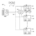
- FIG. 2 is a block diagram of an exemplary embodiment of a network architecture of a local industrial plant monitoring and diagnostic system, such as a distributed control system (DCS);
- DCS distributed control system
- FIG. 3 is a block diagram of an exemplary rule set that may be used with LMDS shown in FIG. 1 ;
- FIG. 4 is a schematic flow diagram for generating a real-time actual performance calculation for a centrifugal compressor in accordance with an exemplary embodiment of the present disclosure.
- FIG. 5 is a schematic flow diagram for generating a real-time expected performance calculation for centrifugal compressor in accordance with an exemplary embodiment of the present disclosure.
- FIG. 6 is a screen capture of a performance module screen for the compressor illustrating a visual depiction between actual to expected performance of the compressor.
- FIG. 7 is a flow diagram of a method of the compressor performance calculation details.
- centrifugal compressor performance rule set described herein permits operators to know when their machine is not operating as efficiently as possible or as efficiently as it once. Knowing the design criteria, as received from the OEM of the compressor permits accurate real-time performance display for quick assessment of problems and permits detailed assessments of possible sources of the problems.
- a real-time compressor performance advisory for centrifugal compressors calculates the ‘actual’ and ‘expected’ performance of the machine using the OEM design tools in place of existing non-physics based methodologies provides higher calculation accuracies.
- the expected and actual performance calculations are carried out at, for example, one minute intervals and any anomalous deviation is notified to a user.
- the deviation in threshold along with the time persistence of the deviation determines the decision to notify the user.
- the performance degradation advisory provides the various actions in steps to be performed to identify the possible sources of the cause.
- the calculation methodology used for ‘expected performance’ permits each compressor operator real-time performance envelopes for each snap shot of data supplied from the monitoring controllers to avoid using only a static performance envelope supplied one-time by the OEM during machine commissioning.
- Centrifugal compressors are dynamic machines and highly sensitive to the system resistance and impeller velocities.
- the system resistance and impeller velocities are governed by the gas composition and operating conditions. Performance of these machines can deteriorate due to poor operating condition or due to flow passage changes (deposition).
- Accurate performance estimation, their interpretation and providing follow-up action (advisory) still remains a challenging task mainly due to wide variation in operating conditions within OEM envelope and limitation of static baseline or static OEM operating envelope.
- the methods described herein dynamically generate the compressor baseline or ‘expected performance’ in real-time at predetermined intervals using monitoring system data.
- the dynamic OEM envelope is more realistic to the current operating condition as against the static envelope.
- a methodology is developed to track the deviation in actual performance from the dynamic baseline bearing in mind the varying machine operating conditions.
- the OEM design tools are used for the estimation of actual and expected performances respectively.
- the OEM ‘As Tested’ curves are embedded to perform the calculations.
- real-time refers to outcomes occurring at a substantially short period after a change in the inputs affecting the outcome, for example, computational calculations and/or element linking
- the period may be an amount of time between iterations of a regularly repeated task. Such repeated tasks are called periodic tasks.
- the time period is a design parameter of the real-time system that may be selected based on the importance of the outcome and/or the capability of the system implementing processing of the inputs to generate the outcome. Additionally, events occurring in real-time occur without substantial intentional delay.
- links are updated and mutations are fired in real-time within network and component capabilities.
- FIG. 1 is a schematic block diagram of remote monitoring and diagnostic system 100 in accordance with an exemplary embodiment of the present invention.
- system 100 includes a remote monitoring and diagnostic center 102 .
- Remote monitoring and diagnostic center 102 is operated by an entity, such as, an OEM of a plurality of equipment purchased and operated by a separate business entity, such as, an operating entity.
- the OEM and operating entity enter into a support arrangement whereby the OEM provides services related to the purchased equipment to the operating entity.
- the operating entity may own and operate purchased equipment at a single site or multiple sites.
- the OEM may enter into support arrangements with a plurality of operating entities, each operating their own single site or multiple sites.
- the multiple sites each may contain identical individual equipment or pluralities of identical sets of equipment, such as trains of equipment. Additionally, at least some of the equipment may be unique to a site or unique to all sites.
- a first site 104 includes one or more process analyzers 106 , equipment monitoring systems 108 , equipment local control centers 110 , and/or monitoring and alarm panels 112 each configured to interface with respective equipment sensors and control equipment to effect control and operation of the respective equipment.
- the one or more process analyzers 106 , equipment monitoring systems 108 , equipment local control centers 110 , and/or monitoring and alarm panels 112 are communicatively coupled to an intelligent monitoring and diagnostic system 114 through a network 116 .
- Intelligent monitoring and diagnostic (IMAD) system 114 is further configured to communicate with other on-site systems (not shown in FIG. 1 ) and offsite systems, such as, but not limited to, remote monitoring and diagnostic center 102 .
- IMAD 114 is configured to communicate with remote monitoring and diagnostic center 102 using for example, a dedicated network 118 , a wireless link 120 , and the Internet 122 .
- Each of a plurality of other sites may be substantially similar to first site 104 although may or may not be exactly similar to first site 104 .
- FIG. 2 is a block diagram of an exemplary embodiment of a network architecture 200 of a local industrial plant monitoring and diagnostic system, such as a distributed control system (DCS) 201 .
- the industrial plant may include a plurality of plant equipment, such as gas turbines, centrifugal compressors, gearboxes, generators, pumps, motors, fans, and process monitoring sensors that are coupled in flow communication through interconnecting piping, and coupled in signal communication with DCS 201 through one or more remote input/output (I/O) modules and interconnecting cabling and/or wireless communication.
- the industrial plant includes DCS 201 including a network backbone 203 .
- Network backbone 203 may be a hardwired data communication path fabricated from twisted pair cable, shielded coaxial cable or fiber optic cable, for example, or may be at least partially wireless.
- DCS 201 may also include a processor 205 that is communicatively coupled to the plant equipment, located at the industrial plant site or at remote locations, through network backbone 203 . It is to be understood that any number of machines may be operatively connected to network backbone 203 . A portion of the machines may be hardwired to network backbone 203 , and another portion of the machines may be wirelessly coupled to backbone 203 via a wireless base station 207 that is communicatively coupled to DCS 201 .
- Wireless base station 207 may be used to expand the effective communication range of DCS 201 , such as with equipment or sensors located remotely from the industrial plant but, still interconnected to one or more systems within the industrial plant.
- DCS 201 may be configured to receive and display operational parameters associated with a plurality of equipment, and to generate automatic control signals and receive manual control inputs for controlling the operation of the equipment of industrial plant.
- DCS 201 may include a software code segment configured to control processor 205 to analyze data received at DCS 201 that allows for on-line monitoring and diagnosis of the industrial plant machines. Data may be collected from each machine, including gas turbines, centrifugal compressors, pumps and motors, associated process sensors, and local environmental sensors including, for example, vibration, seismic, temperature, pressure, current, voltage, ambient temperature and ambient humidity sensors. The data may be pre-processed by a local diagnostic module or a remote input/output module, or may be transmitted to DCS 201 in raw form.
- a local monitoring and diagnostic system (LMDS) 213 may be a separate add-on hardware device, such as, for example, a personal computer (PC), that communicates with DCS 201 and other control systems 209 and data sources through network backbone 203 .
- LMDS 213 may also be embodied in a software program segment executing on DCS 201 and/or one or more of the other control systems 209 . Accordingly, LMDS 213 may operate in a distributed manner, such that a portion of the software program segment executes on several processors concurrently. As such, LMDS 213 may be fully integrated into the operation of DCS 201 and other control systems 209 .
- LMDS 213 analyzes data received by DCS 201 , data sources, and other control systems 209 to determine an operational health of the machines and/or a process employing the machines using a global view of the industrial plant.
- network architecture 100 includes a server grade computer 202 and one or more client systems 203 .
- Server grade computer 202 further includes a database server 206 , an application server 208 , a web server 210 , a fax server 212 , a directory server 214 , and a mail server 216 .
- Each of servers 206 , 208 , 210 , 212 , 214 , and 216 may be embodied in software executing on server grade computer 202 , or any combinations of servers 206 , 208 , 210 , 212 , 214 , and 216 may be embodied alone or in combination on separate server grade computers coupled in a local area network (LAN) (not shown).
- LAN local area network
- a data storage unit 220 is coupled to server grade computer 202 .
- a workstation 222 such as a system administrator's workstation, a user workstation, and/or a supervisor's workstation are coupled to network backbone 203 .
- workstations 222 are coupled to network backbone 203 using an Internet link 226 or are connected through a wireless connection, such as, through wireless base station 207 .
- Each workstation 222 may be a personal computer having a web browser. Although the functions performed at the workstations typically are illustrated as being performed at respective workstations 222 , such functions can be performed at one of many personal computers coupled to network backbone 203 . Workstations 222 are described as being associated with separate exemplary functions only to facilitate an understanding of the different types of functions that can be performed by individuals having access to network backbone 203 .
- Server grade computer 202 is configured to be communicatively coupled to various individuals, including employees 228 and to third parties, e.g., service providers 230 .
- the communication in the exemplary embodiment is illustrated as being performed using the Internet, however, any other wide area network (WAN) type communication can be utilized in other embodiments, i.e., the systems and processes are not limited to being practiced using the Internet.
- WAN wide area network
- any authorized individual having a workstation 232 can access LMDS 213 .
- At least one of the client systems may include a manager workstation 234 located at a remote location.
- Workstations 222 may be embodied on personal computers having a web browser.
- workstations 222 are configured to communicate with server grade computer 202 .
- fax server 212 communicates with remotely located client systems, including a client system 236 using a telephone link (not shown). Fax server 212 is configured to communicate with other client systems 228 , 230 , and 234 , as well.
- Computerized modeling and analysis tools of LMDS 213 may be stored in server 202 and can be accessed by a requester at any one of client systems 204 .
- client systems 204 are computers including a web browser, such that server grade computer 202 is accessible to client systems 204 using the Internet.
- Client systems 204 are interconnected to the Internet through many interfaces including a network, such as a local area network (LAN) or a wide area network (WAN), dial-in-connections, cable modems and special high-speed ISDN lines.
- Client systems 204 could be any device capable of interconnecting to the Internet including a web-based phone, personal digital assistant (PDA), or other web-based connectable equipment.
- PDA personal digital assistant
- Database server 206 is connected to a database 240 containing information about industrial plant 10 , as described below in greater detail.
- centralized database 240 is stored on server grade computer 202 and can be accessed by potential users at one of client systems 204 by logging onto server grade computer 202 through one of client systems 204 .
- database 240 is stored remotely from server grade computer 202 and may be non-centralized.
- Other industrial plant systems may provide data that is accessible to server grade computer 202 and/or client systems 204 through independent connections to network backbone 204 .
- An interactive electronic tech manual server 242 services requests for machine data relating to a configuration of each machine.
- Such data may include operational capabilities, such as pump curves, motor horsepower rating, insulation class, and frame size, design parameters, such as dimensions, number of rotor bars or impeller blades, and machinery maintenance history, such as field alterations to the machine, as-found and as-left alignment measurements, and repairs implemented on the machine that do not return the machine to its original design condition.
- a portable vibration monitor 244 may be intermittently coupled to LAN directly or through a computer input port such as ports included in workstations 222 or client systems 204 .
- vibration data is collected in a route, collecting data from a predetermined list of machines on a periodic basis, for example, monthly or other periodicity. Vibration data may also be collected in conjunction with troubleshooting, maintenance, and commissioning activities. Further, vibration data may be collected continuously in a real-time or near real-time basis. Such data may provide a new baseline for algorithms of LMDS 213 . Process data may similarly, be collected on a route basis or during troubleshooting, maintenance, and commissioning activities. Moreover, some process data may be collected continuously in a real-time or near real-time basis.
- process parameter data may not be permanently instrumented and a portable process data collector 245 may be used to collect process parameter data that can be downloaded to DCS 201 through workstation 222 so that it is accessible to LMDS 213 .
- Other process parameter data such as process fluid composition analyzers and pollution emission analyzers may be provided to DCS 201 through a plurality of on-line monitors 246 .
- Motor protection relay 248 associated with each machine.
- relays 248 are located remotely from the monitored equipment in a motor control center (MCC) or in switchgear 250 supplying the machine.
- MCC motor control center
- switchgear 250 may also include a supervisory control and data acquisition system (SCADA) that provides LMDS 213 with power supply or power delivery system (not shown) equipment located at the industrial plant, for example, in a switchyard, or remote transmission line breakers and line parameters.
- SCADA supervisory control and data acquisition system
- FIG. 3 is a block diagram of an exemplary rule set 280 that may be used with LMDS 213 (shown in FIG. 1 ).
- Rule set 280 may be a combination of one or more custom rules, and a series of properties that define the behavior and state of the custom rules. The rules and properties may be bundled and stored in a format of an XML string, which may be encrypted based on a 25 character alphanumeric key when stored to a file.
- Rule set 280 is a modular knowledge cell that includes one or more inputs 282 and one or more outputs 284 . Inputs 282 may be software ports that direct data from specific locations in LMDS 213 to rule set 280 .
- an input from a pump outboard vibration sensor may be transmitted to a hardware input termination in DCS 201 .
- DCS 201 may sample the signal at that termination to receive the signal thereon. The signal may then be processed and stored at a location in a memory accessible and/or integral to DCS 201 .
- a first input 286 of rule set 280 may be mapped to the location in memory such that the contents of the location in memory is available to rule set 280 as an input.
- an output 288 may be mapped to another location in the memory accessible to DCS 201 or to another memory such that the location in memory contains the output 288 of rule set 280 .
- rule set 280 includes one or more rules relating to monitoring and diagnosis of specific problems associated with equipment operating in an industrial plant, such as, for example, a gas reinjection plant, a liquid natural gas (LNG) plant, a power plant, a refinery, and a chemical processing facility.
- an industrial plant such as, for example, a gas reinjection plant, a liquid natural gas (LNG) plant, a power plant, a refinery, and a chemical processing facility.
- rule set 280 may be appropriately constructed to capture any knowledge and be used for determining solutions in any field.
- rule set 280 may contain knowledge pertaining to economic behavior, financial activity, weather phenomenon, and design processes. Rule set 280 may then be used to determine solutions to problems in these fields.
- Rule set 280 includes knowledge from one or many sources, such that the knowledge is transmitted to any system where rule set 280 is applied.
- Rule set 280 may include only rules specific to a specific plant asset and may be directed to only one possible problem associated with that specific plant asset.
- Rule set 280 may include only rules that are applicable to a motor or a motor/ pump combination.
- Rule set 280 may only include rules that determine a health of the motor/pump combination using vibration data.
- Rule set 280 may also include rules that determine the health of the motor/pump combination using a suite of diagnostic tools that include, in addition to vibration analysis techniques, but may also include, for example, performance calculational tools and/or financial calculational tools for the motor/pump combination.
- rule set 280 is created in a software developmental tool that prompts a user for relationships between inputs 282 and outputs 284 .
- Inputs 282 may receive data representing, for example digital signals, analog signals, waveforms, processed signals, manually entered and/or configuration parameters, and outputs from other rule sets.
- Rules within rule set 280 may include logical rules, numerical algorithms, application of waveform and signal processing techniques, expert system and artificial intelligence algorithms, statistical tools, and any other expression that may relate outputs 284 to inputs 282 .
- Outputs 284 may be mapped to respective locations in the memory that are reserved and configured to receive each output 284 .
- LMDS 213 and DCS 201 may then use the locations in memory to accomplish any monitoring and/or control functions LMDS 213 and DCS 201 may be programmed to perform.
- the rules of rule set 280 operate independently of LMDS 213 and DCS 201 , although inputs 282 may be supplied to rule set 280 and outputs 284 may be supplied to rule set 280 , directly or indirectly through intervening devices.
- rule set 280 a human expert in the field divulges knowledge of the field particular to a specific asset using a development tool by programming one or more rules.
- the rules are created by generating expressions of relationship between outputs 284 and inputs 282 such that no coding of the rules is needed.
- Operands may be selected from a library of operands, using graphical methods, for example, using drag and drop on a graphical user interface built into the development tool.
- a graphical representation of an operand may be selected from a library portion of a screen display (not shown) and dragged and dropped into a rule creation portion.
- rule set 280 may include a robust set of diagnostic and/or monitoring rules or a relatively less robust set of diagnostic and/or monitoring rules based on a customer's requirements and a state of the art in the particular field of rule set 280 .
- the development tool provides resources for testing rule set 280 during the development to ensure various combinations and values of inputs 282 produce expected outputs at outputs 284 .
- FIG. 4 is a schematic flow diagram for generating a real-time actual performance calculation for a centrifugal compressor 400 in accordance with an exemplary embodiment of the present disclosure.
- compressor process parameter values are acquired from for example, a plant monitoring system that acquires process data from a plurality of components throughout the plant or a compressor monitoring system (neither shown in FIG. 4 ) that acquires data associated with only compressor 400 .
- the compressor process parameter values include compressor suction process parameter values and compressor discharge process parameter values.
- the compressor suction process parameter values include, but are not limited to, a suction pressure [P in ] 402 and a suction temperature [T in ] 404 .
- the compressor discharge process parameter values include, but are not limited to, a discharge pressure [P out ] 406 and a discharge temperature [T out ] 408 .
- a mass flow 409 through compressor 400 , gas composition and gas molecular weight [M W ] and shaft rotating speed [rpm] are also acquired.
- the compressor process parameter values are applied to a polytrophic thermodynamic algorithm 410 using a more complete set of thermodynamic transformation and, more important, real gas behavior based on several equations of state to determine the actual performance of compressor 400 .
- polytrophic thermodynamic algorithm 410 and the compressor process parameter values are used to calculate a polytropic efficiency 412 , a polytropic head 414 , and an absorbed power 416 for compressor 400 .
- FIG. 5 is a schematic flow diagram for generating a real-time expected performance calculation for centrifugal compressor 400 in accordance with an exemplary embodiment of the present disclosure.
- compressor process parameter values are acquired from the plant monitoring system or the compressor monitoring system (neither shown in FIG. 4 ).
- the compressor process parameter values include compressor suction process parameter values.
- the compressor suction process parameter values include, but are not limited to, a suction pressure [P in ] 402 and a suction temperature [T in ] 404 .
- the compressor discharge process parameter values are values to be solved for by a compressor performance rule set 500 .
- the compressor discharge process parameter values to be solved for include, but are not limited to, an expected discharge pressure 502 and an expected discharge temperature 504 .
- compressor process parameter values and as-tested data 508 are applied to compressor performance rule set 500 to determine the expected performance of compressor 400 .
- compressor performance rule set 500 and the compressor process parameter values are used to calculate expected discharge pressure 502 , expected discharge temperature 504 , a polytropic efficiency 510 , a polytropic head 512 , and an absorbed power 514 for compressor 400 .
- FIG. 6 is a screen capture of a performance module screen 600 for compressor 400 illustrating a visual depiction between actual to expected performance of compressor 400 .
- Analysis of compressor 400 performed by compressor performance rule set 500 is displayed on a plurality of selectable tabs of performance module screen 600 .
- a monitoring tab 602 a performance tab 604 (selected in FIG. 6 ), an analysis tab 606 , and an information tab 608 .
- Performance module screen 600 includes a graph area 610 where graphical information is displayed, a performance parameter value area 612 , and an event and alarms area 614 for displaying information to a user, including a timestamp 616 , a source 618 , and a severity level 620 .
- FIG. 7 is a flow diagram of a method 700 of compressor performance calculation details.
- method 700 is a computer-implemented method for generating real-time performance advisories for a centrifugal compressor of a fleet of centrifugal compressors, method 700 is implemented using a computer device coupled to a user interface and a memory device.
- Method 700 includes receiving 702 compressor process parameter values during operation of the compressor.
- the on-line controller data such as inlet pressure/temperature, mass flow, gas composition, exit pressure/temperature and shaft speed is supplied to compressor performance rule set 500 at for example, an every minute interval.
- Method 700 includes generating 704 a variation notification if suction process parameter values of the received compressor process parameter values exceed a predetermined range.
- method 700 includes determining 706 , in real-time, an actual performance of the compressor using a polytrophic thermodynamic algorithm and the received inlet pressure/temperature, mass flow, gas composition, exit pressure/temperature and shaft speed.
- Method 700 also includes receiving 708 an actual thermodynamic signature of the compressor, that is unique to the compressor from the manufacturer of the compressor and which is a subset of a plurality of actual thermodynamic signatures for the fleet of centrifugal compressors, and determining 710 , in real-time, a predicted performance of the compressor using the actual thermodynamic signature of the compressor and using a more complete set of thermodynamic transformation and real gas behavior based on several equations of state.
- a performance deviation of the compressor is determined 712 using the actual performance and the predicted performance and the performance deviation is compared to a predetermined threshold range of performance deviation, and a severity of the performance deviation is determined 720 based on a degradation of compressor performance and a difficulty of mitigating the degradation.
- a notification to the user is generated 722 based on the determined severity.
- the notification includes correlating the performance deviation and the received compressor process parameter values to generate an advisory guiding the user with steps to identify the possible sources of a failure causing the deviation.
- method 700 also includes determining one or more key performance indicators (KPI) for the operation of the compressor using the thermodynamic signature specific to the compressor and comparing the one or more KPIs to the actual performance to generate one or more KPI performance deviations associated with the one or more KPIs.
- KPI key performance indicators
- a notification to the user is generated regarding each KPI performance deviation that exceeds a predetermined KPI performance deviation threshold range.
- determining 706 the actual performance of the compressor and determining 710 the predicted performance of the compressor are corrected based on a load on the compressor.
- Method 700 also includes determining 714 , in real-time, a predicted envelope of the compressor using the determined actual thermodynamic signature of the compressor, generating 716 a performance map using the predicted envelope and the actual performance, and outputting 718 an advisory message based on the generated performance map.
- Compressor performance rule set 500 provides high accuracy OEM tools to calculate the realistic expected performance in real-time, performance deviation alarms that considering the wide variation in operational conditions, and actionable alarm advisories and performance advisories based on the nature/degree of the deviation.
- the particular naming of the components, capitalization of terms, the attributes, data structures, or any other programming or structural aspect is not mandatory or significant, and the mechanisms that implement the invention or its features may have different names, formats, or protocols.
- the system may be implemented via a combination of hardware and software, as described, or entirely in hardware elements.
- the particular division of functionality between the various system components described herein is merely one example, and not mandatory; functions performed by a single system component may instead be performed by multiple components, and functions performed by multiple components may instead performed by a single component.
- processor refers to central processing units, microprocessors, microcontrollers, reduced instruction set circuits (RISC), application specific integrated circuits (ASIC), logic circuits, and any other circuit or processor capable of executing the functions described herein.
- RISC reduced instruction set circuits
- ASIC application specific integrated circuits
- the terms “software” and “firmware” are interchangeable, and include any computer program stored in memory for execution by processor 205 , including RAM memory, ROM memory, EPROM memory, EEPROM memory, and non-volatile RAM (NVRAM) memory.
- RAM memory random access memory
- ROM memory read-only memory
- EPROM memory erasable programmable read-only memory
- EEPROM memory electrically erasable programmable read-only memory
- NVRAM non-volatile RAM
- the above-described embodiments of the disclosure may be implemented using computer programming or engineering techniques including computer software, firmware, hardware or any combination or subset thereof, wherein the technical effect includes (a) receiving an actual thermodynamic signature of the compressor, that is unique to the compressor, (b) receiving compressor process parameter values during operation of the compressor, (c) determining, in real-time, an actual performance of the compressor using the compressor process parameter values, (d) determining, in real-time, a predicted performance of the compressor using the determined actual thermodynamic signature of the compressor, (e) determining a performance deviation of the compressor using the actual performance and the predicted performance, (f) comparing the performance deviation to a predetermined threshold range of performance deviation (g) generating a notification to a user using the comparison, (h) determining one or more key performance indicators (KPI) for the operation of the compressor using the thermodynamic signature specific to the compressor, (i) comparing the one or more KPIs to the actual performance to generate one or more KPI performance deviations associated with the
- Any such resulting program, having computer-readable code means, may be embodied or provided within one or more computer-readable media, thereby making a computer program product, i.e., an article of manufacture, according to the discussed embodiments of the disclosure.
- the computer readable media may be, for example, but is not limited to, a fixed (hard) drive, diskette, optical disk, magnetic tape, semiconductor memory such as read-only memory (ROM), and/or any transmitting/receiving medium such as the Internet or other communication network or link.
- the article of manufacture containing the computer code may be made and/or used by executing the code directly from one medium, by copying the code from one medium to another medium, or by transmitting the code over a network.
- modules may be implemented as a hardware circuit comprising custom very large scale integration (“VLSI”) circuits or gate arrays, off-the-shelf semiconductors such as logic chips, transistors, or other discrete components.
- VLSI very large scale integration
- a module may also be implemented in programmable hardware devices such as field programmable gate arrays (FPGAs), programmable array logic, programmable logic devices (PLDs) or the like.
- Modules may also be implemented in software for execution by various types of processors.
- An identified module of executable code may, for instance, comprise one or more physical or logical blocks of computer instructions, which may, for instance, be organized as an object, procedure, or function. Nevertheless, the executables of an identified module need not be physically located together, but may comprise disparate instructions stored in different locations which, when joined logically together, comprise the module and achieve the stated purpose for the module.
- a module of executable code may be a single instruction, or many instructions, and may even be distributed over several different code segments, among different programs, and across several memory devices.
- operational data may be identified and illustrated herein within modules, and may be embodied in any suitable form and organized within any suitable type of data structure. The operational data may be collected as a single data set, or may be distributed over different locations including over different storage devices, and may exist, at least partially, merely as electronic signals on a system or network.
- the above-described embodiments of a method and real-time centrifugal compressor performance degradation advisory system that includes a rule module provides a cost-effective and reliable means for providing meaningful operational recommendations and troubleshooting actions. Moreover, the system is more accurate and less prone to false alarms. More specifically, the methods and systems described herein can predict component failure at a much earlier stage than known systems to facilitate significantly reducing outage time and preventing trips. In addition, the above-described methods and systems facilitate predicting anomalies at an early stage enabling site personnel to prepare and plan for a shutdown of the equipment. As a result, the methods and systems described herein facilitate operating gas turbines and other equipment in a cost-effective and reliable manner.
Abstract
Description
Claims (20)
Applications Claiming Priority (4)
| Application Number | Priority Date | Filing Date | Title |
|---|---|---|---|
| ITCO2012A0008 | 2012-03-01 | ||
| IT000008A ITCO20120008A1 (en) | 2012-03-01 | 2012-03-01 | METHOD AND SYSTEM FOR MONITORING THE CONDITION OF A GROUP OF PLANTS |
| ITCO2012A000008 | 2012-03-01 | ||
| PCT/EP2013/054158 WO2013127996A1 (en) | 2012-03-01 | 2013-03-01 | Method and system for real-time performance degradation advisory for centrifugal compressors |
Publications (2)
| Publication Number | Publication Date |
|---|---|
| US20150057973A1 US20150057973A1 (en) | 2015-02-26 |
| US10088839B2 true US10088839B2 (en) | 2018-10-02 |
Family
ID=46051732
Family Applications (7)
| Application Number | Title | Priority Date | Filing Date |
|---|---|---|---|
| US14/382,036 Active US9274520B2 (en) | 2012-03-01 | 2013-02-28 | Method and system for condition monitoring of a group of plants |
| US14/382,076 Abandoned US20150025814A1 (en) | 2012-03-01 | 2013-03-01 | Method and system for real time dry low nitrogen oxide (dln) and diffusion combustion monitoring |
| US14/382,028 Expired - Fee Related US9921577B2 (en) | 2012-03-01 | 2013-03-01 | Method and system for diagnostic rules for heavy duty gas turbines |
| US14/382,049 Abandoned US20150027212A1 (en) | 2012-03-01 | 2013-03-01 | Method and system for real time gas turbine performance advisory |
| US14/382,030 Abandoned US20150025689A1 (en) | 2012-03-01 | 2013-03-01 | Method and system for realtime performance recovery advisory for centrifugal compressors |
| US14/382,063 Active 2036-01-31 US10088839B2 (en) | 2012-03-01 | 2013-03-01 | Method and system for real-time performance degradation advisory for centrifugal compressors |
| US14/382,013 Abandoned US20150066418A1 (en) | 2012-03-01 | 2013-03-03 | Method and system for advising operator action |
Family Applications Before (5)
| Application Number | Title | Priority Date | Filing Date |
|---|---|---|---|
| US14/382,036 Active US9274520B2 (en) | 2012-03-01 | 2013-02-28 | Method and system for condition monitoring of a group of plants |
| US14/382,076 Abandoned US20150025814A1 (en) | 2012-03-01 | 2013-03-01 | Method and system for real time dry low nitrogen oxide (dln) and diffusion combustion monitoring |
| US14/382,028 Expired - Fee Related US9921577B2 (en) | 2012-03-01 | 2013-03-01 | Method and system for diagnostic rules for heavy duty gas turbines |
| US14/382,049 Abandoned US20150027212A1 (en) | 2012-03-01 | 2013-03-01 | Method and system for real time gas turbine performance advisory |
| US14/382,030 Abandoned US20150025689A1 (en) | 2012-03-01 | 2013-03-01 | Method and system for realtime performance recovery advisory for centrifugal compressors |
Family Applications After (1)
| Application Number | Title | Priority Date | Filing Date |
|---|---|---|---|
| US14/382,013 Abandoned US20150066418A1 (en) | 2012-03-01 | 2013-03-03 | Method and system for advising operator action |
Country Status (12)
| Country | Link |
|---|---|
| US (7) | US9274520B2 (en) |
| EP (7) | EP2820490B1 (en) |
| JP (7) | JP2015508928A (en) |
| KR (7) | KR20140130543A (en) |
| CN (7) | CN104254810B (en) |
| AU (9) | AU2013224935A1 (en) |
| BR (2) | BR112014019965A2 (en) |
| CA (7) | CA2865194C (en) |
| IT (1) | ITCO20120008A1 (en) |
| MX (2) | MX2014010464A (en) |
| RU (7) | RU2636095C2 (en) |
| WO (7) | WO2013127958A1 (en) |
Cited By (3)
| Publication number | Priority date | Publication date | Assignee | Title |
|---|---|---|---|---|
| US20220136404A1 (en) * | 2020-10-29 | 2022-05-05 | General Electric Company | Gas turbine mass differential determination system and method |
| US11353854B2 (en) | 2016-10-17 | 2022-06-07 | Fisher-Rosemount Systems, Inc. | Methods and apparatus for configuring remote access of process control data |
| US11461721B2 (en) * | 2018-04-10 | 2022-10-04 | Siemens Aktiengesellschaft | Method and system for managing a technical installation |
Families Citing this family (144)
| Publication number | Priority date | Publication date | Assignee | Title |
|---|---|---|---|---|
| ITCO20120008A1 (en) * | 2012-03-01 | 2013-09-02 | Nuovo Pignone Srl | METHOD AND SYSTEM FOR MONITORING THE CONDITION OF A GROUP OF PLANTS |
| US20140244328A1 (en) * | 2013-02-22 | 2014-08-28 | Vestas Wind Systems A/S | Wind turbine maintenance optimizer |
| US10649449B2 (en) | 2013-03-04 | 2020-05-12 | Fisher-Rosemount Systems, Inc. | Distributed industrial performance monitoring and analytics |
| US9558220B2 (en) | 2013-03-04 | 2017-01-31 | Fisher-Rosemount Systems, Inc. | Big data in process control systems |
| US10866952B2 (en) | 2013-03-04 | 2020-12-15 | Fisher-Rosemount Systems, Inc. | Source-independent queries in distributed industrial system |
| US10649424B2 (en) | 2013-03-04 | 2020-05-12 | Fisher-Rosemount Systems, Inc. | Distributed industrial performance monitoring and analytics |
| US10909137B2 (en) | 2014-10-06 | 2021-02-02 | Fisher-Rosemount Systems, Inc. | Streaming data for analytics in process control systems |
| US10678225B2 (en) | 2013-03-04 | 2020-06-09 | Fisher-Rosemount Systems, Inc. | Data analytic services for distributed industrial performance monitoring |
| US9665088B2 (en) | 2014-01-31 | 2017-05-30 | Fisher-Rosemount Systems, Inc. | Managing big data in process control systems |
| US10152031B2 (en) | 2013-03-15 | 2018-12-11 | Fisher-Rosemount Systems, Inc. | Generating checklists in a process control environment |
| CN104344946B (en) * | 2013-07-24 | 2017-12-05 | 中国国际航空股份有限公司 | APU turbo blades are broken monitoring method and device with rotating shaft jamming failure |
| US20150075170A1 (en) * | 2013-09-17 | 2015-03-19 | General Electric Company | Method and system for augmenting the detection reliability of secondary flame detectors in a gas turbine |
| US9234317B2 (en) * | 2013-09-25 | 2016-01-12 | Caterpillar Inc. | Robust system and method for forecasting soil compaction performance |
| ITCO20130043A1 (en) * | 2013-10-02 | 2015-04-03 | Nuovo Pignone Srl | METHOD AND SYSTEM TO MONITOR THE FUNCTIONING OF A FLEXIBLE COUPLING DEVICE |
| US20150153251A1 (en) * | 2013-11-29 | 2015-06-04 | Johannes Izak Boerhout | Systems and methods for integrated workflow display and action panel for plant assets |
| US20150219530A1 (en) * | 2013-12-23 | 2015-08-06 | Exxonmobil Research And Engineering Company | Systems and methods for event detection and diagnosis |
| US20150184549A1 (en) | 2013-12-31 | 2015-07-02 | General Electric Company | Methods and systems for enhancing control of power plant generating units |
| US9957843B2 (en) | 2013-12-31 | 2018-05-01 | General Electric Company | Methods and systems for enhancing control of power plant generating units |
| US10139267B2 (en) | 2014-01-09 | 2018-11-27 | General Electric Company | Systems and methods for storage and analysis of periodic waveform data |
| US20150271026A1 (en) * | 2014-03-24 | 2015-09-24 | Microsoft Technology Licensing, Llc | End user performance analysis |
| KR102189282B1 (en) * | 2014-05-21 | 2020-12-09 | 세메스 주식회사 | Method for controlling a process equipment |
| US9813308B2 (en) * | 2014-06-04 | 2017-11-07 | Verizon Patent And Licensing Inc. | Statistical monitoring of customer devices |
| KR101676926B1 (en) * | 2014-12-31 | 2016-11-16 | 주식회사 포스코아이씨티 | System and Method for Verifying Prediction Algorithm of Energy Management System Using Virtual Environment |
| US9777723B2 (en) * | 2015-01-02 | 2017-10-03 | General Electric Company | System and method for health management of pumping system |
| US10036233B2 (en) * | 2015-01-21 | 2018-07-31 | Baker Hughes, A Ge Company, Llc | Method and system for automatically adjusting one or more operational parameters in a borehole |
| US20160260041A1 (en) * | 2015-03-03 | 2016-09-08 | Uop Llc | System and method for managing web-based refinery performance optimization using secure cloud computing |
| WO2016151744A1 (en) * | 2015-03-24 | 2016-09-29 | 三菱電機株式会社 | Plant monitor/control device |
| US9864823B2 (en) | 2015-03-30 | 2018-01-09 | Uop Llc | Cleansing system for a feed composition based on environmental factors |
| US20170315543A1 (en) * | 2015-03-30 | 2017-11-02 | Uop Llc | Evaluating petrochemical plant errors to determine equipment changes for optimized operations |
| US10095200B2 (en) | 2015-03-30 | 2018-10-09 | Uop Llc | System and method for improving performance of a chemical plant with a furnace |
| US10031510B2 (en) * | 2015-05-01 | 2018-07-24 | Aspen Technology, Inc. | Computer system and method for causality analysis using hybrid first-principles and inferential model |
| US10021064B2 (en) | 2015-05-14 | 2018-07-10 | Honeywell International Inc. | Apparatus and method for translating industrial process control and automation system events into mobile notifications |
| US10466688B2 (en) * | 2015-05-14 | 2019-11-05 | Honeywell International Inc. | Apparatus and method for providing event context with notifications related to industrial process control and automation system |
| US10021063B2 (en) | 2015-05-14 | 2018-07-10 | Honeywell International Inc. | Apparatus and method for protecting proprietary information over public notification infrastructure |
| US20160334770A1 (en) * | 2015-05-14 | 2016-11-17 | Honeywell International Inc. | Apparatus and method for using configurable rules linking triggers with actions to support notifications associated with industrial process control and automation system |
| US10505790B2 (en) | 2015-05-14 | 2019-12-10 | Honeywell International Inc. | Apparatus and method for automated event notification read receipt to support non-repudiated auditing or other functions in industrial process control and automation system |
| US10078326B2 (en) | 2015-05-14 | 2018-09-18 | Honeywell International Inc. | Apparatus and method for event detection to support mobile notifications related to industrial process control and automation system |
| CN105157986B (en) * | 2015-06-17 | 2017-09-22 | 广东电网有限责任公司电力科学研究院 | A kind of monitoring reliability method for gas turbine hot-end component |
| US20170038276A1 (en) * | 2015-08-04 | 2017-02-09 | Solar Turbines Incorporated | Monitoring System for Turbomachinery |
| US20170038275A1 (en) * | 2015-08-04 | 2017-02-09 | Solar Turbines Incorporated | Monitoring system for turbomachinery |
| US10657450B2 (en) | 2015-09-30 | 2020-05-19 | Deere & Company | Systems and methods for machine diagnostics based on stored machine data and available machine telematic data |
| US10495545B2 (en) * | 2015-10-22 | 2019-12-03 | General Electric Company | Systems and methods for determining risk of operating a turbomachine |
| FR3043463B1 (en) * | 2015-11-05 | 2017-12-22 | Snecma | SYSTEM AND METHOD FOR MONITORING TURBOMACHINE WITH FUSION OF INDICATORS FOR SYNTHESIS OF ALARM CONFIRMATION |
| KR102486704B1 (en) * | 2016-01-15 | 2023-01-10 | 엘에스일렉트릭(주) | Client and server in supervisory control and data acquisition system |
| US10311399B2 (en) * | 2016-02-12 | 2019-06-04 | Computational Systems, Inc. | Apparatus and method for maintaining multi-referenced stored data |
| US10503483B2 (en) | 2016-02-12 | 2019-12-10 | Fisher-Rosemount Systems, Inc. | Rule builder in a process control network |
| US10574739B2 (en) | 2016-02-26 | 2020-02-25 | Honeywell International Inc. | System and method for smart event paging |
| US20170300945A1 (en) * | 2016-04-15 | 2017-10-19 | International Business Machines Corporation | Segmenting mobile shoppers |
| EP3239684A1 (en) * | 2016-04-29 | 2017-11-01 | Siemens Aktiengesellschaft | Fault diagnosis during testing of turbine unit |
| US11914349B2 (en) | 2016-05-16 | 2024-02-27 | Jabil Inc. | Apparatus, engine, system and method for predictive analytics in a manufacturing system |
| US11287809B2 (en) | 2016-05-16 | 2022-03-29 | Jabil Inc. | Apparatus, engine, system and method for predictive analytics in a manufacturing system |
| US10047679B2 (en) | 2016-06-14 | 2018-08-14 | General Electric Company | System and method to enhance lean blowout monitoring |
| US10294869B2 (en) | 2016-06-14 | 2019-05-21 | General Electric Company | System and method to enhance corrosion turbine monitoring |
| US10099804B2 (en) | 2016-06-16 | 2018-10-16 | General Electric Company | Environmental impact assessment system |
| EP3258333A1 (en) * | 2016-06-17 | 2017-12-20 | Siemens Aktiengesellschaft | Method and system for monitoring sensor data of rotating equipment |
| CN106089671A (en) * | 2016-06-29 | 2016-11-09 | 广东葆德科技有限公司 | A kind of timely maintaining method of air compressor machine based on satellite fix and system thereof |
| US10643167B2 (en) * | 2016-07-28 | 2020-05-05 | Honeywell International Inc. | MPC with unconstrained dependent variables for KPI performance analysis |
| EP3279755B1 (en) * | 2016-08-02 | 2021-09-29 | ABB Schweiz AG | Method of monitoring a modular process plant complex with a plurality of interconnected process modules |
| US11143056B2 (en) | 2016-08-17 | 2021-10-12 | General Electric Company | System and method for gas turbine compressor cleaning |
| US10724398B2 (en) | 2016-09-12 | 2020-07-28 | General Electric Company | System and method for condition-based monitoring of a compressor |
| US10606254B2 (en) * | 2016-09-14 | 2020-03-31 | Emerson Process Management Power & Water Solutions, Inc. | Method for improving process/equipment fault diagnosis |
| US10545487B2 (en) | 2016-09-16 | 2020-01-28 | Uop Llc | Interactive diagnostic system and method for managing process model analysis |
| US20180100442A1 (en) * | 2016-10-11 | 2018-04-12 | General Electric Company | Systems and Methods to Control Performance Via Control of Compressor OLL Protection Actions |
| US10444730B2 (en) * | 2016-11-30 | 2019-10-15 | Eurotherm Limited | Real-time compliance status for equipment |
| US10466677B2 (en) * | 2016-12-15 | 2019-11-05 | Solar Turbines Incorporated | Assessment of industrial machines |
| US10401881B2 (en) * | 2017-02-14 | 2019-09-03 | General Electric Company | Systems and methods for quantification of a gas turbine inlet filter blockage |
| US10466686B2 (en) | 2017-02-17 | 2019-11-05 | Honeywell International Inc. | System and method for automatic configuration of a data collection system and schedule for control system monitoring |
| KR101933784B1 (en) | 2017-03-17 | 2018-12-28 | 두산중공업 주식회사 | Real time gas turbine simulation system, and execution method thereof |
| US10678272B2 (en) | 2017-03-27 | 2020-06-09 | Uop Llc | Early prediction and detection of slide valve sticking in petrochemical plants or refineries |
| US10754359B2 (en) | 2017-03-27 | 2020-08-25 | Uop Llc | Operating slide valves in petrochemical plants or refineries |
| US10794644B2 (en) | 2017-03-28 | 2020-10-06 | Uop Llc | Detecting and correcting thermal stresses in heat exchangers in a petrochemical plant or refinery |
| US10670353B2 (en) | 2017-03-28 | 2020-06-02 | Uop Llc | Detecting and correcting cross-leakage in heat exchangers in a petrochemical plant or refinery |
| US11396002B2 (en) | 2017-03-28 | 2022-07-26 | Uop Llc | Detecting and correcting problems in liquid lifting in heat exchangers |
| US10816947B2 (en) | 2017-03-28 | 2020-10-27 | Uop Llc | Early surge detection of rotating equipment in a petrochemical plant or refinery |
| US10962302B2 (en) | 2017-03-28 | 2021-03-30 | Uop Llc | Heat exchangers in a petrochemical plant or refinery |
| US10844290B2 (en) | 2017-03-28 | 2020-11-24 | Uop Llc | Rotating equipment in a petrochemical plant or refinery |
| US10794401B2 (en) | 2017-03-28 | 2020-10-06 | Uop Llc | Reactor loop fouling monitor for rotating equipment in a petrochemical plant or refinery |
| US10663238B2 (en) | 2017-03-28 | 2020-05-26 | Uop Llc | Detecting and correcting maldistribution in heat exchangers in a petrochemical plant or refinery |
| US10752845B2 (en) | 2017-03-28 | 2020-08-25 | Uop Llc | Using molecular weight and invariant mapping to determine performance of rotating equipment in a petrochemical plant or refinery |
| US11130111B2 (en) | 2017-03-28 | 2021-09-28 | Uop Llc | Air-cooled heat exchangers |
| US11037376B2 (en) | 2017-03-28 | 2021-06-15 | Uop Llc | Sensor location for rotating equipment in a petrochemical plant or refinery |
| US10670027B2 (en) | 2017-03-28 | 2020-06-02 | Uop Llc | Determining quality of gas for rotating equipment in a petrochemical plant or refinery |
| US10752844B2 (en) | 2017-03-28 | 2020-08-25 | Uop Llc | Rotating equipment in a petrochemical plant or refinery |
| US10695711B2 (en) | 2017-04-28 | 2020-06-30 | Uop Llc | Remote monitoring of adsorber process units |
| DE102017209847A1 (en) * | 2017-06-12 | 2018-12-13 | Siemens Aktiengesellschaft | Method for operating a gas turbine plant |
| US11365886B2 (en) | 2017-06-19 | 2022-06-21 | Uop Llc | Remote monitoring of fired heaters |
| US10913905B2 (en) | 2017-06-19 | 2021-02-09 | Uop Llc | Catalyst cycle length prediction using eigen analysis |
| US10739798B2 (en) | 2017-06-20 | 2020-08-11 | Uop Llc | Incipient temperature excursion mitigation and control |
| US11130692B2 (en) | 2017-06-28 | 2021-09-28 | Uop Llc | Process and apparatus for dosing nutrients to a bioreactor |
| US10994240B2 (en) | 2017-09-18 | 2021-05-04 | Uop Llc | Remote monitoring of pressure swing adsorption units |
| EP3462264A1 (en) * | 2017-09-29 | 2019-04-03 | Siemens Aktiengesellschaft | System, method and control unit for diagnosis and life prediction of one or more electro-mechanical systems |
| US11194317B2 (en) | 2017-10-02 | 2021-12-07 | Uop Llc | Remote monitoring of chloride treaters using a process simulator based chloride distribution estimate |
| GB2568380B (en) * | 2017-10-02 | 2022-08-31 | Fisher Rosemount Systems Inc | Systems and methods for multi-site performance monitoring of process control systems |
| US11676061B2 (en) | 2017-10-05 | 2023-06-13 | Honeywell International Inc. | Harnessing machine learning and data analytics for a real time predictive model for a FCC pre-treatment unit |
| US11105787B2 (en) | 2017-10-20 | 2021-08-31 | Honeywell International Inc. | System and method to optimize crude oil distillation or other processing by inline analysis of crude oil properties |
| US10416661B2 (en) * | 2017-11-30 | 2019-09-17 | Abb Schweiz Ag | Apparatuses, systems and methods of secure cloud-based monitoring of industrial plants |
| WO2019111441A1 (en) * | 2017-12-06 | 2019-06-13 | 株式会社日立産機システム | Hoisting machine management system |
| WO2019116368A1 (en) * | 2017-12-11 | 2019-06-20 | Halo Digital Ltd. | A system and a method for continuous monitoring and verification of the operation of a microcontroller |
| US10395515B2 (en) * | 2017-12-28 | 2019-08-27 | Intel Corporation | Sensor aggregation and virtual sensors |
| US10607470B2 (en) * | 2018-01-23 | 2020-03-31 | Computational Systems, Inc. | Vibrational analysis systems and methods |
| US10255797B1 (en) * | 2018-01-24 | 2019-04-09 | Saudi Arabian Oil Company | Integrated alarm management system (ALMS) KPIs with plant information system |
| CN111684160B (en) | 2018-02-05 | 2023-02-10 | 施乐百有限公司 | Method for optimizing the efficiency and/or the operating performance of a fan or a fan arrangement |
| US10901403B2 (en) | 2018-02-20 | 2021-01-26 | Uop Llc | Developing linear process models using reactor kinetic equations |
| US11264801B2 (en) * | 2018-02-23 | 2022-03-01 | Schlumberger Technology Corporation | Load management algorithm for optimizing engine efficiency |
| US11119453B2 (en) * | 2018-03-09 | 2021-09-14 | Nishil Thomas Koshy | System and method for remote non-intrusive monitoring of assets and entities |
| US10734098B2 (en) | 2018-03-30 | 2020-08-04 | Uop Llc | Catalytic dehydrogenation catalyst health index |
| US11709480B2 (en) | 2018-05-14 | 2023-07-25 | Honeywell International Inc. | System and method for automatic data classification for use with data collection system and process control system |
| US11042145B2 (en) | 2018-06-13 | 2021-06-22 | Hitachi, Ltd. | Automatic health indicator learning using reinforcement learning for predictive maintenance |
| US11755791B2 (en) | 2018-07-03 | 2023-09-12 | Rtx Corporation | Aircraft component qualification system and process |
| WO2020026071A1 (en) * | 2018-07-31 | 2020-02-06 | Abb Schweiz Ag | Method for predicting performance of modules of distributed control system through network and system thereof |
| CN109151271A (en) * | 2018-08-22 | 2019-01-04 | Oppo广东移动通信有限公司 | Laser projection mould group and its control method, image acquisition equipment and electronic device |
| EP3850450A4 (en) * | 2018-09-10 | 2022-06-15 | AVEVA Software, LLC | Cloud and digital operations system and method |
| BE1026619B1 (en) * | 2018-09-17 | 2020-04-14 | Safran Aero Boosters Sa | MEASURING SYSTEM FOR TURBOMACHINE |
| CZ2018517A3 (en) | 2018-09-30 | 2020-04-08 | 4Dot Mechatronic Systems S.R.O. | Diagnostic system of machines |
| CN109556876B (en) * | 2018-11-07 | 2020-09-04 | 国网浙江省电力有限公司电力科学研究院 | Diagnosis method for distinguishing combustion fault of gas turbine and fault of hot channel equipment |
| CN109372593A (en) * | 2018-11-16 | 2019-02-22 | 华南理工大学 | HMI control system and control method under a kind of steam turbine DCS system |
| AU2019382868A1 (en) * | 2018-11-21 | 2021-05-27 | Basf Se | Method and system of manufacturing an insulated member |
| CN109356662B (en) * | 2018-11-27 | 2021-06-18 | 中国航发沈阳黎明航空发动机有限责任公司 | Process method for assembling low-pressure turbine rotor of aircraft engine |
| US10953377B2 (en) | 2018-12-10 | 2021-03-23 | Uop Llc | Delta temperature control of catalytic dehydrogenation process reactors |
| EP3903157B1 (en) * | 2018-12-27 | 2023-08-09 | BL Technologies, Inc. | Method for dynamic monitoring and control of a process gas compressor |
| DE102019108415A1 (en) * | 2019-04-01 | 2020-10-01 | Pilz Gmbh & Co. Kg | Method for monitoring the vitality of a number of participants in a distributed technical system |
| EP3726810B1 (en) * | 2019-04-16 | 2023-12-06 | ABB Schweiz AG | System and method for interoperable communication of automation system components |
| US11927944B2 (en) * | 2019-06-07 | 2024-03-12 | Honeywell International, Inc. | Method and system for connected advanced flare analytics |
| US11591936B2 (en) | 2019-09-04 | 2023-02-28 | Saudi Arabian Oil Company | Systems and methods for proactive operation of process facilities based on historical operations data |
| KR102224983B1 (en) * | 2019-10-17 | 2021-03-08 | 한국서부발전 주식회사 | Inspecting and Diagnosing Device For Gas Turbin Combustor |
| CN110866616A (en) * | 2019-11-01 | 2020-03-06 | 许继集团有限公司 | Fault early warning method and device for secondary equipment of transformer substation |
| US11860617B2 (en) | 2019-11-26 | 2024-01-02 | Technische Universitaet Berlin | Forecasting industrial aging processes with machine learning methods |
| US20210165723A1 (en) * | 2019-12-03 | 2021-06-03 | Computational Systems, Inc. | Graphical Indicator With History |
| JP7372198B2 (en) * | 2020-05-08 | 2023-10-31 | 株式会社荏原製作所 | Display system, display device and display method |
| WO2021225812A1 (en) * | 2020-05-08 | 2021-11-11 | Uop Llc | Real-time plant diagnostic system and method for plant process control and analysis |
| CN113721557B (en) * | 2020-05-25 | 2022-12-20 | 中国石油化工股份有限公司 | Petrochemical device operation process parameter monitoring method and device based on associated parameters |
| CN111691985A (en) * | 2020-06-12 | 2020-09-22 | 国网天津市电力公司电力科学研究院 | Control method for reducing NOx emission of DLN-2.6 combustion system of gas turbine unit |
| CN115516393A (en) * | 2020-06-12 | 2022-12-23 | 利乐拉瓦尔集团及财务有限公司 | Method and device for enabling access to process data of a food production plant |
| RU2737457C1 (en) * | 2020-06-26 | 2020-11-30 | Федеральное государственное бюджетное образовательное учреждение высшего образования "Государственный морской университет имени адмирала Ф.Ф. Ушакова" | Automatic system with neuro-fuzzy network for complex technical diagnostics and control of ship power plant |
| CN116075798A (en) * | 2020-08-04 | 2023-05-05 | 奥奇系统公司 | Method and system for predictive analysis and/or process control |
| DE102020004841A1 (en) * | 2020-08-07 | 2022-02-10 | Mettler-Toledo Gmbh | Method and device for determining an observable property of an object |
| CN112199370B (en) * | 2020-09-02 | 2024-01-26 | 安徽深迪科技有限公司 | BOM accelerating settlement work method capable of effectively improving settlement efficiency |
| US11700567B2 (en) * | 2020-10-15 | 2023-07-11 | Raytheon Technologies Corporation | Waveguide system with redundancy |
| EP3992737A1 (en) * | 2020-10-28 | 2022-05-04 | Siemens Aktiengesellschaft | Method for data communication between a guide plane and a field plane of an industrial system |
| CN112539941B (en) * | 2020-12-02 | 2023-01-20 | 西安航天动力研究所 | Liquid rocket engine thermal test parameter setting method considering real gas effect |
| CN112364088A (en) * | 2020-12-02 | 2021-02-12 | 四川长虹电器股份有限公司 | Visual configuration system based on factory digital manufacturing resources |
| CN112817240B (en) * | 2020-12-30 | 2022-03-22 | 西安交通大学 | Centrifugal compressor regulating and controlling method based on deep reinforcement learning algorithm |
| CN113110402B (en) * | 2021-05-24 | 2022-04-01 | 浙江大学 | Knowledge and data driven large-scale industrial system distributed state monitoring method |
| US20230304664A1 (en) | 2022-03-24 | 2023-09-28 | Solar Turbines Incorporated | Gas turbine predictive emissions modeling, reporting, and model management via a remote framework |
Citations (100)
| Publication number | Priority date | Publication date | Assignee | Title |
|---|---|---|---|---|
| JPS4713023A (en) | 1970-10-20 | 1972-06-30 | ||
| US4249238A (en) | 1978-05-24 | 1981-02-03 | The United States Of America As Represented By The Administrator Of The National Aeronautics And Space Administration | Apparatus for sensor failure detection and correction in a gas turbine engine control system |
| JPS572497A (en) | 1980-06-04 | 1982-01-07 | Hitachi Ltd | Volume control method for centrifugal compressor |
| GB2085528A (en) | 1980-10-17 | 1982-04-28 | Gen Electric | Coal gasification power generation plant |
| JPS5838329A (en) | 1981-07-24 | 1983-03-05 | ゼネラル・エレクトリツク・カンパニイ | Method and device for promoting state of surge of stalling gas turbine engine |
| JPS60142070A (en) | 1983-12-28 | 1985-07-27 | Ishikawajima Harima Heavy Ind Co Ltd | Drier unit for multistage compressor |
| JPS60216098A (en) | 1984-04-11 | 1985-10-29 | Hitachi Ltd | Performance monitor for hydraulic machine |
| EP0198502A1 (en) | 1985-04-17 | 1986-10-22 | Hitachi, Ltd. | Method of and apparatus for controlling fuel of gas turbine |
| JPH0255807A (en) | 1988-08-18 | 1990-02-26 | Toshiba Corp | Lubricating oil supply device for combined cycle generating plant |
| US4969796A (en) | 1989-10-30 | 1990-11-13 | Westinghouse Electric Corp. | Method and apparatus for cooling shaft seals |
| JPH0476232A (en) | 1990-07-17 | 1992-03-11 | Toyota Central Res & Dev Lab Inc | Flame failure predicting determiner for gas turbine engine |
| JPH0586898A (en) | 1991-03-18 | 1993-04-06 | Gaz De France | Halfopen cycle operation type natural gas steam turbine system |
| JPH08189846A (en) | 1995-01-11 | 1996-07-23 | Yokogawa Electric Corp | Plant diagnosing system |
| JPH09166029A (en) | 1995-08-28 | 1997-06-24 | General Electric Co <Ge> | Adjusting method of flow rate of fuel to combustion apparatus of gas turbine |
| US5806299A (en) | 1996-02-16 | 1998-09-15 | Man Gutehoffnungshutte Aktiengesellschaft | Process and apparatus for quickly switching over from premix combustion to diffusion combustion in a gas turbine |
| JP2000205563A (en) | 1999-01-08 | 2000-07-25 | Hitachi Ltd | Control method of gas turbine |
| US6209310B1 (en) | 1997-11-10 | 2001-04-03 | Asea Brown Boveri Ag | Method and apparatus for monitoring the fuel and water supply of a gas turbine multiburner system |
| WO2001069329A2 (en) | 2000-03-10 | 2001-09-20 | Cyrano Sciences, Inc. | Control for an industrial process using one or more multidimensional variables |
| US20020013664A1 (en) | 2000-06-19 | 2002-01-31 | Jens Strackeljan | Rotating equipment diagnostic system and adaptive controller |
| JP2002180851A (en) | 2000-11-02 | 2002-06-26 | General Electric Co <Ge> | Method and device for monitoring operation of gas turbine engine |
| US6460346B1 (en) | 2000-08-30 | 2002-10-08 | General Electric Company | Method and system for identifying malfunctioning combustion chambers in a gas turbine |
| WO2002103177A1 (en) | 2001-06-18 | 2002-12-27 | Hitachi, Ltd. | Method and system for diagnosing state of gas turbine |
| US20030041135A1 (en) | 2001-08-21 | 2003-02-27 | Keyes Marion A. | Shared-use data processing for process control systems |
| US6530207B2 (en) | 2000-08-30 | 2003-03-11 | Kabushiki Kaisha Toshiba | Gas turbine system |
| US20030053906A1 (en) | 2001-09-18 | 2003-03-20 | Hitachi Ltd. | Control method of plural compressors and compressor system |
| US20030055534A1 (en) | 2001-09-17 | 2003-03-20 | Takashi Saito | Compressor remote monitoring system |
| US20030061879A1 (en) | 2001-09-28 | 2003-04-03 | Motoi Otsuka | Variable speed fan motor equipped with abnormal rotational speed detection means |
| US6591182B1 (en) * | 2000-02-29 | 2003-07-08 | General Electric Company | Decision making process and manual for diagnostic trend analysis |
| US6658091B1 (en) | 2002-02-01 | 2003-12-02 | @Security Broadband Corp. | LIfestyle multimedia security system |
| US20040011056A1 (en) | 2001-08-29 | 2004-01-22 | David Yee | Design and control strategy for catalytic combustion system with a wide operating range |
| US20040024568A1 (en) | 1999-06-25 | 2004-02-05 | Evren Eryurek | Process device diagnostics using process variable sensor signal |
| CN1494670A (en) | 2001-03-01 | 2004-05-05 | 费舍-柔斯芒特系统股份有限公司 | Remote analysis of process control plant data |
| US20040148940A1 (en) | 2003-01-30 | 2004-08-05 | General Electric Company | Method and apparatus for monitoring the performance of a gas turbine system |
| JP2004278395A (en) | 2003-03-14 | 2004-10-07 | Toshiba Corp | Fuel flow-rate monitoring controller of gas turbine combustor |
| US20050033481A1 (en) | 2003-08-08 | 2005-02-10 | Budhraja Vikram S. | Real-time performance monitoring and management system |
| US20050096759A1 (en) | 2003-10-31 | 2005-05-05 | General Electric Company | Distributed power generation plant automated event assessment and mitigation plan determination process |
| WO2005041209A1 (en) | 2003-10-29 | 2005-05-06 | The Tokyo Electric Power Company, Incorporated | Thermal efficiency diagnosing system for nuclear power plant, thermal efficiency diagnosing program for nuclear power plant, and thermal efficiency diagnosing method for nuclear power plant |
| JP2005135430A (en) | 2004-12-03 | 2005-05-26 | Hitachi Ltd | Remote application supporting method and system for power generation equipment |
| CN1621671A (en) | 2003-04-04 | 2005-06-01 | 通用电气公司 | Method and device for monitoring gas turbine combustion dynamics |
| JP2005147812A (en) | 2003-11-14 | 2005-06-09 | Tokyo Electric Power Co Inc:The | Torque measuring instrument |
| JP2005195257A (en) | 2004-01-07 | 2005-07-21 | Kawasaki Heavy Ind Ltd | Flame detecting device having self-diagnosis function |
| RU2005112459A (en) | 2002-09-26 | 2005-09-10 | Сименс Акциенгезелльшафт (DE) | DEVICE AND METHOD FOR CONTROL OF TECHNICAL INSTALLATION CONTAINING MANY SYSTEMS, IN PARTICULAR, INSTALLATION OF POWER PLANT |
| US20050240289A1 (en) | 2004-04-22 | 2005-10-27 | Hoyte Scott M | Methods and systems for monitoring machinery |
| CN1690684A (en) | 2004-04-22 | 2005-11-02 | 通用电气公司 | Methods and systems for monitoring and diagnosing machinery |
| WO2005124491A1 (en) | 2004-06-12 | 2005-12-29 | Fisher-Rosemount Systems, Inc. | System and method for detecting an abnormal situation associated with a process gain of a control loop |
| CN1721275A (en) | 2004-06-28 | 2006-01-18 | 地区航空运输公司 | Process and device for detecting deterioration in aircraft performance levels |
| US20060031187A1 (en) | 2004-08-04 | 2006-02-09 | Advizor Solutions, Inc. | Systems and methods for enterprise-wide visualization of multi-dimensional data |
| JP2006125275A (en) | 2004-10-28 | 2006-05-18 | Mitsubishi Heavy Ind Ltd | Device and system for diagnosing performance of fluid machine |
| US20060116847A1 (en) | 2004-11-30 | 2006-06-01 | Siemens Westinghouse Power Corporation | Engine component life monitoring system and method for determining remaining useful component life |
| EP1556598B1 (en) | 2002-10-24 | 2006-09-13 | Pratt & Whitney Canada Corp. | Detection of gas turbine engine hot section condition |
| US20060241910A1 (en) | 2005-04-21 | 2006-10-26 | General Electric Company | Methods and systems for diagnosing machinery |
| CN1892029A (en) | 2005-04-26 | 2007-01-10 | 谷轮公司 | Compressor memory system, compressor information network, and warranty administration method |
| US20070118270A1 (en) | 2005-11-18 | 2007-05-24 | General Electric Company | Sensor diagnostics using embedded model quality parameters |
| US7254491B2 (en) | 2004-06-28 | 2007-08-07 | Honeywell International, Inc. | Clustering system and method for blade erosion detection |
| US20070186557A1 (en) | 2006-02-15 | 2007-08-16 | General Electric Company | Pressure control method and system to reduce gas turbine fuel supply pressure requirements |
| US20070203669A1 (en) | 2006-02-28 | 2007-08-30 | Yoshiharu Hayashi | Performance monitoring method and system for a single shaft combined cycle plant |
| RU66447U1 (en) | 2007-03-16 | 2007-09-10 | Открытое акционерное общество "Газпром" (ОАО "Газпром") | UNIT AND GUEST COMPLEX OF CONTROL AND MANAGEMENT "RIUS-QUANT", INTENDED FOR REPLACEMENT OF PRODUCERS OF TECHNICAL RESOURCES OF AUTOMATION OF GAS-PUMPING UNITS GCK-10ECORECOREDI-COMES |
| US20070234730A1 (en) | 2002-06-28 | 2007-10-11 | Markham James R | Method and apparatus for monitoring combustion instability and other performance deviations in turbine engines and like combustion systems |
| JP2008097643A (en) | 2007-12-17 | 2008-04-24 | Hitachi Ltd | Remote operation support method and system for power generating facility |
| US20080133679A1 (en) | 2006-08-14 | 2008-06-05 | Honeywell International Inc. | Instant messaging applications in security systems |
| CN101206160A (en) | 2006-12-18 | 2008-06-25 | 联合工艺公司 | Method and system for identifying gas turbine engine faults |
| JP2008175149A (en) | 2007-01-19 | 2008-07-31 | Hitachi Ltd | Suction air spray device for compressor |
| US20080208429A1 (en) | 2007-02-28 | 2008-08-28 | Arul Saravanapriyan | Systems and methods for steam turbine remote monitoring, diagnosis and benchmarking |
| US20080243352A1 (en) | 2007-04-02 | 2008-10-02 | General Electric Company | Methods and Systems for Model-Based Control of Gas Turbines |
| US20090043539A1 (en) * | 2007-08-08 | 2009-02-12 | General Electric Company | Method and system for automatically evaluating the performance of a power plant machine |
| US20090055105A1 (en) | 2007-08-21 | 2009-02-26 | Takuya Yoshida | Gas turbine performance analysis method and gas turbine performance analysis system |
| US20090125206A1 (en) | 2007-11-08 | 2009-05-14 | General Electric Company | Automatic detection and notification of turbine internal component degradation |
| US20090149972A1 (en) | 2006-03-10 | 2009-06-11 | Edsa Micro Corporation | Real-time system for verification and monitoring of protective device settings within an electrical power distribution network and automatic correction of deviances found |
| EP2138726A2 (en) | 2008-06-25 | 2009-12-30 | General Electric Company | Method, system and controller for establishing a wheel space temperature alarm in a turbomachine |
| US20100024536A1 (en) | 2008-07-29 | 2010-02-04 | Sridhar Adibhatla | Methods and systems for estimating operating parameters of an engine |
| US20100080685A1 (en) | 2008-09-30 | 2010-04-01 | General Electric Company | Method and Apparatus for Gas Turbine Engine Temperature Management |
| US20100257410A1 (en) * | 2007-06-15 | 2010-10-07 | Michael Edward Cottrell | Framework and method for monitoring equipment |
| CN101858826A (en) | 2009-04-09 | 2010-10-13 | 通用电气公司 | Be used to monitor the system and method for the health of turbine engine |
| US20100262401A1 (en) | 2007-10-26 | 2010-10-14 | Uwe Pfeifer | Method for analysis of the operation of a gas turbine |
| US20100290889A1 (en) | 2009-05-18 | 2010-11-18 | General Electric Company | Turbine wheelspace temperature control |
| US20100324870A1 (en) | 2009-06-19 | 2010-12-23 | Microsoft Corporation | Solver-based visualization framework |
| WO2011003688A1 (en) | 2009-07-08 | 2011-01-13 | Optimized Systems And Solutions Limited | Machine operation management |
| US20110062708A1 (en) | 2009-09-17 | 2011-03-17 | General Electric Company | Generator control having power grid communications |
| CN102027348A (en) | 2008-04-28 | 2011-04-20 | 西门子公司 | Efficiency monitoring of a compressor |
| WO2011073350A1 (en) | 2009-12-19 | 2011-06-23 | Nuovo Pignone S.P.A | Method and cooling system for specific components in a gas turbine and its turbine |
| WO2011075233A1 (en) | 2009-12-19 | 2011-06-23 | Nuovo Pignone S.P.A. | Method and system for diagnosing compressors |
| US20110162386A1 (en) | 2010-01-04 | 2011-07-07 | Shinoj Vakkayil Chandrabose | Ejector-OBB Scheme for a Gas Turbine |
| EP2345878A2 (en) | 2010-01-15 | 2011-07-20 | Fluke Corporation | User interface system and method for diagnosing a rotating machine condition not based upon prior measurement history |
| CN102192985A (en) | 2010-03-18 | 2011-09-21 | 上海依科赛生物制品有限公司 | Human beta-amyloid kit |
| US20110247406A1 (en) | 2008-03-28 | 2011-10-13 | Rolf Grosse-Laxzen | Method for determining the suction mass flow of a gas turbine |
| CN102226428A (en) | 2011-04-29 | 2011-10-26 | 哈尔滨工程大学 | Method for forecasting gas turbine health |
| CN102252850A (en) | 2010-04-15 | 2011-11-23 | 通用电气公司 | Systems, methods, and apparatus for detecting failure in gas turbine hardware |
| US20110289899A1 (en) | 2010-05-26 | 2011-12-01 | Alstom Technology Ltd | Combined cycle power plant with flue gas recirculation |
| JP2011256734A (en) | 2010-06-07 | 2011-12-22 | Hitachi Ltd | Diagnosis method and diagnosis apparatus for service life of high temperature component |
| CN102312728A (en) | 2010-06-07 | 2012-01-11 | 通用电气公司 | The method, system and the computer program that are used for the combustion gas turbine life-span management |
| DE102010026678A1 (en) | 2010-07-09 | 2012-01-12 | Siemens Aktiengesellschaft | Monitoring and diagnostic system for a fluid power machine system as well as fluid power axis system |
| JP2012008782A (en) | 2010-06-24 | 2012-01-12 | Mitsubishi Heavy Ind Ltd | Method for diagnosing function of plant, and plant monitoring device |
| US20120016824A1 (en) | 2010-07-19 | 2012-01-19 | Mikhail Kalinkin | Method for computer-assisted analyzing of a technical system |
| US20120143623A1 (en) | 2009-07-02 | 2012-06-07 | Koninklijke Philips Electronics N.V. | Rule based decision support and patient-specific visualization system for optimal cancer staging |
| US20120150335A1 (en) * | 2010-12-08 | 2012-06-14 | L'air Liquide Societe Anonyme Pour L'etude Et L'exploitation Des Procedes Georges Claude | Performance Monitoring Of Advanced Process Control Systems |
| US20120158205A1 (en) * | 2010-12-17 | 2012-06-21 | Greenvolts, Inc. | Scalable backend management system for remotely operating one or more photovoltaic generation facilities |
| US20120279230A1 (en) | 2009-11-27 | 2012-11-08 | Claudio Botarelli | Exhaust temperature based threshold for control method and turbine |
| US20130098042A1 (en) | 2010-07-02 | 2013-04-25 | Turbomeca | Detection of the overspeed of a free turbine by measuring using a torque meter |
| US20150025689A1 (en) * | 2012-03-01 | 2015-01-22 | Nuovo Pignone Srl | Method and system for realtime performance recovery advisory for centrifugal compressors |
| US20150185716A1 (en) * | 2013-12-31 | 2015-07-02 | General Electric Company | Methods and systems for enhancing control of power plant generating units |
Family Cites Families (22)
| Publication number | Priority date | Publication date | Assignee | Title |
|---|---|---|---|---|
| US5367617A (en) | 1992-07-02 | 1994-11-22 | Microsoft Corporation | System and method of hybrid forward differencing to render Bezier splines |
| JP3612472B2 (en) * | 2000-06-22 | 2005-01-19 | 株式会社日立製作所 | Remote monitoring diagnosis system and remote monitoring diagnosis method |
| JP2003271231A (en) * | 2002-03-15 | 2003-09-26 | Mitsubishi Heavy Ind Ltd | Estimation device of detector drift and monitor system of detector |
| US6912856B2 (en) * | 2003-06-23 | 2005-07-05 | General Electric Company | Method and system for controlling gas turbine by adjusting target exhaust temperature |
| US20060041368A1 (en) * | 2004-08-18 | 2006-02-23 | General Electric Company | Systems, Methods and Computer Program Products for Remote Monitoring of Turbine Combustion Dynamics |
| US7278266B2 (en) * | 2004-08-31 | 2007-10-09 | General Electric Company | Methods and apparatus for gas turbine engine lean blowout avoidance |
| EP1768007A1 (en) * | 2005-09-22 | 2007-03-28 | Abb Research Ltd. | Monitoring a system having degrading components |
| GB0614250D0 (en) * | 2006-07-18 | 2006-08-30 | Ntnu Technology Transfer As | Apparatus and Methods for Natural Gas Transportation and Processing |
| US8359248B2 (en) * | 2006-08-24 | 2013-01-22 | Blue Pillar, Inc. | Systems, methods, and devices for managing emergency power supply systems |
| JP2008275325A (en) * | 2007-04-25 | 2008-11-13 | Denso Corp | Sensor device |
| US20090228230A1 (en) * | 2008-03-06 | 2009-09-10 | General Electric Company | System and method for real-time detection of gas turbine or aircraft engine blade problems |
| CN101621502A (en) | 2008-06-30 | 2010-01-06 | 华为技术有限公司 | Method and device for storing and searching routing table |
| HUE032368T2 (en) * | 2008-11-13 | 2017-09-28 | Nogra Pharma Ltd | Antisense compositions and methods of making and using same |
| FR2986507B1 (en) * | 2012-02-06 | 2014-01-17 | Eurocopter France | METHOD AND DEVICE FOR REALIZING A HEALTH CONTROL OF A TURBOMOTEUR OF AN AIRCRAFT COMPRISING AT LEAST ONE TURBOMOTEUR |
| US9360864B2 (en) * | 2012-04-11 | 2016-06-07 | General Electric Company | Turbine fault prediction |
| US9746360B2 (en) * | 2014-03-13 | 2017-08-29 | Siemens Energy, Inc. | Nonintrusive performance measurement of a gas turbine engine in real time |
| EP3035140B1 (en) * | 2014-12-19 | 2018-09-12 | Rolls-Royce Deutschland Ltd & Co KG | Equipment health monitoring method and system |
| DE112015003585T5 (en) * | 2015-03-19 | 2017-06-08 | Mitsubishi Heavy Industries, Ltd. | Condition monitoring and condition monitoring method for a delivery gas compression system and delivery gas compression system |
| US10125629B2 (en) * | 2016-07-29 | 2018-11-13 | United Technologies Corporation | Systems and methods for assessing the health of a first apparatus by monitoring a dependent second apparatus |
| US10066501B2 (en) * | 2016-08-31 | 2018-09-04 | General Electric Technology Gmbh | Solid particle erosion indicator module for a valve and actuator monitoring system |
| US10871081B2 (en) * | 2016-08-31 | 2020-12-22 | General Electric Technology Gmbh | Creep damage indicator module for a valve and actuator monitoring system |
| US10496086B2 (en) * | 2016-12-12 | 2019-12-03 | General Electric Company | Gas turbine engine fleet performance deterioration |
-
2012
- 2012-03-01 IT IT000008A patent/ITCO20120008A1/en unknown
-
2013
- 2013-02-28 CN CN201380012036.5A patent/CN104254810B/en active Active
- 2013-02-28 RU RU2014133941A patent/RU2636095C2/en active
- 2013-02-28 AU AU2013224935A patent/AU2013224935A1/en not_active Abandoned
- 2013-02-28 WO PCT/EP2013/054098 patent/WO2013127958A1/en active Application Filing
- 2013-02-28 CA CA2865194A patent/CA2865194C/en active Active
- 2013-02-28 EP EP13708121.2A patent/EP2820490B1/en active Active
- 2013-02-28 KR KR1020147027681A patent/KR20140130543A/en not_active Application Discontinuation
- 2013-02-28 JP JP2014559227A patent/JP2015508928A/en active Pending
- 2013-02-28 US US14/382,036 patent/US9274520B2/en active Active
- 2013-03-01 CN CN201380011941.9A patent/CN104254809B/en not_active Expired - Fee Related
- 2013-03-01 US US14/382,076 patent/US20150025814A1/en not_active Abandoned
- 2013-03-01 WO PCT/EP2013/054158 patent/WO2013127996A1/en active Application Filing
- 2013-03-01 RU RU2014133935A patent/RU2613637C2/en not_active IP Right Cessation
- 2013-03-01 EP EP13713089.4A patent/EP2820492A2/en not_active Ceased
- 2013-03-01 AU AU2013224892A patent/AU2013224892B2/en not_active Ceased
- 2013-03-01 JP JP2014559240A patent/JP6228553B2/en not_active Expired - Fee Related
- 2013-03-01 CA CA2865204A patent/CA2865204A1/en not_active Abandoned
- 2013-03-01 US US14/382,028 patent/US9921577B2/en not_active Expired - Fee Related
- 2013-03-01 WO PCT/EP2013/054154 patent/WO2013127993A1/en active Application Filing
- 2013-03-01 CA CA2865205A patent/CA2865205A1/en not_active Abandoned
- 2013-03-01 EP EP13713090.2A patent/EP2820493A1/en not_active Ceased
- 2013-03-01 CA CA2865195A patent/CA2865195A1/en not_active Abandoned
- 2013-03-01 CA CA2865213A patent/CA2865213A1/en not_active Abandoned
- 2013-03-01 RU RU2014133939A patent/RU2613548C2/en active
- 2013-03-01 WO PCT/EP2013/054156 patent/WO2013127994A2/en active Application Filing
- 2013-03-01 AU AU2013224890A patent/AU2013224890B2/en not_active Ceased
- 2013-03-01 RU RU2014133934A patent/RU2014133934A/en unknown
- 2013-03-01 CN CN201380011998.9A patent/CN104246636A/en active Pending
- 2013-03-01 WO PCT/EP2013/054161 patent/WO2013127998A1/en active Application Filing
- 2013-03-01 JP JP2014559245A patent/JP2015509566A/en active Pending
- 2013-03-01 KR KR1020147027708A patent/KR20140130545A/en not_active Application Discontinuation
- 2013-03-01 AU AU2013224895A patent/AU2013224895B2/en not_active Ceased
- 2013-03-01 RU RU2014134207A patent/RU2627742C2/en not_active IP Right Cessation
- 2013-03-01 BR BR112014019965A patent/BR112014019965A2/en not_active Application Discontinuation
- 2013-03-01 CN CN201380012000.7A patent/CN104303121B/en not_active Expired - Fee Related
- 2013-03-01 MX MX2014010464A patent/MX2014010464A/en unknown
- 2013-03-01 RU RU2014133943A patent/RU2014133943A/en unknown
- 2013-03-01 WO PCT/EP2013/054157 patent/WO2013127995A1/en active Application Filing
- 2013-03-01 KR KR1020147027665A patent/KR20140127915A/en not_active Application Discontinuation
- 2013-03-01 US US14/382,049 patent/US20150027212A1/en not_active Abandoned
- 2013-03-01 US US14/382,030 patent/US20150025689A1/en not_active Abandoned
- 2013-03-01 AU AU2013224896A patent/AU2013224896A1/en not_active Abandoned
- 2013-03-01 CN CN201380012020.4A patent/CN104471500A/en active Pending
- 2013-03-01 AU AU2013224893A patent/AU2013224893C1/en not_active Ceased
- 2013-03-01 WO PCT/EP2013/054162 patent/WO2013127999A1/en active Application Filing
- 2013-03-01 EP EP13713365.8A patent/EP2820495A1/en not_active Ceased
- 2013-03-01 US US14/382,063 patent/US10088839B2/en active Active
- 2013-03-01 JP JP2014559242A patent/JP6143800B2/en not_active Expired - Fee Related
- 2013-03-01 CN CN201380012462.9A patent/CN104395848B/en not_active Expired - Fee Related
- 2013-03-01 KR KR1020147027658A patent/KR102073912B1/en active IP Right Grant
- 2013-03-01 JP JP2014559246A patent/JP2015516530A/en not_active Ceased
- 2013-03-01 KR KR1020147027674A patent/KR20140130540A/en not_active Application Discontinuation
- 2013-03-01 CA CA2865200A patent/CA2865200A1/en not_active Abandoned
- 2013-03-01 AU AU2013224891A patent/AU2013224891B2/en not_active Ceased
- 2013-03-01 MX MX2014010453A patent/MX2014010453A/en not_active Application Discontinuation
- 2013-03-01 EP EP13713366.6A patent/EP2820496A1/en not_active Ceased
- 2013-03-01 CA CA2865199A patent/CA2865199A1/en not_active Abandoned
- 2013-03-01 EP EP13713091.0A patent/EP2820494A1/en not_active Withdrawn
- 2013-03-01 CN CN201380012061.3A patent/CN104272207B/en not_active Expired - Fee Related
- 2013-03-01 RU RU2014133942A patent/RU2657047C2/en not_active IP Right Cessation
- 2013-03-01 BR BR112014021204A patent/BR112014021204A2/en not_active IP Right Cessation
- 2013-03-01 JP JP2014559243A patent/JP6220353B2/en not_active Expired - Fee Related
- 2013-03-01 JP JP2014559241A patent/JP6122451B2/en not_active Expired - Fee Related
- 2013-03-01 KR KR1020147027661A patent/KR20140130539A/en not_active Application Discontinuation
- 2013-03-01 EP EP13716964.5A patent/EP2820497A1/en not_active Ceased
- 2013-03-01 KR KR1020147027675A patent/KR20140130541A/en not_active Application Discontinuation
- 2013-03-03 US US14/382,013 patent/US20150066418A1/en not_active Abandoned
-
2017
- 2017-04-20 AU AU2017202631A patent/AU2017202631A1/en not_active Abandoned
-
2019
- 2019-02-15 AU AU2019201086A patent/AU2019201086B2/en active Active
Patent Citations (146)
| Publication number | Priority date | Publication date | Assignee | Title |
|---|---|---|---|---|
| JPS4713023A (en) | 1970-10-20 | 1972-06-30 | ||
| US3898439A (en) | 1970-10-20 | 1975-08-05 | Westinghouse Electric Corp | System for operating industrial gas turbine apparatus and gas turbine electric power plants preferably with a digital computer control system |
| US4249238A (en) | 1978-05-24 | 1981-02-03 | The United States Of America As Represented By The Administrator Of The National Aeronautics And Space Administration | Apparatus for sensor failure detection and correction in a gas turbine engine control system |
| JPS572497A (en) | 1980-06-04 | 1982-01-07 | Hitachi Ltd | Volume control method for centrifugal compressor |
| GB2085528A (en) | 1980-10-17 | 1982-04-28 | Gen Electric | Coal gasification power generation plant |
| JPS5838329A (en) | 1981-07-24 | 1983-03-05 | ゼネラル・エレクトリツク・カンパニイ | Method and device for promoting state of surge of stalling gas turbine engine |
| US4449358A (en) | 1981-07-24 | 1984-05-22 | General Electric Company | Method and apparatus for promoting a surge condition in a gas turbine |
| JPS60142070A (en) | 1983-12-28 | 1985-07-27 | Ishikawajima Harima Heavy Ind Co Ltd | Drier unit for multistage compressor |
| JPS60216098A (en) | 1984-04-11 | 1985-10-29 | Hitachi Ltd | Performance monitor for hydraulic machine |
| EP0198502A1 (en) | 1985-04-17 | 1986-10-22 | Hitachi, Ltd. | Method of and apparatus for controlling fuel of gas turbine |
| JPH0255807A (en) | 1988-08-18 | 1990-02-26 | Toshiba Corp | Lubricating oil supply device for combined cycle generating plant |
| US4969796A (en) | 1989-10-30 | 1990-11-13 | Westinghouse Electric Corp. | Method and apparatus for cooling shaft seals |
| JPH03155350A (en) | 1989-10-30 | 1991-07-03 | Westinghouse Electric Corp <We> | Turbine generator system |
| JPH0476232A (en) | 1990-07-17 | 1992-03-11 | Toyota Central Res & Dev Lab Inc | Flame failure predicting determiner for gas turbine engine |
| JPH0586898A (en) | 1991-03-18 | 1993-04-06 | Gaz De France | Halfopen cycle operation type natural gas steam turbine system |
| US5271215A (en) | 1991-03-18 | 1993-12-21 | Gaz De France | Natural gas stream turbine system operating with a semi-open cycle |
| JPH08189846A (en) | 1995-01-11 | 1996-07-23 | Yokogawa Electric Corp | Plant diagnosing system |
| US5761895A (en) | 1995-08-28 | 1998-06-09 | General Electric Company | Transient load controller for gas turbine power generator |
| JPH09166029A (en) | 1995-08-28 | 1997-06-24 | General Electric Co <Ge> | Adjusting method of flow rate of fuel to combustion apparatus of gas turbine |
| US5806299A (en) | 1996-02-16 | 1998-09-15 | Man Gutehoffnungshutte Aktiengesellschaft | Process and apparatus for quickly switching over from premix combustion to diffusion combustion in a gas turbine |
| US6209310B1 (en) | 1997-11-10 | 2001-04-03 | Asea Brown Boveri Ag | Method and apparatus for monitoring the fuel and water supply of a gas turbine multiburner system |
| JP2000205563A (en) | 1999-01-08 | 2000-07-25 | Hitachi Ltd | Control method of gas turbine |
| US6338240B1 (en) | 1999-01-08 | 2002-01-15 | Hitachi, Ltd. | Control method for gas turbine load |
| US20040024568A1 (en) | 1999-06-25 | 2004-02-05 | Evren Eryurek | Process device diagnostics using process variable sensor signal |
| US6591182B1 (en) * | 2000-02-29 | 2003-07-08 | General Electric Company | Decision making process and manual for diagnostic trend analysis |
| WO2001069329A2 (en) | 2000-03-10 | 2001-09-20 | Cyrano Sciences, Inc. | Control for an industrial process using one or more multidimensional variables |
| US20020013664A1 (en) | 2000-06-19 | 2002-01-31 | Jens Strackeljan | Rotating equipment diagnostic system and adaptive controller |
| JP2004501465A (en) | 2000-06-19 | 2004-01-15 | ダウ グローバル テクノロジーズ インコーポレーテッド | Rotating device diagnostic system and adaptive controller |
| US6460346B1 (en) | 2000-08-30 | 2002-10-08 | General Electric Company | Method and system for identifying malfunctioning combustion chambers in a gas turbine |
| US6530207B2 (en) | 2000-08-30 | 2003-03-11 | Kabushiki Kaisha Toshiba | Gas turbine system |
| US20020193933A1 (en) | 2000-11-02 | 2002-12-19 | Sridhar Adibhatla | Apparatus for monitoring gas turbine engine operation |
| JP2002180851A (en) | 2000-11-02 | 2002-06-26 | General Electric Co <Ge> | Method and device for monitoring operation of gas turbine engine |
| US6795798B2 (en) | 2001-03-01 | 2004-09-21 | Fisher-Rosemount Systems, Inc. | Remote analysis of process control plant data |
| CN1494670A (en) | 2001-03-01 | 2004-05-05 | 费舍-柔斯芒特系统股份有限公司 | Remote analysis of process control plant data |
| WO2002103177A1 (en) | 2001-06-18 | 2002-12-27 | Hitachi, Ltd. | Method and system for diagnosing state of gas turbine |
| US20040148129A1 (en) | 2001-06-18 | 2004-07-29 | Jinichiro Gotoh | Method and system for diagnosing state of gas turbine |
| US20030041135A1 (en) | 2001-08-21 | 2003-02-27 | Keyes Marion A. | Shared-use data processing for process control systems |
| JP2009043266A (en) | 2001-08-21 | 2009-02-26 | Rosemount Analytical Inc | Shared-use data processing for process control system |
| JP2005502021A (en) | 2001-08-29 | 2005-01-20 | カタリティカ エナジー システムズ, インコーポレイテッド | Design and control strategies for catalytic combustion systems with a wide operating range |
| US20040011056A1 (en) | 2001-08-29 | 2004-01-22 | David Yee | Design and control strategy for catalytic combustion system with a wide operating range |
| JP2003091313A (en) | 2001-09-17 | 2003-03-28 | Hitachi Ltd | Remote supervisory system for compressor |
| US20030055534A1 (en) | 2001-09-17 | 2003-03-20 | Takashi Saito | Compressor remote monitoring system |
| JP2003090297A (en) | 2001-09-18 | 2003-03-28 | Hitachi Ltd | Controlling method for plural compressors and compressor system |
| US20030053906A1 (en) | 2001-09-18 | 2003-03-20 | Hitachi Ltd. | Control method of plural compressors and compressor system |
| US20030061879A1 (en) | 2001-09-28 | 2003-04-03 | Motoi Otsuka | Variable speed fan motor equipped with abnormal rotational speed detection means |
| JP2003111475A (en) | 2001-09-28 | 2003-04-11 | Japan Servo Co Ltd | Variable speed fan motor provided with abnormal- revolution detecting device |
| US6658091B1 (en) | 2002-02-01 | 2003-12-02 | @Security Broadband Corp. | LIfestyle multimedia security system |
| US20070234730A1 (en) | 2002-06-28 | 2007-10-11 | Markham James R | Method and apparatus for monitoring combustion instability and other performance deviations in turbine engines and like combustion systems |
| US20060025961A1 (en) | 2002-09-26 | 2006-02-02 | Mirko Appel | Method and device for monitoring a technical installation comprising several systems, in particular an electric power station |
| RU2005112459A (en) | 2002-09-26 | 2005-09-10 | Сименс Акциенгезелльшафт (DE) | DEVICE AND METHOD FOR CONTROL OF TECHNICAL INSTALLATION CONTAINING MANY SYSTEMS, IN PARTICULAR, INSTALLATION OF POWER PLANT |
| EP1556598B1 (en) | 2002-10-24 | 2006-09-13 | Pratt & Whitney Canada Corp. | Detection of gas turbine engine hot section condition |
| JP2004232643A (en) | 2003-01-30 | 2004-08-19 | General Electric Co <Ge> | Method and device for monitoring performance of gas turbine system |
| US20040148940A1 (en) | 2003-01-30 | 2004-08-05 | General Electric Company | Method and apparatus for monitoring the performance of a gas turbine system |
| JP2004278395A (en) | 2003-03-14 | 2004-10-07 | Toshiba Corp | Fuel flow-rate monitoring controller of gas turbine combustor |
| CN1621671A (en) | 2003-04-04 | 2005-06-01 | 通用电气公司 | Method and device for monitoring gas turbine combustion dynamics |
| RU2005141148A (en) | 2003-06-05 | 2006-05-27 | Роузмаунт, Инк. (Us) | DIAGNOSTICS OF THE TECHNOLOGICAL DEVICE USING THE SIGNAL OF THE SENSOR OF THE TECHNOLOGICAL PARAMETER |
| US20050033481A1 (en) | 2003-08-08 | 2005-02-10 | Budhraja Vikram S. | Real-time performance monitoring and management system |
| US20070104306A1 (en) | 2003-10-29 | 2007-05-10 | The Tokyo Electric Power Company, Incorporated | Thermal efficiency diagnosing system for nuclear power plant, thermal efficiency diagnosing program for nuclear power plant, and thermal efficiency diagnosing method for nuclear power plant |
| WO2005041209A1 (en) | 2003-10-29 | 2005-05-06 | The Tokyo Electric Power Company, Incorporated | Thermal efficiency diagnosing system for nuclear power plant, thermal efficiency diagnosing program for nuclear power plant, and thermal efficiency diagnosing method for nuclear power plant |
| JP2005135422A (en) | 2003-10-31 | 2005-05-26 | General Electric Co <Ge> | Distributed power generation plant with event assessment and event mitigation plan determination process automated |
| US20050096759A1 (en) | 2003-10-31 | 2005-05-05 | General Electric Company | Distributed power generation plant automated event assessment and mitigation plan determination process |
| US20070056387A1 (en) | 2003-11-14 | 2007-03-15 | Hajime Obikawa | Torque measuring device |
| JP2005147812A (en) | 2003-11-14 | 2005-06-09 | Tokyo Electric Power Co Inc:The | Torque measuring instrument |
| JP2005195257A (en) | 2004-01-07 | 2005-07-21 | Kawasaki Heavy Ind Ltd | Flame detecting device having self-diagnosis function |
| US7831704B2 (en) | 2004-04-22 | 2010-11-09 | General Electric Company | Methods and systems for monitoring and diagnosing machinery |
| CN1690684A (en) | 2004-04-22 | 2005-11-02 | 通用电气公司 | Methods and systems for monitoring and diagnosing machinery |
| US20050240289A1 (en) | 2004-04-22 | 2005-10-27 | Hoyte Scott M | Methods and systems for monitoring machinery |
| CN1690685A (en) | 2004-04-22 | 2005-11-02 | 通用电气公司 | Methods and systems for monitoring machinery |
| WO2005124491A1 (en) | 2004-06-12 | 2005-12-29 | Fisher-Rosemount Systems, Inc. | System and method for detecting an abnormal situation associated with a process gain of a control loop |
| CN1721275A (en) | 2004-06-28 | 2006-01-18 | 地区航空运输公司 | Process and device for detecting deterioration in aircraft performance levels |
| US7254491B2 (en) | 2004-06-28 | 2007-08-07 | Honeywell International, Inc. | Clustering system and method for blade erosion detection |
| US7398182B2 (en) | 2004-06-28 | 2008-07-08 | Avions De Transport Regional | Method and device for detecting degradation of performance of an aircraft |
| US20060031187A1 (en) | 2004-08-04 | 2006-02-09 | Advizor Solutions, Inc. | Systems and methods for enterprise-wide visualization of multi-dimensional data |
| JP2006125275A (en) | 2004-10-28 | 2006-05-18 | Mitsubishi Heavy Ind Ltd | Device and system for diagnosing performance of fluid machine |
| US20060116847A1 (en) | 2004-11-30 | 2006-06-01 | Siemens Westinghouse Power Corporation | Engine component life monitoring system and method for determining remaining useful component life |
| JP2005135430A (en) | 2004-12-03 | 2005-05-26 | Hitachi Ltd | Remote application supporting method and system for power generation equipment |
| US20060241910A1 (en) | 2005-04-21 | 2006-10-26 | General Electric Company | Methods and systems for diagnosing machinery |
| JP2006302293A (en) | 2005-04-21 | 2006-11-02 | General Electric Co <Ge> | Method and system for diagnosing machinery |
| CN1892029A (en) | 2005-04-26 | 2007-01-10 | 谷轮公司 | Compressor memory system, compressor information network, and warranty administration method |
| US20070118270A1 (en) | 2005-11-18 | 2007-05-24 | General Electric Company | Sensor diagnostics using embedded model quality parameters |
| JP2007138937A (en) | 2005-11-18 | 2007-06-07 | General Electric Co <Ge> | Gas turbine engine control system using quality parameters |
| JP2007218254A (en) | 2006-02-15 | 2007-08-30 | General Electric Co <Ge> | Pressure control method and system for reducing requirement for fuel supply pressure of gas turbine |
| US20070186557A1 (en) | 2006-02-15 | 2007-08-16 | General Electric Company | Pressure control method and system to reduce gas turbine fuel supply pressure requirements |
| US20070203669A1 (en) | 2006-02-28 | 2007-08-30 | Yoshiharu Hayashi | Performance monitoring method and system for a single shaft combined cycle plant |
| JP2007231804A (en) | 2006-02-28 | 2007-09-13 | Hitachi Ltd | Method and system for monitoring performance of one axis type combined cycle plant |
| US8165723B2 (en) * | 2006-03-10 | 2012-04-24 | Power Analytics Corporation | Real-time system for verification and monitoring of protective device settings within an electrical power distribution network and automatic correction of deviances found |
| US20090149972A1 (en) | 2006-03-10 | 2009-06-11 | Edsa Micro Corporation | Real-time system for verification and monitoring of protective device settings within an electrical power distribution network and automatic correction of deviances found |
| US20080133679A1 (en) | 2006-08-14 | 2008-06-05 | Honeywell International Inc. | Instant messaging applications in security systems |
| CN101206160A (en) | 2006-12-18 | 2008-06-25 | 联合工艺公司 | Method and system for identifying gas turbine engine faults |
| US7702447B2 (en) | 2006-12-18 | 2010-04-20 | United Technologies Corporation | Method and system for identifying gas turbine engine faults |
| JP2008175149A (en) | 2007-01-19 | 2008-07-31 | Hitachi Ltd | Suction air spray device for compressor |
| US20080208429A1 (en) | 2007-02-28 | 2008-08-28 | Arul Saravanapriyan | Systems and methods for steam turbine remote monitoring, diagnosis and benchmarking |
| RU66447U1 (en) | 2007-03-16 | 2007-09-10 | Открытое акционерное общество "Газпром" (ОАО "Газпром") | UNIT AND GUEST COMPLEX OF CONTROL AND MANAGEMENT "RIUS-QUANT", INTENDED FOR REPLACEMENT OF PRODUCERS OF TECHNICAL RESOURCES OF AUTOMATION OF GAS-PUMPING UNITS GCK-10ECORECOREDI-COMES |
| US20080243352A1 (en) | 2007-04-02 | 2008-10-02 | General Electric Company | Methods and Systems for Model-Based Control of Gas Turbines |
| US20100257410A1 (en) * | 2007-06-15 | 2010-10-07 | Michael Edward Cottrell | Framework and method for monitoring equipment |
| US20090043539A1 (en) * | 2007-08-08 | 2009-02-12 | General Electric Company | Method and system for automatically evaluating the performance of a power plant machine |
| JP2009047092A (en) | 2007-08-21 | 2009-03-05 | Hitachi Ltd | Performance diagnostic method and performance diagnostic system of gas turbine |
| US20090055105A1 (en) | 2007-08-21 | 2009-02-26 | Takuya Yoshida | Gas turbine performance analysis method and gas turbine performance analysis system |
| US20100262401A1 (en) | 2007-10-26 | 2010-10-14 | Uwe Pfeifer | Method for analysis of the operation of a gas turbine |
| RU2010121150A (en) | 2007-10-26 | 2011-12-10 | Сименс Акциенгезелльшафт (DE) | METHOD FOR ANALYSIS OF GAS TURBINE FUNCTIONING |
| US20090125206A1 (en) | 2007-11-08 | 2009-05-14 | General Electric Company | Automatic detection and notification of turbine internal component degradation |
| JP2008097643A (en) | 2007-12-17 | 2008-04-24 | Hitachi Ltd | Remote operation support method and system for power generating facility |
| US20110247406A1 (en) | 2008-03-28 | 2011-10-13 | Rolf Grosse-Laxzen | Method for determining the suction mass flow of a gas turbine |
| RU2010144075A (en) | 2008-03-28 | 2012-05-10 | Сименс Акциенгезелльшафт (DE) | METHOD FOR DETERMINING THE MASS CONSUMPTION OF GAS TURBINE SUCTION |
| US20110112797A1 (en) | 2008-04-28 | 2011-05-12 | Nuehse Andreas | Efficiency monitoring of a compressor |
| CN102027348A (en) | 2008-04-28 | 2011-04-20 | 西门子公司 | Efficiency monitoring of a compressor |
| EP2138726A2 (en) | 2008-06-25 | 2009-12-30 | General Electric Company | Method, system and controller for establishing a wheel space temperature alarm in a turbomachine |
| US20090324389A1 (en) | 2008-06-25 | 2009-12-31 | General Electric Company | Method, System and Controller for Establishing a Wheel Space Temperature Alarm in a Turbomachine |
| US20100024536A1 (en) | 2008-07-29 | 2010-02-04 | Sridhar Adibhatla | Methods and systems for estimating operating parameters of an engine |
| JP2010031842A (en) | 2008-07-29 | 2010-02-12 | General Electric Co <Ge> | Method and system for estimating operating parameter of engine |
| JP2010084764A (en) | 2008-09-30 | 2010-04-15 | General Electric Co <Ge> | Method and apparatus for gas turbine engine temperature management |
| US20100080685A1 (en) | 2008-09-30 | 2010-04-01 | General Electric Company | Method and Apparatus for Gas Turbine Engine Temperature Management |
| US20100257838A1 (en) | 2009-04-09 | 2010-10-14 | General Electric Company | Model based health monitoring of aeroderivatives, robust to sensor failure and profiling |
| CN101858826A (en) | 2009-04-09 | 2010-10-13 | 通用电气公司 | Be used to monitor the system and method for the health of turbine engine |
| US20100290889A1 (en) | 2009-05-18 | 2010-11-18 | General Electric Company | Turbine wheelspace temperature control |
| JP2010265901A (en) | 2009-05-18 | 2010-11-25 | General Electric Co <Ge> | Temperature control for turbine wheel space |
| US20100324870A1 (en) | 2009-06-19 | 2010-12-23 | Microsoft Corporation | Solver-based visualization framework |
| JP2012530975A (en) | 2009-06-19 | 2012-12-06 | マイクロソフト コーポレーション | Solver-based visualization framework |
| US20120143623A1 (en) | 2009-07-02 | 2012-06-07 | Koninklijke Philips Electronics N.V. | Rule based decision support and patient-specific visualization system for optimal cancer staging |
| WO2011003688A1 (en) | 2009-07-08 | 2011-01-13 | Optimized Systems And Solutions Limited | Machine operation management |
| US20110062708A1 (en) | 2009-09-17 | 2011-03-17 | General Electric Company | Generator control having power grid communications |
| US20120279230A1 (en) | 2009-11-27 | 2012-11-08 | Claudio Botarelli | Exhaust temperature based threshold for control method and turbine |
| JP2013512381A (en) | 2009-11-27 | 2013-04-11 | ヌオーヴォ ピニォーネ ソシエタ ペル アチオニ | Mode control method for gas turbine based on exhaust temperature and gas turbine |
| WO2011075233A1 (en) | 2009-12-19 | 2011-06-23 | Nuovo Pignone S.P.A. | Method and system for diagnosing compressors |
| WO2011073350A1 (en) | 2009-12-19 | 2011-06-23 | Nuovo Pignone S.P.A | Method and cooling system for specific components in a gas turbine and its turbine |
| JP2011137448A (en) | 2010-01-04 | 2011-07-14 | General Electric Co <Ge> | Ejector obb system for gas turbine |
| US20110162386A1 (en) | 2010-01-04 | 2011-07-07 | Shinoj Vakkayil Chandrabose | Ejector-OBB Scheme for a Gas Turbine |
| US20110178737A1 (en) | 2010-01-15 | 2011-07-21 | Fluke Corporation | User interface system and method for diagnosing a rotating machine condition not based upon prior measurement history |
| EP2345878A2 (en) | 2010-01-15 | 2011-07-20 | Fluke Corporation | User interface system and method for diagnosing a rotating machine condition not based upon prior measurement history |
| CN102192985A (en) | 2010-03-18 | 2011-09-21 | 上海依科赛生物制品有限公司 | Human beta-amyloid kit |
| US8818684B2 (en) | 2010-04-15 | 2014-08-26 | General Electric Company | Systems, methods, and apparatus for detecting failure in gas turbine hardware |
| CN102252850A (en) | 2010-04-15 | 2011-11-23 | 通用电气公司 | Systems, methods, and apparatus for detecting failure in gas turbine hardware |
| JP2011247265A (en) | 2010-05-26 | 2011-12-08 | Alstom Technology Ltd | Combined cycle power generation plant equipped with flue gas recirculation |
| US20110289899A1 (en) | 2010-05-26 | 2011-12-01 | Alstom Technology Ltd | Combined cycle power plant with flue gas recirculation |
| JP2011256734A (en) | 2010-06-07 | 2011-12-22 | Hitachi Ltd | Diagnosis method and diagnosis apparatus for service life of high temperature component |
| CN102312728A (en) | 2010-06-07 | 2012-01-11 | 通用电气公司 | The method, system and the computer program that are used for the combustion gas turbine life-span management |
| JP2012008782A (en) | 2010-06-24 | 2012-01-12 | Mitsubishi Heavy Ind Ltd | Method for diagnosing function of plant, and plant monitoring device |
| US20130098042A1 (en) | 2010-07-02 | 2013-04-25 | Turbomeca | Detection of the overspeed of a free turbine by measuring using a torque meter |
| DE102010026678A1 (en) | 2010-07-09 | 2012-01-12 | Siemens Aktiengesellschaft | Monitoring and diagnostic system for a fluid power machine system as well as fluid power axis system |
| US20130103353A1 (en) | 2010-07-09 | 2013-04-25 | Gerd Klöppner | Monitoring and diagnostic system for a fluid energy machine system and fluid energy machine system |
| US20120016824A1 (en) | 2010-07-19 | 2012-01-19 | Mikhail Kalinkin | Method for computer-assisted analyzing of a technical system |
| US20120150335A1 (en) * | 2010-12-08 | 2012-06-14 | L'air Liquide Societe Anonyme Pour L'etude Et L'exploitation Des Procedes Georges Claude | Performance Monitoring Of Advanced Process Control Systems |
| US20120158205A1 (en) * | 2010-12-17 | 2012-06-21 | Greenvolts, Inc. | Scalable backend management system for remotely operating one or more photovoltaic generation facilities |
| CN102226428A (en) | 2011-04-29 | 2011-10-26 | 哈尔滨工程大学 | Method for forecasting gas turbine health |
| US20150025689A1 (en) * | 2012-03-01 | 2015-01-22 | Nuovo Pignone Srl | Method and system for realtime performance recovery advisory for centrifugal compressors |
| US20150185716A1 (en) * | 2013-12-31 | 2015-07-02 | General Electric Company | Methods and systems for enhancing control of power plant generating units |
Non-Patent Citations (56)
| Title |
|---|
| Bayley, "Flows and temperatures in compressor and turbine wheel spaces", Proceedings of the Institution of Mechanical Engineers, Part C: Journal of Mechanical Engineering Science, vol. No. 213, Issue No. 5, pp. 451-460, May 1, 1999. |
| Brooks, "GE Gas Turbine Performance Characteristics", GE Power Systems, Oct. 31, 2000. |
| Davis et al., "Dry Low NOx Combustion Systems for GE Heavy-Duty Gas Turbines", GE Power Systems, Oct. 31, 2000. |
| Gulen et al. , "Real-Time On-Line Performance Diagnostics of Heavy-Duty Industrial Gas Turbines", Presented at the International Gas Turbine & Aeroengine Congress & Exhibition Munich, Germany-May 8-11, 2000 , http://www.thermoflow.com/VirtualTours/ASME_2000-GT-312_ThermoflowGTEYE.pdf. * |
| Gulen et al. , "Real-Time On-Line Performance Diagnostics of Heavy-Duty Industrial Gas Turbines", Presented at the International Gas Turbine & Aeroengine Congress & Exhibition Munich, Germany—May 8-11, 2000 , http://www.thermoflow.com/VirtualTours/ASME_2000-GT-312_ThermoflowGTEYE.pdf. * |
| Gulen et al., "Real-Time On-Line Performance Diagnostics of Heavy-Duty Industrial Gas Turbines", Journal of Engineering for Gas Turbines and Power, ASME, vol. No. 124, pp. 910-921, Oct. 1, 2002. |
| Hui-Ming, "Analysis and Handling of the Combustion Fault in a S109FA Gas Turbine", Power Equipment, vol. No. 25, Issue No. 5, pp. 331-335, Sep. 2011. |
| International Search Report and Written Opinion issued in connection with corresponding PCT Application No. PCT/EP2013/054098 dated May 21, 2013. |
| International Search Report and Written Opinion issued in connection with corresponding PCT Application No. PCT/EP2013/054154 dated Jul. 4, 2013. |
| International Search Report and Written Opinion issued in connection with corresponding PCT Application No. PCT/EP2013/054156 dated Jan. 8, 2014. |
| International Search Report and Written Opinion issued in connection with corresponding PCT Application No. PCT/EP2013/054157 dated Jul. 19, 2013. |
| International Search Report and Written Opinion issued in connection with corresponding PCT Application No. PCT/EP2013/054158 dated Jul. 1, 2013. |
| International Search Report and Written Opinion issued in connection with corresponding PCT Application No. PCT/EP2013/054161 dated Jul. 9, 2013. |
| International Search Report and Written Opinion issued in connection with corresponding PCT Application No. PCT/EP2013/054162 dated Jun. 25, 2013. |
| Notice of Allowance issued in connection with related U.S. Appl. No. 14/382,036 dated Oct. 21, 2015. |
| Russian Notice of Acceptance issued in connection with Related RU Application No. 2014133935 dated Dec. 29, 2016. |
| Russian Notice of Acceptance issued in connection with Related RU Application No. 2014133939 dated Dec. 29, 2016. |
| Russian Office action issued in connection with Related RU Application No. 2014134207 dated Jan. 24, 2017. |
| Russian Search Report issued in connection with Related RU Application No. 2014133935 dated Dec. 14, 2016. |
| Russian Search Report issued in connection with Related RU Application No. 2014133939 dated Dec. 13, 2016. |
| Russian Search Report issued in connection with Related RU Application No. 2014133942 dated Dec. 14, 2016. |
| Search Report and Written Opinion issued in connection with corresponding IT Application No. CO2012A000008 dated Oct. 22, 2012. |
| Theilliol et al., "A hierarchical fault diagnosis method using a decision support system applied to a chemical plant", Systems, Man and Cybernetics, Intelligent Systems for the 21st Century, IEEE International Conference on Vancouver, BC, Canada, NY, USA, IEEE, US, vol. No. 3, pp. 2205-2210, Oct. 22, 1995. |
| U.S. Appl. No. 14/382,013, filed Aug. 29, 2014, Alberto Ceccherini. |
| U.S. Appl. No. 14/382,028, filed Aug. 29, 2014, David Bianucci. |
| U.S. Appl. No. 14/382,030, filed Aug. 29, 2014, Arul Saravanapriyan. |
| U.S. Appl. No. 14/382,036, filed Aug. 29, 2014, Mohamed Ali. |
| U.S. Appl. No. 14/382,049, filed Aug. 29, 2014, Ever Avriel Fadlun. |
| U.S. Appl. No. 14/382,076, filed Aug. 29, 2014, Nicola Giannini. |
| U.S. Final Office Action issued in connection with related U.S. Appl. No. 14/382,049 dated Sep. 5, 2017. |
| U.S. Non-Final Office Action issued in connection with related U.S. Appl. No. 14/382,013 dated May 5, 2017. |
| U.S. Non-Final Office Action issued in connection with Related U.S. Appl. No. 14/382,028 dated Aug. 1, 2016. |
| U.S. Non-Final Office Action issued in connection with related U.S. Appl. No. 14/382,030 dated Apr. 14, 2017. |
| U.S. Non-Final Office Action issued in connection with related U.S. Appl. No. 14/382,076 dated Aug. 9, 2017. |
| Unofficial English Translation of Chinese Notice of Allowance issued in connection with related CN Application No. 201380012462.9 dated Jun. 8, 2017. |
| Unofficial English Translation of Chinese Office Action issued in connection with related CN Application No. 201380011941.9 dated Jan. 25, 2016. |
| Unofficial English Translation of Chinese Office Action issued in connection with Related CN Application No. 201380011941.9 dated Oct. 17, 2016. |
| Unofficial English Translation of Chinese Office Action issued in connection with related CN Application No. 201380012000.7 dated Feb. 3, 2016. |
| Unofficial English Translation of Japanese Office Action issued in connection with corresponding JP Application No. 2014559243 dated Nov. 22, 2016. |
| Unofficial English Translation of Japanese Office action issued in connection with Related JP Application No. 2014559227 dated Jan. 24, 2017. |
| Unofficial English Translation of Japanese Office Action issued in connection with Related JP Application No. 2014559240 dated Nov. 8, 2016. |
| Unofficial English Translation of Japanese Office Action issued in connection with Related JP Application No. 2014559241 dated Nov. 8, 2016. |
| Unofficial English Translation of Japanese Office Action issued in connection with Related JP Application No. 2014559242 dated Dec. 6, 2016. |
| Unofficial English Translation of Japanese Office Action issued in connection with Related JP Application No. 2014559245 dated Dec. 6, 2016. |
| Unofficial English Translation of Japanese Office Action issued in connection with Related JP Application No. 2014559246 dated Nov. 22, 2016. |
| Unofficial English Translation of Japanese Search Report issued in connection with Related JP Application No. 2014559227 dated Feb. 1, 2017. |
| Unofficial English Translation of Japanese Search Report issued in connection with Related JP Application No. 2014559240 dated Nov. 30, 2016. |
| Unofficial English Translation of Japanese Search Report issued in connection with Related JP Application No. 2014559241 dated Nov. 30, 2016. |
| Unofficial English Translation of Japanese Search Report issued in connection with Related JP Application No. 2014559242 dated Dec. 22, 2016. |
| Unofficial English Translation of Japanese Search Report issued in connection with Related JP Application No. 2014559245 dated Dec. 22, 2016. |
| Unofficial English Translation of Office Action and Search Report issued in connection with related CN Application No. 201380012020.4 dated May 23, 2016. |
| Unofficial English translation of Office Action issued in connection with corresponding CN Application No. 201380011998.9 dated Dec. 25, 2015. |
| Unofficial English translation of Office Action issued in connection with related CN Application No. 201380012036.5 dated Feb. 22, 2016. |
| Unofficial English translation of Office Action issued in connection with related CN Application No. 201380012462.9 dated Apr. 1, 2016. |
| Unofficial English Translation of Russian Office action issued in connection with Related RU Application No. 2014133941 dated Jan. 12, 2017. |
| Wurzbach, "Infrared Thermography of Fan and Compressor Systems in a Predictive Maintenance Program", Proceedings SPIE, Thermosense XX, vol. No. 3361, Apr. 13, 1998. |
Cited By (4)
| Publication number | Priority date | Publication date | Assignee | Title |
|---|---|---|---|---|
| US11353854B2 (en) | 2016-10-17 | 2022-06-07 | Fisher-Rosemount Systems, Inc. | Methods and apparatus for configuring remote access of process control data |
| US11543805B2 (en) | 2016-10-17 | 2023-01-03 | Fisher-Rosemount Systems, Inc. | Systems and apparatus for distribution of process control data to remote devices |
| US11461721B2 (en) * | 2018-04-10 | 2022-10-04 | Siemens Aktiengesellschaft | Method and system for managing a technical installation |
| US20220136404A1 (en) * | 2020-10-29 | 2022-05-05 | General Electric Company | Gas turbine mass differential determination system and method |
Also Published As
Similar Documents
| Publication | Publication Date | Title |
|---|---|---|
| US10088839B2 (en) | Method and system for real-time performance degradation advisory for centrifugal compressors |
Legal Events
| Date | Code | Title | Description |
|---|---|---|---|
| AS | Assignment |
Owner name: NUOVO PIGNONE SRL, ITALY Free format text: ASSIGNMENT OF ASSIGNORS INTEREST;ASSIGNORS:SARAVANAPRIYAN, ARUL;KHALIDI, ABDURRAHMAN ABDALLAH;DI PILLO, PIER LUIGI;AND OTHERS;SIGNING DATES FROM 20130620 TO 20130626;REEL/FRAME:033638/0353 |
|
| STCF | Information on status: patent grant |
Free format text: PATENTED CASE |
|
| MAFP | Maintenance fee payment |
Free format text: PAYMENT OF MAINTENANCE FEE, 4TH YEAR, LARGE ENTITY (ORIGINAL EVENT CODE: M1551); ENTITY STATUS OF PATENT OWNER: LARGE ENTITY Year of fee payment: 4 |
|
| AS | Assignment |
Owner name: NUOVO PIGNONE TECNOLOGIE S.R.L., ITALY Free format text: NUNC PRO TUNC ASSIGNMENT;ASSIGNOR:NUOVO PIGNONE S.R.L.;REEL/FRAME:060243/0913 Effective date: 20220530 |