US10088117B2 - Luminaire with independently controlled light output - Google Patents
Luminaire with independently controlled light output Download PDFInfo
- Publication number
- US10088117B2 US10088117B2 US15/142,599 US201615142599A US10088117B2 US 10088117 B2 US10088117 B2 US 10088117B2 US 201615142599 A US201615142599 A US 201615142599A US 10088117 B2 US10088117 B2 US 10088117B2
- Authority
- US
- United States
- Prior art keywords
- light
- indirect
- light output
- output
- direct
- Prior art date
- Legal status (The legal status is an assumption and is not a legal conclusion. Google has not performed a legal analysis and makes no representation as to the accuracy of the status listed.)
- Active
Links
- 238000004891 communication Methods 0.000 claims abstract description 10
- 238000009826 distribution Methods 0.000 claims description 75
- 238000000034 method Methods 0.000 claims description 12
- 230000001747 exhibiting effect Effects 0.000 claims 2
- 239000000428 dust Substances 0.000 description 11
- 230000007613 environmental effect Effects 0.000 description 9
- 230000003247 decreasing effect Effects 0.000 description 5
- 230000008901 benefit Effects 0.000 description 2
- 206010011906 Death Diseases 0.000 description 1
- NIXOWILDQLNWCW-UHFFFAOYSA-N acrylic acid group Chemical group C(C=C)(=O)O NIXOWILDQLNWCW-UHFFFAOYSA-N 0.000 description 1
- 230000000712 assembly Effects 0.000 description 1
- 238000000429 assembly Methods 0.000 description 1
- 230000033228 biological regulation Effects 0.000 description 1
- 239000012141 concentrate Substances 0.000 description 1
- 238000010276 construction Methods 0.000 description 1
- 230000008878 coupling Effects 0.000 description 1
- 238000010168 coupling process Methods 0.000 description 1
- 238000005859 coupling reaction Methods 0.000 description 1
- 239000011521 glass Substances 0.000 description 1
- 238000005286 illumination Methods 0.000 description 1
- 238000009434 installation Methods 0.000 description 1
- 238000004519 manufacturing process Methods 0.000 description 1
- 239000000463 material Substances 0.000 description 1
- 238000012986 modification Methods 0.000 description 1
- 230000004048 modification Effects 0.000 description 1
- 238000005457 optimization Methods 0.000 description 1
Images


Classifications
-
- F—MECHANICAL ENGINEERING; LIGHTING; HEATING; WEAPONS; BLASTING
- F21—LIGHTING
- F21S—NON-PORTABLE LIGHTING DEVICES; SYSTEMS THEREOF; VEHICLE LIGHTING DEVICES SPECIALLY ADAPTED FOR VEHICLE EXTERIORS
- F21S8/00—Lighting devices intended for fixed installation
- F21S8/03—Lighting devices intended for fixed installation of surface-mounted type
- F21S8/033—Lighting devices intended for fixed installation of surface-mounted type the surface being a wall or like vertical structure, e.g. building facade
- F21S8/036—Lighting devices intended for fixed installation of surface-mounted type the surface being a wall or like vertical structure, e.g. building facade by means of a rigid support, e.g. bracket or arm
-
- F—MECHANICAL ENGINEERING; LIGHTING; HEATING; WEAPONS; BLASTING
- F21—LIGHTING
- F21V—FUNCTIONAL FEATURES OR DETAILS OF LIGHTING DEVICES OR SYSTEMS THEREOF; STRUCTURAL COMBINATIONS OF LIGHTING DEVICES WITH OTHER ARTICLES, NOT OTHERWISE PROVIDED FOR
- F21V23/00—Arrangement of electric circuit elements in or on lighting devices
- F21V23/003—Arrangement of electric circuit elements in or on lighting devices the elements being electronics drivers or controllers for operating the light source, e.g. for a LED array
- F21V23/007—Arrangement of electric circuit elements in or on lighting devices the elements being electronics drivers or controllers for operating the light source, e.g. for a LED array enclosed in a casing
- F21V23/009—Arrangement of electric circuit elements in or on lighting devices the elements being electronics drivers or controllers for operating the light source, e.g. for a LED array enclosed in a casing the casing being inside the housing of the lighting device
-
- F—MECHANICAL ENGINEERING; LIGHTING; HEATING; WEAPONS; BLASTING
- F21—LIGHTING
- F21V—FUNCTIONAL FEATURES OR DETAILS OF LIGHTING DEVICES OR SYSTEMS THEREOF; STRUCTURAL COMBINATIONS OF LIGHTING DEVICES WITH OTHER ARTICLES, NOT OTHERWISE PROVIDED FOR
- F21V7/00—Reflectors for light sources
- F21V7/0008—Reflectors for light sources providing for indirect lighting
- F21V7/0016—Reflectors for light sources providing for indirect lighting on lighting devices that also provide for direct lighting, e.g. by means of independent light sources, by splitting of the light beam, by switching between both lighting modes
-
- H05B33/0803—
-
- H05B33/0842—
-
- H—ELECTRICITY
- H05—ELECTRIC TECHNIQUES NOT OTHERWISE PROVIDED FOR
- H05B—ELECTRIC HEATING; ELECTRIC LIGHT SOURCES NOT OTHERWISE PROVIDED FOR; CIRCUIT ARRANGEMENTS FOR ELECTRIC LIGHT SOURCES, IN GENERAL
- H05B45/00—Circuit arrangements for operating light-emitting diodes [LED]
- H05B45/30—Driver circuits
-
- F—MECHANICAL ENGINEERING; LIGHTING; HEATING; WEAPONS; BLASTING
- F21—LIGHTING
- F21S—NON-PORTABLE LIGHTING DEVICES; SYSTEMS THEREOF; VEHICLE LIGHTING DEVICES SPECIALLY ADAPTED FOR VEHICLE EXTERIORS
- F21S8/00—Lighting devices intended for fixed installation
- F21S8/04—Lighting devices intended for fixed installation intended only for mounting on a ceiling or the like overhead structures
- F21S8/06—Lighting devices intended for fixed installation intended only for mounting on a ceiling or the like overhead structures by suspension
-
- F—MECHANICAL ENGINEERING; LIGHTING; HEATING; WEAPONS; BLASTING
- F21—LIGHTING
- F21V—FUNCTIONAL FEATURES OR DETAILS OF LIGHTING DEVICES OR SYSTEMS THEREOF; STRUCTURAL COMBINATIONS OF LIGHTING DEVICES WITH OTHER ARTICLES, NOT OTHERWISE PROVIDED FOR
- F21V3/00—Globes; Bowls; Cover glasses
- F21V3/04—Globes; Bowls; Cover glasses characterised by materials, surface treatments or coatings
- F21V3/06—Globes; Bowls; Cover glasses characterised by materials, surface treatments or coatings characterised by the material
- F21V3/061—Globes; Bowls; Cover glasses characterised by materials, surface treatments or coatings characterised by the material the material being glass
-
- F—MECHANICAL ENGINEERING; LIGHTING; HEATING; WEAPONS; BLASTING
- F21—LIGHTING
- F21V—FUNCTIONAL FEATURES OR DETAILS OF LIGHTING DEVICES OR SYSTEMS THEREOF; STRUCTURAL COMBINATIONS OF LIGHTING DEVICES WITH OTHER ARTICLES, NOT OTHERWISE PROVIDED FOR
- F21V3/00—Globes; Bowls; Cover glasses
- F21V3/04—Globes; Bowls; Cover glasses characterised by materials, surface treatments or coatings
- F21V3/06—Globes; Bowls; Cover glasses characterised by materials, surface treatments or coatings characterised by the material
- F21V3/062—Globes; Bowls; Cover glasses characterised by materials, surface treatments or coatings characterised by the material the material being plastics
-
- F—MECHANICAL ENGINEERING; LIGHTING; HEATING; WEAPONS; BLASTING
- F21—LIGHTING
- F21Y—INDEXING SCHEME ASSOCIATED WITH SUBCLASSES F21K, F21L, F21S and F21V, RELATING TO THE FORM OR THE KIND OF THE LIGHT SOURCES OR OF THE COLOUR OF THE LIGHT EMITTED
- F21Y2103/00—Elongate light sources, e.g. fluorescent tubes
- F21Y2103/10—Elongate light sources, e.g. fluorescent tubes comprising a linear array of point-like light-generating elements
-
- F—MECHANICAL ENGINEERING; LIGHTING; HEATING; WEAPONS; BLASTING
- F21—LIGHTING
- F21Y—INDEXING SCHEME ASSOCIATED WITH SUBCLASSES F21K, F21L, F21S and F21V, RELATING TO THE FORM OR THE KIND OF THE LIGHT SOURCES OR OF THE COLOUR OF THE LIGHT EMITTED
- F21Y2113/00—Combination of light sources
-
- F—MECHANICAL ENGINEERING; LIGHTING; HEATING; WEAPONS; BLASTING
- F21—LIGHTING
- F21Y—INDEXING SCHEME ASSOCIATED WITH SUBCLASSES F21K, F21L, F21S and F21V, RELATING TO THE FORM OR THE KIND OF THE LIGHT SOURCES OR OF THE COLOUR OF THE LIGHT EMITTED
- F21Y2115/00—Light-generating elements of semiconductor light sources
- F21Y2115/10—Light-emitting diodes [LED]
Definitions
- the present application relates to light fixtures, and more specifically to programmable light fixtures.
- Indirect/direct luminaires typically have two or more light sources to provide a direct light output and an indirect light output.
- the luminaires may be suspended from a ceiling or mounted on a wall, such that the direct light output is oriented toward a floor and the indirect light output is oriented toward a ceiling.
- a light fixture in one aspect, includes a housing having a first side and a second side opposite the first side.
- the light fixture further includes a first light board coupled to the first side.
- the first light board has at least one light emitting element emitting a first light output in a first direction.
- the light fixture further includes a second light board coupled to the second side.
- the second light board has at least one light emitting element emitting a second light output in a second direction.
- the light fixture further includes a first driver supported by the housing and in electrical communication with the first light board.
- the first driver is operable to control the first light output.
- the light fixture further includes a second driver supported by the housing and in electrical communication with the second light board.
- the second driver is operable to control the second light output.
- a light fixture in another aspect, includes a housing, a first light assembly, and a second light assembly.
- the housing includes a first side and a second side opposite the first side.
- the first light assembly includes a first light board coupled to the first side.
- the first light board has at least one light emitting element emitting a first light output, and the first light output exhibits a first light distribution.
- the second light assembly includes a second light board coupled to the second side.
- the second light board has at least one light emitting element emitting a second light output, and the second light output exhibits a second light distribution.
- a method for optimizing a light fixture, or luminaire includes determining a required first light output and a second light output of a first light assembly and a second light assembly of the light fixture. The method further includes setting a first intensity of the first light output, and setting a second intensity of the second light output.
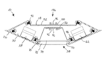
- FIG. 1 is an upper perspective view of a portion of a light fixture.
- FIG. 2 is an upper perspective view of the portion of the light fixture of FIG. 1 , shown with a dust cover removed.
- FIG. 3 is a lower perspective view of the portion of the light fixture of FIG. 1 .
- FIG. 4 is a lower perspective view of the portion of the light fixture of FIG. 1 , shown with a dust cover and an end cap flange removed.
- FIG. 5 is a cross-sectional view of the light fixture of FIG. 1 through line 5 - 5 in FIG. 1 .
- FIG. 6 is a cross-sectional view of the light fixture in accordance with another embodiment.
- FIG. 7 is an upper perspective view of a portion of a light fixture in accordance with another embodiment.
- FIG. 8 is a cross-sectional view of the light fixture of FIG. 7 through line 8 - 8 in FIG. 7 .
- FIG. 9 is a lower perspective view of a portion of a light fixture in accordance with another embodiment.
- FIG. 10 is a side view of the light fixture of FIG. 9 including wall mounting brackets.
- FIG. 11 is a side view of the light fixture of FIG. 9 including pendants for ceiling mounting.
- FIG. 12 is a side view of the light fixture of FIG. 9 including multiple housing sections aligned end-to-end.
- FIG. 13 illustrates a low peak angle light distribution for indirect lighting in accordance with one or more embodiments.
- FIG. 14 illustrates a standard light distribution for indirect lighting in accordance with one or more embodiments.
- FIG. 15 illustrates a light distribution for direct lighting in accordance with one or more embodiments.
- FIG. 16 illustrates a method for optimizing a programmable light fixture.
- FIGS. 1-8 illustrate several programmable luminaires or light fixtures 10 according to one or more embodiments of the application.
- an indirect/direct (I/D) programmable luminaire is shown that emits light in a first direction (e.g., an upward direction) from the light fixture 10 and also emits light from the light fixture in a second direction opposite the first direction (e.g., a downward direction).
- the light fixture 10 includes at least one housing 14 having a longitudinal axis A.
- the housing 14 further has a first, upper channel portion 18 , a second, lower channel portion 22 , and side portions 26 extending along the axis A.
- the side portions 26 , the upper channel portion 18 , and the lower channel portion 22 define an interior space 30 .
- the side portions 26 each have upper and lower converging walls that generally define a sideways wedge or “V” shape.
- the housing further includes an end cap flange 34 at each distal end of the housing 14 .
- the housing 14 may be mounted to a wall (e.g., by wall mounting brackets— FIG. 10 ) or a ceiling (e.g., by pendants— FIGS. 11-12 ).
- the light fixture 10 further includes a first or indirect light assembly 36 having a pair of first or indirect light boards 40 and a second or direct light assembly 38 having a second or direct light board 42 .
- the indirect light assembly 36 may include fewer or more indirect light boards 40 and the direct light assembly 38 may include more than one direct light board 42 .
- the indirect light boards 40 and the direct light boards 42 each include a plurality of light emitting elements 46 , such as light emitting diodes (LEDs).
- the LEDs 46 generally emit light in a semi-spherical lambertian distribution.
- each of the indirect light boards 40 and the direct light board 42 is a generally continuous board, in which the LEDs 46 are generally spaced apart along a length of the light boards 40 , 42 , such that emitted light extends along the length of the light boards 40 , 42 .
- each of the indirect light boards 40 and direct light board 42 is made of a plurality of lights boards connected in series to extend the entire length of the light fixture 10 .
- the boards 40 , 42 may each be a single continuous board that extends the entire length of the light fixture 10 .
- each of the indirect light boards 40 and the direct light board 42 may be a breakable light board that includes multiple sections that are connected together by perforated or frangible connecting portions, such as described in U.S. application Ser. No. 15/097,946, filed Apr. 13, 2016, which is incorporated herein by reference.
- the light fixture 10 when the light fixture 10 is hung from a ceiling or mounted to a wall, the light fixture is generally oriented such that the LEDs 46 of the indirect light boards 40 of the indirect light assembly 36 emit light upwards toward a ceiling (i.e., indirect light output), and the LEDs 46 of the direct light boards 46 emit light downwards toward a floor (i.e., direct light output) from the direct light boards 46 .
- the indirect light assembly 36 of the light fixture 10 of FIGS. 1-5 is arranged in a low peak angle distribution configuration.
- the indirect light assembly 36 of the light fixture 10 further includes a reflector 50 that is positioned within the upper channel portion 18 and extends along the length of the housing 14 .
- a row of indirect light boards 40 is arranged on each side of the reflector 50 coupled to an indirect light board bracket 54 within the upper channel portion 18 and arranged to extend parallel to the longitudinal axis A of the housing 14 .
- the indirect light board brackets 54 are integral to the upper channel portion 18 .
- Each of rows of the indirect light boards 40 is in facing relation with one another and is oriented at an obtuse angle with a bottom surface 52 of the upper channel portion 18 so that each of the rows of indirect light boards 40 directs a beam at a low angle out of the upper channel portion 18 (e.g., in a slightly upward direction at the ceiling).
- some light is diffusely reflected by the reflector 50 and directed toward the ceiling to increase the efficacy.
- the indirect light output from the LEDs 46 of the indirect light boards 40 has a low peak angle light distribution ( FIG. 13 ).
- the indirect light boards 40 may be arranged in a different configuration to provide a different distribution based on, among other things, environmental considerations (i.e., ceiling height and fixture spacing) and desired lighting conditions.
- the direct light assembly 38 of the light fixture 10 of FIGS. 1-5 is arranged in a high efficacy distribution configuration.
- the direct light board 42 is coupled longitudinally along a lower surface 56 of the lower channel portion 22 and extends parallel to the longitudinal axis A.
- the direct light board 42 includes three parallel rows of LEDs 46 .
- the direct light board 42 emits light away from the indirect light board (e.g., downwardly). In some embodiments, the direct light board 42 emits light out of the lower channel portion 22 and towards the floor. Side walls of the lower channel portion 22 include reflective surfaces to concentrate and increase the efficacy of the direct light output from the LEDs 46 of the direct light board 42 .
- the direct light output from the LEDs 46 of the direct light board has a high efficacy distribution ( FIG. 15 ).
- the direct light boards 42 may be arranged in other configurations to provide a different distribution based on, among other things, environmental considerations (i.e., ceiling height and fixture spacing) and desired lighting conditions.
- the light fixture 10 further includes a first or indirect light driver 58 and a second or direct light driver 62 that are positioned within the interior 30 of the housing 14 and supported by the side portions 26 .
- the indirect light driver 58 is in electrical communication with the indirect light boards 40 .
- the direct light driver 54 is in electrical communication with the direct light boards 42 .
- the indirect light driver 58 independently controls the indirect light boards 40
- the direct light driver 62 independently controls the direct light board 42 , respectively.
- the indirect light driver 58 and the direct light driver 62 can control an intensity of the indirect light output of the indirect light board 40 and an intensity of the direct light output of the direct light board 42 by varying voltage to provide various power levels to the light boards 40 , 42 .
- the indirect light driver 58 and the direct light driver 62 are configurable drivers, each having at least a first configuration and a second configuration.
- the indirect light driver 58 is programmed to a first configuration and the direct light driver 62 is programmed to a second configuration.
- the second configuration provides higher current output than the first configuration or vice versa.
- the indirect light driver 58 and direct light driver 62 are the same type or model of configurable driver.
- each of the drivers 58 , 62 is an OSRAIVI OT50 driver.
- the indirect light drivers 58 and the direct light drivers 62 may be any suitable LED driver, including a constant DC current output driver or a constant voltage output driver. In one embodiment, the driver has dimming capability.
- the light fixture 10 further includes a diffuser lens 66 that is supported opposite the direct light board 42 in front of the lower channel portion 22 by lips 70 defined by each of the side portions 26 .
- the diffuser lens 66 extends along the length of the housing 14 .
- the diffuser lens 66 scatters the direct light output from the LEDs 46 of the direct light boards 46 exiting the lower channel portion 22 to create soft lighting conditions.
- the diffuser lens 66 may simply be a transparent lens and may be made of acrylic, glass, or another suitable material. In other embodiments (e.g., FIG.
- the diffuser lens 66 may be substituted with a combination of a baffle 72 with a lens overlay 74 to further diffuse the light emitted by the LEDs 46 of the direct light boards 42 .
- the light fixture may not include any lens.
- the light fixture 10 further includes a dust cover 76 that is supported by at least one pair of dust cover support brackets 78 within the upper channel portion 18 .
- the dust cover 76 extends along the length of the housing 14 and is spaced from a bottom surface 52 of the upper channel portion 18 by the dust cover support brackets 78 .
- the dust cover 76 is positioned over the indirect light boards 40 to inhibit dust and other foreign matter from accumulating on the indirect light boards 40 and corresponding LEDs 46 .
- the dust cover 76 may be transparent or translucent, and may act as a diffuser so as to “soften” the indirect light output from the LEDs 46 of the indirect light boards 40 .
- the light fixture 10 may not include the dust cover 76 , as shown in FIG. 2 .
- the light fixture 10 i.e., the boards 40 , 42 and the drivers 58 , 62
- the light fixture 10 is electrically connected to an AC power source (e.g., mains) by a power cord.
- an AC power source e.g., mains
- a battery may be used to provide power to the lighting fixture 10 .
- the lighting fixture 10 may further include a daylight photosensor 82 .
- the photosensor 82 is positioned within the lower channel portion 22 and is supported by the lips 70 adjacent the diffuser lens 66 , and is oriented to face downwardly from the light fixture 10 .
- the photosensor 82 may be positioned anywhere on the light fixture 10 and in any orientation that facilitates sensing of ambient light.
- the photosensor 82 receives power from a power pack 84 located within the interior 30 of the housing 14 and supported by a power pack bracket 86 .
- the power pack 84 may receive power from the mains.
- the photosensor 82 may be electrically connected to one or both of the indirect light and direct light drivers 58 , 62 to control one or both of the indirect light boards 40 and the direct light boards 42 .
- the photosensor 82 is operable to sense ambient light (i.e., daylight) levels and control the intensity of the light emitted by the LEDs 46 of one or both of the indirect light boards 40 and the direct light boards 42 , accordingly. In one embodiment this is done by sending a signal from photosensor 82 to the drivers 58 , 62 to increase or decrease the respective intensity.
- the photosensor 82 detects a level of ambient light above a predefined threshold, the LEDs 46 are dimmed by the drivers 58 , 62 ; if a relatively lower amount of ambient light is detected, the intensity of light emitted by the LEDs 46 is increased.
- the photosensor 82 is connected directly to the indirect light and direct light boards 40 , 42 for controlling the intensity of the LED modules. The daylight photosensor 82 further increases the efficiency of the light fixture 10 .
- FIGS. 7-8 illustrate another embodiment of the light fixture 10 including an indirect light assembly 136 arranged in a second, standard distribution configuration, in which a single row of indirect light boards 140 may be positioned longitudinally along a bottom surface 152 of a upper channel portion 118 parallel to the longitudinal axis A of the housing 14 .
- the indirect light boards 140 are oriented such that the indirect light output emitted by the LEDs 46 is directed upwardly out of the upper channel portion 118 along a vertical axis perpendicular with the bottom surface 152 of the upper channel portion 118 .
- the indirect light output emitted by the indirect light boards 40 has a standard (lambertian) distribution as shown in the graph in FIG. 14 .
- the light fixture 10 illustrates aspects of knife-type light fixtures.
- the light fixture 10 may be a rail-type light fixture 210 .
- the knife-type light fixture 10 and the rail-type fixture 210 provide a range of light outputs, light distribution patterns, and fixture designs. The primary difference being the shape of the housing 214 and in particular the shape of the side portions 226 , which have a rectangular channel shape.
- the boards 40 , 42 , the drivers 58 , 62 , and other features described above with respect to the knife-type light fixture may be incorporated into the rail-type light fixture 210 embodiment of FIGS. 9-12 , and vice versa.
- the housing 214 of the light fixture 210 may be mounted to a wall by brackets 90 .
- the light fixture 210 may be suspended from a ceiling by pendants 94 , as shown in FIG. 11-12 .
- the light fixture 210 may be mounted to a wall or a ceiling in another suitable manner.
- the light fixture 210 may also be supported by an independent or freestanding structure.
- the knife-type light fixtures 10 of FIGS. 1-8 may also be supported by the brackets 90 or the pendants 94 .
- the housing 214 of the light fixture 210 may be made of multiple sections 98 .
- each of the sections 98 has a length of approximately 4 feet.
- each section 98 may be approximately 3 feet long, approximately 6 feet long, approximately 8 feet long, or any other suitable length.
- the multiple sections 98 may be connected together, e.g., via dowels and/or fasteners.
- the drivers 58 , 62 and boards 40 , 42 of each section 98 may be electrically connected together so that only one power source is required to power the light boards 40 , 42 of the sections 98 of the light fixture 10 .
- the diffuser lenses 66 of each section directly abut each other end-to-end to provide a seamless appearance and continuous linear light along the length of the housing 14 .
- the dust covers 76 of each section may directly abut one another end-to-end along the length the housing 14 .
- FIG. 7 illustrates the rail-type light fixture 210
- the knife-type light fixture 10 of FIGS. 1-8 may also be made of multiple sections.
- the indirect light assembly 136 and the direct light assembly 38 may be independently arranged in different configurations to produce different light distribution patterns for optimizing the light output for various environmental conditions.
- the indirect light assembly 136 of the light fixture 10 is arranged in the standard distribution configuration so that the indirect light output has a standard light distribution as shown in the graph in FIG. 14 .
- the LEDs 46 of the single row of indirect light boards 140 emit light in a generally lambertian distribution directly toward the ceiling, such that the indirect light output covers a relatively narrow surface area above the light fixture 10 .
- reflectors or optics may be provided to narrow the indirect light output.
- the indirect light assembly 36 of the light fixture 10 is arranged in the low peak angle distribution configuration so that the indirect light output has a low peak angle light distribution as shown in the graph in FIG. 13 .
- the LEDs 46 of each of the rows of indirect light boards 40 emit light at a low angle toward the ceiling, such that the indirect light output has two peak intensities that are spaced by an angle of approximately 112.5 degrees, thereby covering a wider surface area while having a shallower depth (i.e., a lower efficacy range) than the standard distribution.
- the rows of the indirect light boards 40 may be arranged at different angles, such that peak intensities are spaced by a larger or smaller angle. Some of the direct light output emitted by each of the rows of indirect light boards 40 diffusely reflects off the reflector 50 to further distribute the light and increase the efficacy.
- the standard light distribution may be more suitable for higher ceilings (e.g., 16 feet high or more), while the low peak angle option may be more suitable for lower ceilings (e.g., 8 feet high).
- the direct light assembly 38 is arranged, independent of the indirect light assembly 36 , in a high efficacy distribution configuration so that the direct light output has a high efficacy distribution as shown in the graph in FIG. 15 .
- the LEDs 46 of the direct light boards 42 emit light toward the floor in a generally lambertian distribution. The light is reflected by the sidewalls of the lower channel portion 22 to narrow the direct light output. Accordingly, the direct light distribution pattern has a higher efficacy than the indirect light output of both configurations of the exemplary indirect light assembly 36 , 136 .
- the direct light assembly 38 may be configured similar to the indirect light assembly 36 in the low peak angle distribution configuration ( FIGS. 2 and 5 ) or the standard distribution configuration ( FIGS. 7-8 ) so that the direct light output has a similar low peak angle light distribution or standard light distribution, or any other desirable distribution configuration.
- the direct light boards 42 and indirect light boards 40 are easily removable and replaceable from the light fixture 10 while installed.
- the indirect light boards 40 are supported on the upper channel portion 18 , and the upper channel portion 18 is removably coupled to the side portions 26 , e.g., by fasteners 92 ( FIGS. 2-3 ).
- the indirect light boards 40 can be removed and replaced by uncoupling the upper channel portion 18 from the side portions 26 .
- the direct light boards 42 are supported on the lower channel portion 22 that is coupled to the side portions 26 , e.g., by fasteners 96 .
- the direct light boards 42 can be removed and replaced by uncoupling the lower channel portion 22 from the side portions 26 .
- the configuration of the indirect light assembly 36 and the direct light assembly 38 may be simply changed by removing and replacing the upper channel portion 18 and the lower channel portion 22 , respectively.
- the upper channel portion 18 supporting the indirect light assembly 36 in the first, low peak angle distribution configuration ( FIGS. 2 and 5 ) may be removed and replaced with an upper channel portion 118 supporting the indirect light assembly 136 in the second, standard distribution configuration ( FIGS. 7-8 ).
- the indirect light driver 58 and the direct light driver 62 are independently programmed to provide control over the light output of the indirect light boards 40 and the direct light boards 42 , respectively.
- intensity may be independently specified for the light output of the direct light boards 42 , and the same or a different intensity may be specified for the light output of the indirect light boards 40 .
- the independent control of the boards 40 , 42 allows an operator to optimize performance of the light fixture 10 depending on environmental conditions, such as ceiling height and desired illuminance.
- a light intensity (i.e., illuminance) of the light output by the indirect light boards 40 or the direct light boards 42 is variable in increments of approximately 100 lumens per four feet (lm/4 ft).
- the light intensity may be variable in increments of approximately 50 lm/ft. In some embodiments, the light intensity is variable between a minimum of approximately 1000 lm/4 ft to a maximum of approximately 4000 lm/4 ft (250-1000 lm/ft).
- the intensity of the direct light output by the direct light boards 42 may be variable between a minimum of approximately 600 lm/4 ft and a maximum of approximately 3500 lm/4 ft (150-875 lm/ft).
- independently specifying the light distribution pattern of the indirect and direct light output allows for further optimization, as well as maximum fixture efficacy.
- controlling the power transmitted to the fixture 10 to satisfy power density requirements increases energy efficiency.
- the drivers 58 , 62 may be programmed so that 70% of the power goes to the indirect light boards 40 , while 30% of the power goes to the direct light boards 42 .
- the indirect light driver 58 and the direct light driver 62 are configurable drivers, each having at least a first and a second configuration.
- the indirect light driver 58 is programmed to a first configuration (e.g., providing 70% of full power) and the direct light driver 62 is programmed to a second configuration (e.g., providing 30% of full power).
- the indirect and direct light drivers 58 , 62 if at full power could exceed a predetermined maximum allowable power level (e.g., a maximum power rating for the fixture 10 , or a maximum power level established by regulation such as an energy code). However, at least one of the indirect light driver 58 and the direct light driver 62 are configured to provide less than their full power rating such that the combined configured maximum power of the two drivers does not exceed the predetermined power level. In some embodiments, the indirect and direct light drivers 58 , 62 are configured at a source such as a manufacturer or integrator or by an authorized installation technician.
- the indirect light driver 58 and the direct light driver 62 allow for independent dimming of the light output of the indirect light boards 40 and the direct light boards 42 .
- a standard 0-10V driver provides a dimming range between 100% and 10%.
- a driver may provide a dimming range between 100% and 5%.
- the dimming range may be between 100% and 1%, or between 100% and 0%.
- the drivers 58 , 62 may be configured with the light boards 40 , 42 for simultaneous dimming.
- a color temperature of the LEDs 46 of the light boards 40 , 42 is determined based on a temperature LED chip (not shown) coupled to the light boards 40 , 42 (the color temperature of the LEDs 46 of the direct light board 42 is determined in a similar manner by a temperature chip on the direct light boards 42 ).
- the color temperature may be approximately 30K, 35K or 40K.
- the color temperature of the indirect light boards 40 and/or the direct light boards 42 may be varied by populating each of the light boards 40 , 42 with various color temperature chips and adjusting the drive current to each chip.
- the color temperature may be varied (e.g., by a dimmer/mixer) by adjusting a drive current to separate color temperature boards.
- the light fixture 10 is configured to have an end-of-life indicator feature. After one of the indirect light driver 58 and the direct light driver 62 reaches its programmed life-time, whenever the light fixture 10 is powered on. The one of the indirect light driver 58 and the direct light driver 62 that has reached its programmed life-time will stay at a “dim” level, in which intensity of a corresponding one of the indirect light output and the direct light output is decreased to 10% of its maximum for a predetermined amount of time (e.g., approximately 10 minutes) before slowly reaching its maximum power level. This serves to indicate to a user that the one of the indirect light driver 58 and the direct light driver 62 needs to be replaced soon.
- a predetermined amount of time e.g. 10 minutes
- FIG. 16 illustrates a method 1000 for optimizing the light fixture 10 is provided.
- required light output i.e., both indirect and direct light output
- the environmental conditions and considerations may include, for example illumination area (i.e., area to be illuminated above and below light fixture 10 ), fixture spacing (i.e., spaced between adjacent light fixtures), and ceiling height.
- a configuration of the indirect light assembly 36 is selected for the light fixture 10 based on a specified indirect light distribution for the indirect light output.
- the specified indirect light distribution may be driven by the required output for the specified environmental conditions.
- the configuration may be selected from a plurality of configurations including the standard distribution configuration and the low peak angle distribution configuration.
- the low peak angle distribution configuration may be selected for low ceiling heights and/or wide fixture spacing.
- the standard distribution configuration may be selected for high ceiling heights and/or narrow fixture spacing.
- a configuration of the direct light assembly 38 is selected for the light fixture 10 based on a specified direct light distribution for the direct light output.
- the specified direct light distribution may be determined by the required direct light output for the specified environmental conditions. In the illustrated embodiment, the high efficacy distribution configuration is shown.
- an intensity of the indirect light output of the indirect light boards 40 of the indirect light assembly 36 is set by programming the indirect light driver 58 to control and provide power to the indirect light boards 40 to provide an intensity of the indirect light output.
- an intensity of the direct light output of the direct light boards 42 of the direct light assembly 38 is set by programming the direct light driver 62 to control power to the direct light boards 42 to provide a specified intensity for the direct light output.
- the intensity of each of the indirect light output and the direct light output may be increased or decreased independently for various reasons, such as to meet the desired illuminance for the environmental conditions and considerations. For example, the intensity of the indirect light output may be increased for high ceiling heights and decreased for low ceiling heights.
- the power from the indirect light driver 58 and the direct light driver 62 in combination cannot exceed a maximum allowable power level.
- the light fixture 10 is assembled based on the selected configurations for the indirect light assembly 36 and the direct light assembly 42 , and the specified intensities for the indirect light output and the direct light output. This may include programming the indirect and direct light drivers 58 , 62 to control the power to the indirect and direct light boards 40 , 42 respectively. This may also include configuring the indirect and direct light assemblies 36 , 38 in the specified configurations.
- the light fixtures 10 may be spaced farther apart than if the indirect light assembly 136 is selected to be configured in the standard distribution configuration while still providing the same illuminance. That is, the same illuminance can be obtained while using fewer light fixtures. Decreasing the number of light fixtures results in less overall cost.
- the indirect light assembly 36 is arranged in the low peak angle distribution configuration for multiple light fixtures 10 in an exemplary space.
- the indirect light driver 58 and the direct light driver 62 By independently programming the indirect light driver 58 and the direct light driver 62 to increase the intensity of the indirect light output and decrease intensity of the direct light output, similar performance may be achieved using one less light fixture. Decreasing the number of light fixtures results in less overall cost.
- the light fixture includes indirect light and direct light LED boards that are independently controlled by programmable indirect light and direct light drivers and independently configured in different configurations to independently vary indirect and direct light output characteristics, such as light intensity and distribution pattern.
Abstract
Description
Claims (21)
Priority Applications (3)
| Application Number | Priority Date | Filing Date | Title |
|---|---|---|---|
| US15/142,599 US10088117B2 (en) | 2015-05-01 | 2016-04-29 | Luminaire with independently controlled light output |
| US16/148,549 US10502376B2 (en) | 2015-05-01 | 2018-10-01 | Luminaire with independently controlled light output |
| US16/707,664 US10941909B2 (en) | 2015-05-01 | 2019-12-09 | Luminaire with independently controlled light output |
Applications Claiming Priority (2)
| Application Number | Priority Date | Filing Date | Title |
|---|---|---|---|
| US201562156064P | 2015-05-01 | 2015-05-01 | |
| US15/142,599 US10088117B2 (en) | 2015-05-01 | 2016-04-29 | Luminaire with independently controlled light output |
Related Child Applications (2)
| Application Number | Title | Priority Date | Filing Date |
|---|---|---|---|
| US16/148,549 Continuation US10502376B2 (en) | 2015-05-01 | 2018-10-01 | Luminaire with independently controlled light output |
| US16/148,549 Continuation-In-Part US10502376B2 (en) | 2015-05-01 | 2018-10-01 | Luminaire with independently controlled light output |
Publications (2)
| Publication Number | Publication Date |
|---|---|
| US20160323950A1 US20160323950A1 (en) | 2016-11-03 |
| US10088117B2 true US10088117B2 (en) | 2018-10-02 |
Family
ID=57205481
Family Applications (1)
| Application Number | Title | Priority Date | Filing Date |
|---|---|---|---|
| US15/142,599 Active US10088117B2 (en) | 2015-05-01 | 2016-04-29 | Luminaire with independently controlled light output |
Country Status (4)
| Country | Link |
|---|---|
| US (1) | US10088117B2 (en) |
| CA (1) | CA2983117C (en) |
| MX (2) | MX2017013966A (en) |
| WO (1) | WO2016178992A1 (en) |
Families Citing this family (2)
| Publication number | Priority date | Publication date | Assignee | Title |
|---|---|---|---|---|
| US10514133B2 (en) | 2017-11-28 | 2019-12-24 | Contemporary Visions, LLC | Lighting system |
| CN113424661B (en) | 2019-02-21 | 2024-03-22 | 昕诺飞控股有限公司 | Lighting system with constant illuminance dimming |
Citations (10)
| Publication number | Priority date | Publication date | Assignee | Title |
|---|---|---|---|---|
| US20050231133A1 (en) * | 2004-03-15 | 2005-10-20 | Color Kinetics Incorporated | LED power control methods and apparatus |
| US20090079357A1 (en) * | 2007-09-21 | 2009-03-26 | Exclara Inc. | Regulation of Wavelength Shift and Perceived Color of Solid State Lighting with Intensity Variation |
| US20110178977A1 (en) * | 2009-06-22 | 2011-07-21 | Johnson Controls Technology Company | Building management system with fault analysis |
| US20120020092A1 (en) * | 2011-04-25 | 2012-01-26 | Bailey Edward E | Multiple-tier Omnidirectional Solid-State Emission Source |
| US20130093325A1 (en) * | 2011-10-17 | 2013-04-18 | Eco Lumens, Llc | Light emitting diode (led) lighting systems and methods |
| US20130107527A1 (en) * | 2011-11-01 | 2013-05-02 | Lsi Industries, Inc. | Luminaires and lighting structures |
| US20130188347A1 (en) | 2012-01-22 | 2013-07-25 | Ecolivegreen Corp. | LED Light Fixture |
| US20140168287A1 (en) | 2008-09-30 | 2014-06-19 | Dolby Laboratories Licensing Corporation | Power Management for Modulated Backlights |
| US20140293603A1 (en) * | 2013-03-27 | 2014-10-02 | Sensity Systems, Inc. | Led light bulb replacement with adjustable light distribution |
| US9423113B2 (en) * | 2011-05-17 | 2016-08-23 | Pixi Lighting, Inc. | Flat panel lighting device and driving circuitry |
-
2016
- 2016-04-29 US US15/142,599 patent/US10088117B2/en active Active
- 2016-04-29 WO PCT/US2016/030096 patent/WO2016178992A1/en active Application Filing
- 2016-04-29 MX MX2017013966A patent/MX2017013966A/en active IP Right Grant
- 2016-04-29 MX MX2020001439A patent/MX2020001439A/en unknown
- 2016-04-29 CA CA2983117A patent/CA2983117C/en active Active
Patent Citations (10)
| Publication number | Priority date | Publication date | Assignee | Title |
|---|---|---|---|---|
| US20050231133A1 (en) * | 2004-03-15 | 2005-10-20 | Color Kinetics Incorporated | LED power control methods and apparatus |
| US20090079357A1 (en) * | 2007-09-21 | 2009-03-26 | Exclara Inc. | Regulation of Wavelength Shift and Perceived Color of Solid State Lighting with Intensity Variation |
| US20140168287A1 (en) | 2008-09-30 | 2014-06-19 | Dolby Laboratories Licensing Corporation | Power Management for Modulated Backlights |
| US20110178977A1 (en) * | 2009-06-22 | 2011-07-21 | Johnson Controls Technology Company | Building management system with fault analysis |
| US20120020092A1 (en) * | 2011-04-25 | 2012-01-26 | Bailey Edward E | Multiple-tier Omnidirectional Solid-State Emission Source |
| US9423113B2 (en) * | 2011-05-17 | 2016-08-23 | Pixi Lighting, Inc. | Flat panel lighting device and driving circuitry |
| US20130093325A1 (en) * | 2011-10-17 | 2013-04-18 | Eco Lumens, Llc | Light emitting diode (led) lighting systems and methods |
| US20130107527A1 (en) * | 2011-11-01 | 2013-05-02 | Lsi Industries, Inc. | Luminaires and lighting structures |
| US20130188347A1 (en) | 2012-01-22 | 2013-07-25 | Ecolivegreen Corp. | LED Light Fixture |
| US20140293603A1 (en) * | 2013-03-27 | 2014-10-02 | Sensity Systems, Inc. | Led light bulb replacement with adjustable light distribution |
Non-Patent Citations (1)
| Title |
|---|
| PCT/US2016/030096 International Search Report and Written Opinion dated Aug. 25, 2016 (15 pages). |
Also Published As
| Publication number | Publication date |
|---|---|
| MX2017013966A (en) | 2018-01-16 |
| CA2983117A1 (en) | 2016-11-10 |
| MX2020001439A (en) | 2021-01-25 |
| WO2016178992A1 (en) | 2016-11-10 |
| CA2983117C (en) | 2021-12-21 |
| US20160323950A1 (en) | 2016-11-03 |
Similar Documents
| Publication | Publication Date | Title |
|---|---|---|
| US10941909B2 (en) | Luminaire with independently controlled light output | |
| US9212808B2 (en) | LED lighting fixture | |
| US9829190B2 (en) | LED lamp apparatus and method of making an LED lamp apparatus | |
| US11480326B2 (en) | LED lighting fixture | |
| US7641361B2 (en) | Light emitting diode lamp | |
| EP2330345A2 (en) | Led lighting device | |
| US20110156584A1 (en) | Led lighting device | |
| US10794572B2 (en) | LED troffer fixture having a wide lens | |
| JP2011513913A (en) | LED lighting device | |
| US10830401B2 (en) | Medical examination light fixture | |
| US9756709B2 (en) | Wirelessly controlled lighting device | |
| TWI633255B (en) | Lighting system and lighting method | |
| US10088117B2 (en) | Luminaire with independently controlled light output | |
| CA2982248A1 (en) | Luminaire | |
| KR101347718B1 (en) | Illumination system capable of adjusting color temperature, hue and brightness | |
| KR20210002234A (en) | Integrated LED lighting system with longer life | |
| KR20050027190A (en) | Illumination lamp and control method using led | |
| US20100110658A1 (en) | Semi-direct solid state lighting fixture and distribution | |
| KR100970110B1 (en) | A led illuminator integral with lamp mount | |
| JP6288693B2 (en) | Lighting fixture and lighting device | |
| KR101141036B1 (en) | LED Lighting Fixture | |
| AU2012101534B4 (en) | A compact luminaire | |
| JP2020161245A (en) | Reflector and lighting device | |
| KR20130094609A (en) | Apparatus for controlling led light for a poultry farm | |
| MX2011002018A (en) | Led lighting device. |
Legal Events
| Date | Code | Title | Description |
|---|---|---|---|
| AS | Assignment |
Owner name: HUBBELL INCORPORATED, CONNECTICUT Free format text: ASSIGNMENT OF ASSIGNORS INTEREST;ASSIGNORS:OGG, JEREMY W.;BAKER, DEREK B.;CENTAZZO, MICHAEL J.;AND OTHERS;REEL/FRAME:038844/0321 Effective date: 20160608 |
|
| STCF | Information on status: patent grant |
Free format text: PATENTED CASE |
|
| MAFP | Maintenance fee payment |
Free format text: PAYMENT OF MAINTENANCE FEE, 4TH YEAR, LARGE ENTITY (ORIGINAL EVENT CODE: M1551); ENTITY STATUS OF PATENT OWNER: LARGE ENTITY Year of fee payment: 4 |
|
| AS | Assignment |
Owner name: HUBBELL LIGHTING, INC., CONNECTICUT Free format text: NUNC PRO TUNC ASSIGNMENT;ASSIGNOR:HUBBELL INCORPORATED;REEL/FRAME:058838/0162 Effective date: 20220112 |
|
| AS | Assignment |
Owner name: ALLY BANK, AS COLLATERAL AGENT, NEW YORK Free format text: SECURITY AGREEMENT;ASSIGNORS:HUBBELL LIGHTING, INC.;LITECONTROL CORPORATION;CURRENT LIGHTING SOLUTIONS, LLC;AND OTHERS;REEL/FRAME:058982/0844 Effective date: 20220201 |
|
| AS | Assignment |
Owner name: ATLANTIC PARK STRATEGIC CAPITAL FUND, L.P., AS COLLATERAL AGENT, NEW YORK Free format text: SECURITY INTEREST;ASSIGNORS:HUBBELL LIGHTING, INC.;LITECONTROL CORPORATION;CURRENT LIGHTING SOLUTIONS, LLC;AND OTHERS;REEL/FRAME:059034/0469 Effective date: 20220201 |
|
| AS | Assignment |
Owner name: ALLY BANK, AS COLLATERAL AGENT, NEW YORK Free format text: CORRECTIVE ASSIGNMENT TO CORRECT THE PATENT NUMBER 10841994 TO PATENT NUMBER 11570872 PREVIOUSLY RECORDED ON REEL 058982 FRAME 0844. ASSIGNOR(S) HEREBY CONFIRMS THE SECURITY AGREEMENT;ASSIGNORS:HUBBELL LIGHTING, INC.;LITECONTROL CORPORATION;CURRENT LIGHTING SOLUTIONS, LLC;AND OTHERS;REEL/FRAME:066355/0455 Effective date: 20220201 |
|
| AS | Assignment |
Owner name: ATLANTIC PARK STRATEGIC CAPITAL FUND, L.P., AS COLLATERAL AGENT, NEW YORK Free format text: CORRECTIVE ASSIGNMENT TO CORRECT THE PATENT NUMBER PREVIOUSLY RECORDED AT REEL: 059034 FRAME: 0469. ASSIGNOR(S) HEREBY CONFIRMS THE SECURITY INTEREST;ASSIGNORS:HUBBELL LIGHTING, INC.;LITECONTROL CORPORATION;CURRENT LIGHTING SOLUTIONS, LLC;AND OTHERS;REEL/FRAME:066372/0590 Effective date: 20220201 |