US1008707A - Radiator. - Google Patents
Radiator. Download PDFInfo
- Publication number
- US1008707A US1008707A US58070610A US1910580706A US1008707A US 1008707 A US1008707 A US 1008707A US 58070610 A US58070610 A US 58070610A US 1910580706 A US1910580706 A US 1910580706A US 1008707 A US1008707 A US 1008707A
- Authority
- US
- United States
- Prior art keywords
- radiator
- units
- unit
- air
- lower ends
- Prior art date
- Legal status (The legal status is an assumption and is not a legal conclusion. Google has not performed a legal analysis and makes no representation as to the accuracy of the status listed.)
- Expired - Lifetime
Links
- 210000003739 neck Anatomy 0.000 description 21
- 230000001174 ascending effect Effects 0.000 description 5
- 230000005855 radiation Effects 0.000 description 5
- 239000011324 bead Substances 0.000 description 4
- 238000010438 heat treatment Methods 0.000 description 4
- 239000002184 metal Substances 0.000 description 3
- 206010022000 influenza Diseases 0.000 description 2
- 238000010276 construction Methods 0.000 description 1
- 238000000034 method Methods 0.000 description 1
- 230000008520 organization Effects 0.000 description 1
- 230000000630 rising effect Effects 0.000 description 1
- 238000007493 shaping process Methods 0.000 description 1
Images
Classifications
-
- F—MECHANICAL ENGINEERING; LIGHTING; HEATING; WEAPONS; BLASTING
- F28—HEAT EXCHANGE IN GENERAL
- F28D—HEAT-EXCHANGE APPARATUS, NOT PROVIDED FOR IN ANOTHER SUBCLASS, IN WHICH THE HEAT-EXCHANGE MEDIA DO NOT COME INTO DIRECT CONTACT
- F28D1/00—Heat-exchange apparatus having stationary conduit assemblies for one heat-exchange medium only, the media being in contact with different sides of the conduit wall, in which the other heat-exchange medium is a large body of fluid, e.g. domestic or motor car radiators
- F28D1/02—Heat-exchange apparatus having stationary conduit assemblies for one heat-exchange medium only, the media being in contact with different sides of the conduit wall, in which the other heat-exchange medium is a large body of fluid, e.g. domestic or motor car radiators with heat-exchange conduits immersed in the body of fluid
- F28D1/04—Heat-exchange apparatus having stationary conduit assemblies for one heat-exchange medium only, the media being in contact with different sides of the conduit wall, in which the other heat-exchange medium is a large body of fluid, e.g. domestic or motor car radiators with heat-exchange conduits immersed in the body of fluid with tubular conduits
- F28D1/053—Heat-exchange apparatus having stationary conduit assemblies for one heat-exchange medium only, the media being in contact with different sides of the conduit wall, in which the other heat-exchange medium is a large body of fluid, e.g. domestic or motor car radiators with heat-exchange conduits immersed in the body of fluid with tubular conduits the conduits being straight
- F28D1/05308—Assemblies of conduits connected side by side or with individual headers, e.g. section type radiators
-
- F—MECHANICAL ENGINEERING; LIGHTING; HEATING; WEAPONS; BLASTING
- F28—HEAT EXCHANGE IN GENERAL
- F28D—HEAT-EXCHANGE APPARATUS, NOT PROVIDED FOR IN ANOTHER SUBCLASS, IN WHICH THE HEAT-EXCHANGE MEDIA DO NOT COME INTO DIRECT CONTACT
- F28D21/00—Heat-exchange apparatus not covered by any of the groups F28D1/00 - F28D20/00
- F28D2021/0019—Other heat exchangers for particular applications; Heat exchange systems not otherwise provided for
- F28D2021/0035—Other heat exchangers for particular applications; Heat exchange systems not otherwise provided for for domestic or space heating, e.g. heating radiators
Definitions
- Our invention consists of an apparatus for radiating the heat of heated air from a furnace or similar air-heater.
- It further consists of an apparatus for radiating such heat and returning the air to the furnace to again be heated after it has given olf its heat in the radiator.
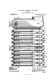
- Figure l represents a vertical section through our improved radiator.
- Fig. 2 represents a vertical section, in a plane at right angles to that of Fig. 1, of one of the radiator units.
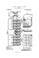
- Fig. 3 represents a horizontal section of the radiator and wall boxes.
- Fig. 4 represents a face view of a wall box.
- Fig. 5 represents a view of the lower end of one of the units.
- Fig. 6 represents -a vertical section of the lower end of a radiator unit and a wall box.
- Fig. 7 represents perspective views of parts of the joint between the radiator units.
- Fig. 8 represents a perspective detail view of a portion of the front of a wall box.
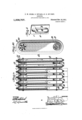
- Fig. 9 represents a vertical section of a form of radiator constructed to allow the air to discharge into the Surrounding air.
- Fig. l0 represents an elevation of the last unit of said form of apparatus, showing the register opening in the same.
- the radiator is composed of units l, made from sheet metal and each consisting of two halves, preferably from stampedk or otherwise shaped metal sheets, having interlocking beaded edges.
- the edges of one half are formed with a bead 2, semicircular in cross section, and the edges of the other half are formed with a bead 3, circular in cross section, which latter bead encircles the semicircular bead, and thus forms a rm and tight joint at the seams uniting the halves of each unit.
- each unit is deep and narrow and oblong in cross section, and at the lower ends they are formed with necks 4, projecting from one edge of each unit, and also oblong in cross section.v Near its upper end, each unit, excepting the terminal or end units of each set, has a laterally projecting neck 5, on each flatside, and one of said ynecks has an inturned flange 6, formed with an annular groove 7 in its face, which preferably 1s interrupted to form an annular series of segmental grooves.
- the opposite yneck of the adjacent section has a corresponding annular rib 8 upon its face, which is also preferably interruptedv to form an annular series of segmental'ribs, registering with and engaging the-grooves of the opposed neck, said series of ribs and grooves vengaging to vinsure tight joints and perfect alinement of the units.
- the unit at the end of each set has only one of said necks, illustrat'ed in the drawings, as the neck having the annular grooves at one end-unit and the neck having the ribs at the other end unit.
- the necks, flanges and ribs and grooves are stamped or otherwise shaped from and integral with the unit-halves and so produced in the process of shaping the latter.
- a wall box or casing 9 is provided to communicate with the opening of a furnace flue (not shown), and said bo'x has a number of oblong openings 10, corresponding'in shape to that of the lower necks 4 of the units.
- Each opening has an outwardly projecting flange 11, surrounding the lower portion of the same, and an inwardly projecting liange l2, surrounding the upper portion of the opening, and said flanges close the joint between the neck of each unit and the opening into which it is fitted.
- the neck In fitting the neck of a section, the neck is placed from above into the lower flange and is then moved into the opening, where the flanges will thus close the joint and prevent lateral escape of hot air through the same.
- two intermediate or center units 13 similar to the outer units, but each having only one joint neck 5, at its upper end to connect it to the adjoining unit, and both being connected near their lower ends by necks 14, having annular interlocking groove and rib connections 15, like t-he joint necks 5.
- the lower ends of the two sets of units are spaced by collars 16, and the upper ends of the two center units are spaced by a collar 17.
- the units are all connected near their1 upper and lower ends by means of stay-rods 18 and 19.
- the wall boXes 9 form respectively a supply boX, and a return boX, being respectively connected to a flue conveying hot air from the furnace and a liuc conveying air back to the air chamber' of the furnace, (such flues not being shown), and each box has one set of units secured to it, four units being illustrated in the drawings as forming a set, one set for the ascending hot air, and one set for the descending cooled air.
- the ascending hot air passes up through the units and passes from the upper ends of the same through the connecting necks into the upper end of a center unit, through which it descends and passes into the second center unit and ascends through the same.
- the air passes through the connecting necks of the second set of radiator units and down through the latter to the wall boX and flue carrying the now cooled air back to the heating chamber of the furnace.
- the air passing up and down through the radiator gives off its heat through the units, which, on account of their deep and narrow shape, oifer an eX- tensive radiating surface while occupying comparatively small floor space.
- radiator heating is accomplished by radiation from the furnace heated air, without the latter entering the room, and thus impoverishing and vitiating the air in the saine, and the radiator maybe employed with any hot air furnace, it being only necessary to provide return iiues and connecting them with the bottom of the heating chamber of the furnace.
- Figs. 9 and 10 Conditions may arise when it is not practical or desirable to provide return flues, while it is desired to accomplish heating by radiation, and in such case the form illustrated in Figs. 9 and 10 is employed.
- the radiator units connected to the wall boX upon the return flue is dispensed with, and an annular series of register openings 20 is provided at the upper end of the unit carrying the ascending air, with an annular register plate 21, covering the same, so that the hot air, after having radiated heat in its passage through the radiator units, may be admitted to the room under control of the register.
- the heat from the furnace heated air is utilized by radiation.
- the air in the room is only heated by radiation, and in the form illustrated in Figs. 9 and 10, the air in the room is heated partly by radiation, and partly by direct admission of warm air.
- the heated air is retarded in its passage through the radiator so as to part with la considerable portion of its heat by rising in the ascent set of units, thereupon descending through the single descent unit, again ascending through the single ascent unit, and iinally descending through the descent set of units.
- the intermediate or center units serve as reversing units, reversing the ascending columns of hot air to descend the descent units.
- a set of ascent radiator units arranged side by side and having inlet at their lower ends, and connected at their upper 'ends to communicate with each other
- a set of descent radiator units arranged side by side and having outlet at their lower ends and connected at their upper ends to communicate with each other
- a pair of intermediate reversing units connected at their lower ends and respectively connected to the upper end of one unit of a set.
- a set of narrow and deep, vertical radiator ascent units arranged side by side and having inlet at their lower ends and connected at their upper ends to communicate with each other
- a set of narrow and deep, vertical radiator descent units arranged side by side and having outlets at their lower ends and connected at their upper ends to communicate with each other
- a pair of narrow and deep intermediate reversing units each connected at its upper end to the upper end'of one unit of a set and connected with each other at their lower ends.
- a set of vertical ascent radiator units arranged side by side and connected at their lower ends to the supply box and connected together at their upper ends to communicate with each other
- a set of vertical descent radiator units arranged side by side and connected at their lower ends to the return box and connected together at their upper ends to communicate with each other
- a pair of intermediate reversing units connected at their upper ends, each to one set of units to communicate with the same, and at their lower ends to communicate with each other.
- a wall box having an oblong opening formed with an outwardly projecting ange around the lower portion of its periphery, and an inwardly projecting iange around the upper portion of its periphery, and a radiator unit formed with a neck fitting into said opening and flanges.
- a supply wall box having oblong flanged openings in its face
- a return wall box having oblong anged openings in its face
- two sets of deep and narrow, vertical sheet metal radiator units formed with laterally extending necks, oblong in cross section and entering said openings, and the units of each set formed with ljoined necks at their upper ends connecting each set of unit-s, and a pair of deep and narrow, vertical reversing units connected by joined necks at their lower ends, and each connected at its upper end by a joined neck to the upper end of the adj oining'unit of one set.
Landscapes
- Engineering & Computer Science (AREA)
- Physics & Mathematics (AREA)
- Thermal Sciences (AREA)
- Mechanical Engineering (AREA)
- General Engineering & Computer Science (AREA)
- Heat-Exchange Devices With Radiators And Conduit Assemblies (AREA)
Description
P. W. DILKS, D. REYA'M & E. E. DU PONT.
RADIATOR. APPLICATION FILI-*ID SP'LG, 1910.
Patented Nov. 14,1911.
3 SHEETS-SHEET 1.
coLuMBIA PLANOGRAPN C0.. WASHINGTON. n. c.
glllllllll ATTRNEYs l F. W. DILKS, D. REYAM 6v E. E. DU PONT.
RADIATOR.
APPLICATION FILED SEPT. 6, 1910.
1,008,707. Patented Nov.14, 1911.
3 SHEETS-SHEET 2.
COLUMBIA PLANDGRAPH C0.. WASHINGTON. D. c.
P. W. DILKS, D. RBYAM & E. E. DU PONT.
RADIATOR.
APPLICATION FILED SBPT.6, 1910.
1,008,707. Patented Nov. 14,1911.
3 SHEETS-SHEET 3.
COLUMBIA PMNOGRAPH 50WASHINDTON. D. c,
UNTTED STATES PATENT OFFICE.
FRANK W. DILKS, OF PHILADELPHIA, PENNSYLVANIA, AND DAVID REYAM AND EUGENE E. DU PONT, OF WILMINGTON, DELAWARE, ASSIGNORS TO THE INTERNA- TIONAL RADIATOR COMPANY, OF WILMINGTON, DELAWARE, A'CORPORATION OF DELAWARE.
RADIATOR.
Specicaton of Letters Patent.
Patented Nov. 14, 1911.
Application led September 6, 1910. Serial No. 580,706.
To all whom it may concern:
Be it known that we, FRANK W. DrLKs,a citizen of the United States, residing in the city and county of Philadelphia, State of Pennsylvania, and DAVID REYAM and EUGENE E. DU PONT, both citizens of the United States, residing in the city of Wilmington, county of Newcastle, State of Delaware, have invented a new and useful Radiator, of which the following is a description.
Our invention consists of an apparatus for radiating the heat of heated air from a furnace or similar air-heater.
It further consists of an apparatus for radiating such heat and returning the air to the furnace to again be heated after it has given olf its heat in the radiator.
It further consists of such apparatus in which large radiating surfaces are provided, while the apparatus occupies a proportionately small space.
It further consists of `improved joints for connecting the radiator sections or unit-s.
It further consists of an improved joint for connecting the radiator units to the wall box or terminal of the hot air flue.
It further consists of other novel features of construction, all as will be hereinafter fully set forth.
For the purpose of explaining our invention, the accompanying drawing illustrates a satisfactory reduction of the same 'to practice, but the important instrumentalities thereof may be varied, and so it is to be understood that the invention is not limited to the specic arrangement and organization shown and described.
Figure l represents a vertical section through our improved radiator. Fig. 2 represents a vertical section, in a plane at right angles to that of Fig. 1, of one of the radiator units. Fig. 3 represents a horizontal section of the radiator and wall boxes. Fig. 4 representsa face view of a wall box. Fig. 5 represents a view of the lower end of one of the units. Fig. 6 represents -a vertical section of the lower end of a radiator unit and a wall box. Fig. 7 represents perspective views of parts of the joint between the radiator units. Fig. 8 represents a perspective detail view of a portion of the front of a wall box. Fig. 9 represents a vertical section of a form of radiator constructed to allow the air to discharge into the Surrounding air. Fig. l0 represents an elevation of the last unit of said form of apparatus, showing the register opening in the same.
Similar numerals of reference indicate corresponding parts in the figures.
Referring to the drawings the radiator is composed of units l, made from sheet metal and each consisting of two halves, preferably from stampedk or otherwise shaped metal sheets, having interlocking beaded edges. The edges of one half are formed with a bead 2, semicircular in cross section, and the edges of the other half are formed with a bead 3, circular in cross section, which latter bead encircles the semicircular bead, and thus forms a rm and tight joint at the seams uniting the halves of each unit. The units are deep and narrow and oblong in cross section, and at the lower ends they are formed with necks 4, projecting from one edge of each unit, and also oblong in cross section.v Near its upper end, each unit, excepting the terminal or end units of each set, has a laterally projecting neck 5, on each flatside, and one of said ynecks has an inturned flange 6, formed with an annular groove 7 in its face, which preferably 1s interrupted to form an annular series of segmental grooves. The opposite yneck of the adjacent section has a corresponding annular rib 8 upon its face, which is also preferably interruptedv to form an annular series of segmental'ribs, registering with and engaging the-grooves of the opposed neck, said series of ribs and grooves vengaging to vinsure tight joints and perfect alinement of the units. The unit at the end of each set has only one of said necks, illustrat'ed in the drawings, as the neck having the annular grooves at one end-unit and the neck having the ribs at the other end unit. The necks, flanges and ribs and grooves are stamped or otherwise shaped from and integral with the unit-halves and so produced in the process of shaping the latter. A wall box or casing 9 is provided to communicate with the opening of a furnace flue (not shown), and said bo'x has a number of oblong openings 10, corresponding'in shape to that of the lower necks 4 of the units. Each opening has an outwardly projecting flange 11, surrounding the lower portion of the same, and an inwardly projecting liange l2, surrounding the upper portion of the opening, and said flanges close the joint between the neck of each unit and the opening into which it is fitted. In fitting the neck of a section, the neck is placed from above into the lower flange and is then moved into the opening, where the flanges will thus close the joint and prevent lateral escape of hot air through the same. Between two sets of units, connected to two wall boxes, are placed two intermediate or center units 13, similar to the outer units, but each having only one joint neck 5, at its upper end to connect it to the adjoining unit, and both being connected near their lower ends by necks 14, having annular interlocking groove and rib connections 15, like t-he joint necks 5. The lower ends of the two sets of units are spaced by collars 16, and the upper ends of the two center units are spaced by a collar 17. The units are all connected near their1 upper and lower ends by means of stay-rods 18 and 19.
The wall boXes 9 form respectively a supply boX, and a return boX, being respectively connected to a flue conveying hot air from the furnace and a liuc conveying air back to the air chamber' of the furnace, (such flues not being shown), and each box has one set of units secured to it, four units being illustrated in the drawings as forming a set, one set for the ascending hot air, and one set for the descending cooled air. The ascending hot air passes up through the units and passes from the upper ends of the same through the connecting necks into the upper end of a center unit, through which it descends and passes into the second center unit and ascends through the same. From Vthe upper end of said unit the air passes through the connecting necks of the second set of radiator units and down through the latter to the wall boX and flue carrying the now cooled air back to the heating chamber of the furnace. The air passing up and down through the radiator gives off its heat through the units, which, on account of their deep and narrow shape, oifer an eX- tensive radiating surface while occupying comparatively small floor space.
In the` above described form of radiator, heating is accomplished by radiation from the furnace heated air, without the latter entering the room, and thus impoverishing and vitiating the air in the saine, and the radiator maybe employed with any hot air furnace, it being only necessary to provide return iiues and connecting them with the bottom of the heating chamber of the furnace.
Conditions may arise when it is not practical or desirable to provide return flues, while it is desired to accomplish heating by radiation, and in such case the form illustrated in Figs. 9 and 10 is employed. In this form the radiator units connected to the wall boX upon the return flue is dispensed with, and an annular series of register openings 20 is provided at the upper end of the unit carrying the ascending air, with an annular register plate 21, covering the same, so that the hot air, after having radiated heat in its passage through the radiator units, may be admitted to the room under control of the register.
In either form, the heat from the furnace heated air is utilized by radiation. In the form having return to the furnace, the air in the room is only heated by radiation, and in the form illustrated in Figs. 9 and 10, the air in the room is heated partly by radiation, and partly by direct admission of warm air. The heated air is retarded in its passage through the radiator so as to part with la considerable portion of its heat by rising in the ascent set of units, thereupon descending through the single descent unit, again ascending through the single ascent unit, and iinally descending through the descent set of units. By passing the heated air tortuously through the deep and narrow units, comparatively large radiating surfaces are provided, through which the heat from the thin andl fiat sheets or streams of heated air may be communicated to the surrounding air and a proportionally large amount of heat given out from such thin sheets or streams. The intermediate or center units serve as reversing units, reversing the ascending columns of hot air to descend the descent units.
Having thus described our invention what we claim as new and desire to secure by Letters Patent, is
1. In a radiator, a set of ascent radiator units arranged side by side and having inlet at their lower ends, and connected at their upper 'ends to communicate with each other, a set of descent radiator units arranged side by side and having outlet at their lower ends and connected at their upper ends to communicate with each other, and a pair of intermediate reversing units connected at their lower ends and respectively connected to the upper end of one unit of a set.
` 2. In a radiator, a set of narrow and deep, vertical radiator ascent units arranged side by side and having inlet at their lower ends and connected at their upper ends to communicate with each other, a set of narrow and deep, vertical radiator descent units arranged side by side and having outlets at their lower ends and connected at their upper ends to communicate with each other, and a pair of narrow and deep intermediate reversing units each connected at its upper end to the upper end'of one unit of a set and connected with each other at their lower ends.
3. In a radiator of the character stated, a supply wall box and a return wall boX,
a set of vertical ascent radiator units arranged side by side and connected at their lower ends to the supply box and connected together at their upper ends to communicate with each other, a set of vertical descent radiator units arranged side by side and connected at their lower ends to the return box and connected together at their upper ends to communicate with each other, and a pair of intermediate reversing units connected at their upper ends, each to one set of units to communicate with the same, and at their lower ends to communicate with each other.
4c. In a radiator, a wall box having an oblong opening formed with an outwardly projecting ange around the lower portion of its periphery, and an inwardly projecting iange around the upper portion of its periphery, and a radiator unit formed with a neck fitting into said opening and flanges.
5. In a hot air radiator, a supply wall box having oblong flanged openings in its face, a return wall box having oblong anged openings in its face, two sets of deep and narrow, vertical sheet metal radiator units formed with laterally extending necks, oblong in cross section and entering said openings, and the units of each set formed with ljoined necks at their upper ends connecting each set of unit-s, and a pair of deep and narrow, vertical reversing units connected by joined necks at their lower ends, and each connected at its upper end by a joined neck to the upper end of the adj oining'unit of one set.
FRANK W. DILKS. DAVID REYAM. EUGENE E. DU PONT. Witnesses:
E. M. PRINCE, J. A. DONAHUE.
Copies of this patent may be obtained for iive cents each, by addressing the Commissioner of Patents, Washington, D. C.
Priority Applications (1)
| Application Number | Priority Date | Filing Date | Title |
|---|---|---|---|
| US58070610A US1008707A (en) | 1910-09-06 | 1910-09-06 | Radiator. |
Applications Claiming Priority (1)
| Application Number | Priority Date | Filing Date | Title |
|---|---|---|---|
| US58070610A US1008707A (en) | 1910-09-06 | 1910-09-06 | Radiator. |
Publications (1)
| Publication Number | Publication Date |
|---|---|
| US1008707A true US1008707A (en) | 1911-11-14 |
Family
ID=3077018
Family Applications (1)
| Application Number | Title | Priority Date | Filing Date |
|---|---|---|---|
| US58070610A Expired - Lifetime US1008707A (en) | 1910-09-06 | 1910-09-06 | Radiator. |
Country Status (1)
| Country | Link |
|---|---|
| US (1) | US1008707A (en) |
-
1910
- 1910-09-06 US US58070610A patent/US1008707A/en not_active Expired - Lifetime
Similar Documents
| Publication | Publication Date | Title |
|---|---|---|
| US1193740A (en) | townsend | |
| US34785A (en) | Improvement in heaters | |
| US499892A (en) | Portable stove | |
| US909672A (en) | Hot-air heating-furnace. | |
| US156934A (en) | Owen maebif | |
| US112961A (en) | Improvement in portable furnaces | |
| US1017241A (en) | Stove. | |
| US594396A (en) | Steam and hot-water heater | |
| US415870A (en) | Hot-air furnace | |
| US474807A (en) | Continuous kiln | |
| US521139A (en) | Heat-radiator | |
| US1044669A (en) | Hot-air furnace. | |
| US838888A (en) | Hot-air furnace. | |
| US108531A (en) | Improvement in steam-heaters | |
| US849890A (en) | Furnace. | |
| US842881A (en) | Heating-furnace. | |
| US46941A (en) | Heat-radiator for stoves | |
| US648441A (en) | Gas heating-stove. | |
| US672658A (en) | Hot-air furnace. | |
| US456004A (en) | Joseph shackleton | |
| US151430A (en) | Improvement in heating-stoves | |
| US1153781A (en) | Water-heater. | |
| US985619A (en) | Furnace-casing top. | |
| US807050A (en) | Hot-air furnace. | |
| US492541A (en) | Portable baking-oven |