US10087043B2 - Moving media in reverse duplex direction along media duplex path - Google Patents
Moving media in reverse duplex direction along media duplex path Download PDFInfo
- Publication number
- US10087043B2 US10087043B2 US15/510,637 US201415510637A US10087043B2 US 10087043 B2 US10087043 B2 US 10087043B2 US 201415510637 A US201415510637 A US 201415510637A US 10087043 B2 US10087043 B2 US 10087043B2
- Authority
- US
- United States
- Prior art keywords
- media
- duplex
- path
- simplex
- toner
- Prior art date
- Legal status (The legal status is an assumption and is not a legal conclusion. Google has not performed a legal analysis and makes no representation as to the accuracy of the status listed.)
- Active
Links
- 230000002441 reversible effect Effects 0.000 title claims abstract description 20
- 238000011010 flushing procedure Methods 0.000 claims abstract description 28
- 230000004044 response Effects 0.000 claims abstract description 21
- 238000000034 method Methods 0.000 claims abstract description 17
- 238000010586 diagram Methods 0.000 description 4
- 230000006870 function Effects 0.000 description 3
- 230000003287 optical effect Effects 0.000 description 3
- 238000003491 array Methods 0.000 description 2
- 238000005516 engineering process Methods 0.000 description 2
- 230000008447 perception Effects 0.000 description 2
- 230000000712 assembly Effects 0.000 description 1
- 238000000429 assembly Methods 0.000 description 1
- 230000007547 defect Effects 0.000 description 1
- 230000000670 limiting effect Effects 0.000 description 1
- 230000036961 partial effect Effects 0.000 description 1
- 230000002829 reductive effect Effects 0.000 description 1
- 230000003068 static effect Effects 0.000 description 1
Images


Classifications
-
- B—PERFORMING OPERATIONS; TRANSPORTING
- B65—CONVEYING; PACKING; STORING; HANDLING THIN OR FILAMENTARY MATERIAL
- B65H—HANDLING THIN OR FILAMENTARY MATERIAL, e.g. SHEETS, WEBS, CABLES
- B65H85/00—Recirculating articles, i.e. feeding each article to, and delivering it from, the same machine work-station more than once
-
- G—PHYSICS
- G03—PHOTOGRAPHY; CINEMATOGRAPHY; ANALOGOUS TECHNIQUES USING WAVES OTHER THAN OPTICAL WAVES; ELECTROGRAPHY; HOLOGRAPHY
- G03G—ELECTROGRAPHY; ELECTROPHOTOGRAPHY; MAGNETOGRAPHY
- G03G15/00—Apparatus for electrographic processes using a charge pattern
- G03G15/20—Apparatus for electrographic processes using a charge pattern for fixing, e.g. by using heat
- G03G15/2003—Apparatus for electrographic processes using a charge pattern for fixing, e.g. by using heat using heat
- G03G15/2014—Apparatus for electrographic processes using a charge pattern for fixing, e.g. by using heat using heat using contact heat
- G03G15/2017—Structural details of the fixing unit in general, e.g. cooling means, heat shielding means
- G03G15/2028—Structural details of the fixing unit in general, e.g. cooling means, heat shielding means with means for handling the copy material in the fixing nip, e.g. introduction guides, stripping means
-
- G—PHYSICS
- G03—PHOTOGRAPHY; CINEMATOGRAPHY; ANALOGOUS TECHNIQUES USING WAVES OTHER THAN OPTICAL WAVES; ELECTROGRAPHY; HOLOGRAPHY
- G03G—ELECTROGRAPHY; ELECTROPHOTOGRAPHY; MAGNETOGRAPHY
- G03G15/00—Apparatus for electrographic processes using a charge pattern
- G03G15/22—Apparatus for electrographic processes using a charge pattern involving the combination of more than one step according to groups G03G13/02 - G03G13/20
- G03G15/23—Apparatus for electrographic processes using a charge pattern involving the combination of more than one step according to groups G03G13/02 - G03G13/20 specially adapted for copying both sides of an original or for copying on both sides of a recording or image-receiving material
- G03G15/231—Arrangements for copying on both sides of a recording or image-receiving material
- G03G15/232—Arrangements for copying on both sides of a recording or image-receiving material using a single reusable electrographic recording member
- G03G15/234—Arrangements for copying on both sides of a recording or image-receiving material using a single reusable electrographic recording member by inverting and refeeding the image receiving material with an image on one face to the recording member to transfer a second image on its second face, e.g. by using a duplex tray; Details of duplex trays or inverters
-
- G—PHYSICS
- G03—PHOTOGRAPHY; CINEMATOGRAPHY; ANALOGOUS TECHNIQUES USING WAVES OTHER THAN OPTICAL WAVES; ELECTROGRAPHY; HOLOGRAPHY
- G03G—ELECTROGRAPHY; ELECTROPHOTOGRAPHY; MAGNETOGRAPHY
- G03G15/00—Apparatus for electrographic processes using a charge pattern
- G03G15/65—Apparatus which relate to the handling of copy material
- G03G15/6529—Transporting
-
- B—PERFORMING OPERATIONS; TRANSPORTING
- B65—CONVEYING; PACKING; STORING; HANDLING THIN OR FILAMENTARY MATERIAL
- B65H—HANDLING THIN OR FILAMENTARY MATERIAL, e.g. SHEETS, WEBS, CABLES
- B65H2220/00—Function indicators
- B65H2220/01—Function indicators indicating an entity as a function of which control, adjustment or change is performed, i.e. input
-
- B—PERFORMING OPERATIONS; TRANSPORTING
- B65—CONVEYING; PACKING; STORING; HANDLING THIN OR FILAMENTARY MATERIAL
- B65H—HANDLING THIN OR FILAMENTARY MATERIAL, e.g. SHEETS, WEBS, CABLES
- B65H2220/00—Function indicators
- B65H2220/02—Function indicators indicating an entity which is controlled, adjusted or changed by a control process, i.e. output
-
- B—PERFORMING OPERATIONS; TRANSPORTING
- B65—CONVEYING; PACKING; STORING; HANDLING THIN OR FILAMENTARY MATERIAL
- B65H—HANDLING THIN OR FILAMENTARY MATERIAL, e.g. SHEETS, WEBS, CABLES
- B65H2220/00—Function indicators
- B65H2220/03—Function indicators indicating an entity which is measured, estimated, evaluated, calculated or determined but which does not constitute an entity which is adjusted or changed by the control process per se
-
- B—PERFORMING OPERATIONS; TRANSPORTING
- B65—CONVEYING; PACKING; STORING; HANDLING THIN OR FILAMENTARY MATERIAL
- B65H—HANDLING THIN OR FILAMENTARY MATERIAL, e.g. SHEETS, WEBS, CABLES
- B65H2301/00—Handling processes for sheets or webs
- B65H2301/30—Orientation, displacement, position of the handled material
- B65H2301/33—Modifying, selecting, changing orientation
- B65H2301/333—Inverting
- B65H2301/3331—Involving forward reverse transporting means
- B65H2301/33312—Involving forward reverse transporting means forward reverse rollers pairs
-
- B—PERFORMING OPERATIONS; TRANSPORTING
- B65—CONVEYING; PACKING; STORING; HANDLING THIN OR FILAMENTARY MATERIAL
- B65H—HANDLING THIN OR FILAMENTARY MATERIAL, e.g. SHEETS, WEBS, CABLES
- B65H2511/00—Dimensions; Position; Numbers; Identification; Occurrences
- B65H2511/40—Identification
- B65H2511/417—Identification of state of the machine
-
- B—PERFORMING OPERATIONS; TRANSPORTING
- B65—CONVEYING; PACKING; STORING; HANDLING THIN OR FILAMENTARY MATERIAL
- B65H—HANDLING THIN OR FILAMENTARY MATERIAL, e.g. SHEETS, WEBS, CABLES
- B65H2511/00—Dimensions; Position; Numbers; Identification; Occurrences
- B65H2511/50—Occurence
- B65H2511/52—Defective operating conditions
- B65H2511/528—Jam
-
- B—PERFORMING OPERATIONS; TRANSPORTING
- B65—CONVEYING; PACKING; STORING; HANDLING THIN OR FILAMENTARY MATERIAL
- B65H—HANDLING THIN OR FILAMENTARY MATERIAL, e.g. SHEETS, WEBS, CABLES
- B65H2513/00—Dynamic entities; Timing aspects
- B65H2513/40—Movement
- B65H2513/41—Direction of movement
- B65H2513/412—Direction of rotation of motor powering the handling device
-
- B—PERFORMING OPERATIONS; TRANSPORTING
- B65—CONVEYING; PACKING; STORING; HANDLING THIN OR FILAMENTARY MATERIAL
- B65H—HANDLING THIN OR FILAMENTARY MATERIAL, e.g. SHEETS, WEBS, CABLES
- B65H2513/00—Dynamic entities; Timing aspects
- B65H2513/40—Movement
- B65H2513/42—Route, path
-
- B—PERFORMING OPERATIONS; TRANSPORTING
- B65—CONVEYING; PACKING; STORING; HANDLING THIN OR FILAMENTARY MATERIAL
- B65H—HANDLING THIN OR FILAMENTARY MATERIAL, e.g. SHEETS, WEBS, CABLES
- B65H2601/00—Problem to be solved or advantage achieved
- B65H2601/10—Ensuring correct operation
- B65H2601/11—Clearing faulty handling, e.g. jams
-
- B—PERFORMING OPERATIONS; TRANSPORTING
- B65—CONVEYING; PACKING; STORING; HANDLING THIN OR FILAMENTARY MATERIAL
- B65H—HANDLING THIN OR FILAMENTARY MATERIAL, e.g. SHEETS, WEBS, CABLES
- B65H2801/00—Application field
- B65H2801/03—Image reproduction devices
Definitions
- Printing apparatuses include toner applicators, fusers, and media transport assemblies.
- the media transport assembly includes a simplex media path and a duplex mega path.
- the simplex media path guides media to the toner applicator to position a respective side of the media towards the toner applicator to receive toner thereon and the fuser.
- the duplex media path guides the media to the simplex media path in a manner that another side of the media is positioned towards the toner applicator to receive toner thereon.
- FIG. 1 is a block diagram illustrating a printing apparatus according to an example.
- FIG. 2 is a schematic view illustrating a printing apparatus according to an example.
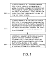
- FIG. 3 is a flowchart illustrating a method of transporting media in a printing apparatus according to an example.
- FIG. 4 is a flowchart illustrating a method of flushing media in a printing apparatus according to an example.
- FIG. 5 is a block diagram illustrating a computing device including a processor and a non-transitory, computer-readable storage medium to store instructions to flush media in a printing apparatus according to an example.
- a printing apparatus includes a toner applicator, a fuser, and a media transport assembly.
- the media transport assembly includes a simplex media path and a duplex media path.
- the simplex media path guides media to the toner applicator to position a respective side of the media towards the toner applicator to receive toner thereon and the fuser.
- the duplex media path guides the media to the simplex media path in a manner that another side of the media is positioned towards the toner applicator to receive toner thereon.
- Media may unintentionally stop in the media transport assembly due to firmware errors, losses of power, media jams, doors of printing apparatus being opened during the printing process, and the like.
- some of the media may be automatically advanced so that a user does not have to physically remove such media.
- automatic advancement may only be done if the media in front of other media is able to be advanced, for example, as determined by a control module including firmware having machine-readable instructions.
- a method of transporting media in a printing apparatus includes guiding the media in a forward simplex direction by a simplex media path of a media transport assembly of the printing apparatus. That is, a respective side of the media is positioned across from a toner applicator to receive toner thereon and a fuser to fuse the toner thereon by the simplex media path.
- the method also includes guiding the media in the forward duplex direction to the simplex media path by the duplex media path of the media transport assembly. That is, another aide of the media is positioned towards the toner applicator and the fuser to receive the toner thereon.
- the method also includes selectively moving the media in a reverse duplex direction opposite from the forward duplex direction to direct the media along the duplex media path to an output area outside of the media transport assembly by the control module in response to a media flushing event. That is, using the reverse duplex direction of the duplex media path in response to the media flushing event increases the amount of media that may be flushed from the media transport assembly without user intervention. Accordingly, a good user experience, a good perception of product reliability, and reduced opportunities for additional errors such as unintentionally leaving portions of the media in the media transport assembly may be attained.
- FIG. 1 is a block diagram illustrating a printing apparatus according to an example.
- a printing apparatus 100 includes a toner applicator 11 , a fuser 12 , a media transport assembly 13 , and a control module 14 .
- the toner applicator 11 applies toner to media.
- the toner applicator 11 may include an intermediate transport member such as an intermediate blanket to transport toner therefrom to the media.
- the toner applicator 11 may include an optical photoconductive drum, binary ink developers, toner cartridges, or the like, to transport toner therefrom to the media.
- the fuser 12 fuses the toner to the media.
- the fuser 12 may include a heated drum, and the like.
- the media transport assembly 13 includes a simplex media path 13 b and a duplex media path 13 a to transport the media.
- the simplex media path 12 b guides the media to the toner applicator 11 and the fuser 12 to position a respective side of the media towards the toner applicator 11 to receive the toner thereon.
- the duplex media path 13 a guides the media to the simplex media path 13 b in a manner that another side of the media is positioned towards the toner applicator 11 to receive the toner thereon.
- the control module 14 includes a movement member 14 a to selectively move the media along the duplex media path 13 a in a forward duplex direction to direct the media to the simplex media path 13 b .
- the movement member 14 a also selectively moves the media in a reverse duplex direction opposite from the forward duplex direction to direct the media to an output area outside of the media transport assembly 13 in response to a media flushing event.
- the movement member 14 a may include a first drive motor.
- control module 14 may be implemented in hardware, software including firmware, or combinations thereof.
- firmware may be stored in memory and executed by a suitable instruction-execution system.
- control module 14 may be implemented with any or a combination of technologies which are well known in the art (for example, discrete-logic circuits, application-specific integrated circuits (ASICs), programmable-gate arrays (PGAs), field-programmable gate arrays (FPGAs)), and/or other later developed technologies.
- ASICs application-specific integrated circuits
- PGAs programmable-gate arrays
- FPGAs field-programmable gate arrays
- the control module 14 may be implemented in a combination of software and data executed and stored under the control of a computing device.
- FIG. 2 is a schematic view of a printing apparatus according to an example.
- the printing apparatus 200 may include a toner applicator 11 , a fuser 12 , a media transport assembly 13 , and a control module 14 .
- the toner applicator 11 applies toner to media.
- the fuser 12 fuses the toner to the media.
- the media transport assembly 13 ( 13 a , 13 b , 23 c , 23 d , and 26 collectively 13 ) includes a simplex media path 13 b , a duplex media path 13 a , a media loading path 23 c , a media diverting path 23 d , and a media diverter 26 , to transport the media.
- the duplex media path 13 a may include a first set of feed rollers 25 a and the simplex media path may include a second set of feed rollers 13 b . That is, the simplex media path 13 b may include the second set of feed rollers 25 b to guide the media to the toner applicator 11 and the fuser 12 to position a respective side of the media towards the toner applicator 11 to receive the toner thereon.
- the media may be transported to an output tray 29 along the simplex media path 13 b after receiving toner and having the toner fused thereon.
- the media may first be transported from the simplex media path 13 b to the duplex media path 13 a and, subsequently, transported to the output tray 29 .
- the duplex media path 13 a may include the first set of feed rollers 25 a to guide the media to the simplex media path 13 b in a manner that another side of the media is positioned towards the toner applicator 11 to receive the toner thereon.
- the duplex media path 13 a may be disposed substantially parallel to the simplex media path 13 b and/or disposed to bypass the toner applicator 11 and the fuser 12 .
- the media loading path 23 c may include a third set of feed rollers 25 c to guide the media from at least one media input area to the simplex media path.
- the media diverting path 23 d may be disposed proximate to an intersection of the simplex media path 13 b and the duplex media path 13 a .
- the media diverter path 23 d communicates with the media diverter 26 to direct the media to the duplex media path 13 a based on the control module 14 in response to the media flushing event.
- the media diverter 26 selectively moves between a simplex position to direct the media to the simplex media path 13 b and a duplex position to direct the media to the duplex media path 13 a based on a control module 14 in response to the media flushing event.
- the media diverter 26 may include a movable gate, a movable path, and movable rollers.
- the control module 14 may include a first drive motor 24 a , a second drive motor 24 b , a third drive motor 24 c , and firmware 24 d .
- the first drive motor 24 a may include a forward driving direction and a reverse driving direction.
- the first drive motor 24 a moves the media along the duplex media path 13 a in the forward duplex direction d df when in the forward driving direction.
- the first drive motor 24 a moves the media along the duplex media path 13 a in the reverse duplex direction d dr when in the reverse driving direction in response to the media flushing event.
- the first drive motor 24 a selectively moves the media along the duplex media path 13 a in the forward duplex direction d df to direct the media to the simplex media path 13 b , and in the reverse duplex direction d dr opposite from the forward duplex direction d df to direct the media to an output area outside of the media transport assembly 13 in response to a media flushing event.
- the output area may include a duplex output tray 27 .
- the second drive motor 24 b may include a forward driving direction to move the media along the simplex media path 13 a in the forward simplex direction d sf .
- the second drive motor 24 b may be coupled to the second set of feed rollers 25 b to transport the media in the forward simplex direction d sf .
- the third drive motor 24 c may be coupled to the third set of feed rollers 25 c to guide the media from at least one media input area 28 to the simplex media path 13 b .
- the firmware 24 d may include machine-readable instructions to identify the media flushing event.
- the media flushing event may be an unintended stoppage of a media lacking unfused toner thereon.
- the unintended stoppage may be due to firmware errors, losses of power, media jams, doors of the printing apparatus 200 being opened during the printing process, and the like. Further, it is undesirable to flush media with unfused toner that may spread to other components in the media transport assembly 13 and likely cause print quality defects on subsequent media, and the like
- FIG. 3 is a flowchart illustrating a method of transporting media in a printing apparatus according to an example.
- the media in block S 310 , the media is guided in a forward simplex direction by a simplex media path of a media transport assembly of the printing apparatus to position a respective side of the media across from a toner applicator to receive toner thereon and a fuser to fuse the toner thereon.
- the media is guided in the forward duplex direction to the simplex media path by the duplex media path of the media transport assembly in a manner that another side of the media is positioned towards the toner applicator and the fuser to receive the toner thereon.
- the media is selectively moved in a reverse duplex direction opposite from the forward duplex direction to direct the media along the duplex media path to an output area outside of the media transport assembly by the control module in response to a media flushing event.
- the method may also include guiding the media by a media loading path of the media transport assembly from at least one media input area such as a media input tray to the simplex media path. Additionally, the method may also include directing the media to the duplex media path by a media diverter based on a control module in response to the media flushing event.
- FIG. 4 is a flowchart illustrating a method of flushing media in a printing apparatus according to an example.
- a first media is guided in a forward loading direction by a media loading path of a media transport assembly of the printing apparatus from at least one media input area to a simplex media path.
- the first media is guided in a forward simplex direction by the simplex media path of the media transport assembly to position a respective side of the first media across from a toner applicator to receive toner thereon and a fuser to fuse the toner thereon.
- the first media is guided in a forward duplex direction by the duplex media path of the media transport assembly in a manner that another side of the first media is positioned towards the toner applicator and the fuser to receive the toner thereon.
- a second media is directed by a media diverter along the media loading path to the duplex media path based on a control module in response to a media flushing event.
- the second media is selectively moved in a reverse duplex direction opposite from the forward duplex direction to direct the second media along the duplex media path to an output area outside of the media transport assembly based on a control module in response to the media flushing event.
- FIG. 5 is a block diagram illustrating a computing device including a processor and a non-transitory, computer-readable storage medium to store instructions to flush media in a printing apparatus according to an example.
- the non-transitory, computer-readable storage medium 55 may be included in a computing device 500 such as a printing apparatus to flush media therein.
- the non-transitory, computer-readable storage medium 55 may be implemented in whole or in part as instructions 57 such as computer-implemented instructions stored in the computing device locally or remotely, for example, in a server or a host computing device.
- the non-transitory, computer-readable storage medium 55 may correspond to a storage device that stores instructions 57 , such as computer-implemented instructions and/or programming code, and the like.
- the non-transitory, computer-readable storage medium 55 may include a non-volatile memory, a volatile memory, and/or a storage device.
- non-volatile memory include, but are not limited to, electrically erasable programmable read only memory (EEPROM) and read only memory (ROM).
- Examples of volatile memory include, but are not limited to, static random access memory (SRAM), and dynamic random access memory (DRAM).
- examples of storage devices include, but are not limited to, hard disk drives, compact disc drives, digital versatile disc drives, optical drives, and flash memory devices.
- the non-transitory, computer-readable storage medium 55 may even be paper or another suitable medium upon which the instructions 57 are printed, as the instructions 57 can be electronically captured, via, for instance, optical scanning of the paper or other medium, then compiled, interpreted or otherwise processed in a single manner, if necessary, and then stored therein.
- a processor 59 generally retrieves and executes the instructions 57 stored in the non-transitory, computer-readable storage medium 55 , for example, to operate a computing device 500 such a printing apparatus to flush media therein in accordance with an example.
- the non-transitory, computer-readable storage medium 55 can be accessed by the processor 59 .
- each block may represent a module, segment, or portion of code that includes one or more executable instructions to implement the specified logical function(s).
- each block may represent a circuit or a number of interconnected circuits to implement the specified logical function(s).
- FIGS. 3 and 4 illustrate a specific order of execution, the order of execution may differ from that which is depicted. For example, the order of execution of two or more blocks may be rearranged relative to the order illustrated. Also, two or more blocks illustrated in succession in FIGS. 3 and 4 may be executed concurrently or with partial concurrence. All such variations are within the scope of the present disclosure.
Landscapes
- Physics & Mathematics (AREA)
- General Physics & Mathematics (AREA)
- Control Or Security For Electrophotography (AREA)
Abstract
A method includes guiding the media n a forward simplex direction by a simplex media path of a media transport assembly of the printing apparatus to position a respective side of the media across from a toner applicator to receive toner thereon and a fuser to fuse the toner thereon. The method also includes guiding the media in a forward duplex direction to the simplex media path by the duplex media path of the media transport assembly so that another side of the media is positioned towards the toner applicator to receive the toner thereon. The method also includes selectively moving the media in a reverse duplex direction opposite from the forward duplex direction to direct the media along the duplex media path to an output area outside of the media transport assembly by the control module in response to a media flushing event.
Description
Printing apparatuses include toner applicators, fusers, and media transport assemblies. The media transport assembly includes a simplex media path and a duplex mega path. The simplex media path guides media to the toner applicator to position a respective side of the media towards the toner applicator to receive toner thereon and the fuser. The duplex media path guides the media to the simplex media path in a manner that another side of the media is positioned towards the toner applicator to receive toner thereon.
Non-limiting examples are described in the following description, read with reference to the figures attached hereto and do not limit the scope of the claims. Dimensions of components and features illustrated in the figures are chosen primarily for convenience and clarity of presentation and are not necessarily to scale. Referring to the attached figures:
A printing apparatus includes a toner applicator, a fuser, and a media transport assembly. The media transport assembly includes a simplex media path and a duplex media path. The simplex media path guides media to the toner applicator to position a respective side of the media towards the toner applicator to receive toner thereon and the fuser. The duplex media path guides the media to the simplex media path in a manner that another side of the media is positioned towards the toner applicator to receive toner thereon. Media, however, may unintentionally stop in the media transport assembly due to firmware errors, losses of power, media jams, doors of printing apparatus being opened during the printing process, and the like. When media is unintentionally stopped in the media transport assembly, some of the media may be automatically advanced so that a user does not have to physically remove such media. Generally, however, automatic advancement may only be done if the media in front of other media is able to be advanced, for example, as determined by a control module including firmware having machine-readable instructions.
As such, when a media jam occurs near an output of the printing apparatus, no media can be flushed out of the media transport assembly to prevent such flushing from causing damage to the printing apparatus. Accordingly, the amount of media that may be flushed out of the media transport assembly is low. Consequently, a user may have to manually locate the jammed media and remove it resulting in a poor user experience, a poor perception of product reliability, and increased opportunities for additional errors such as unintentionally leaving portions of the media in the media transport assembly.
In examples, a method of transporting media in a printing apparatus includes guiding the media in a forward simplex direction by a simplex media path of a media transport assembly of the printing apparatus. That is, a respective side of the media is positioned across from a toner applicator to receive toner thereon and a fuser to fuse the toner thereon by the simplex media path. The method also includes guiding the media in the forward duplex direction to the simplex media path by the duplex media path of the media transport assembly. That is, another aide of the media is positioned towards the toner applicator and the fuser to receive the toner thereon.
The method also includes selectively moving the media in a reverse duplex direction opposite from the forward duplex direction to direct the media along the duplex media path to an output area outside of the media transport assembly by the control module in response to a media flushing event. That is, using the reverse duplex direction of the duplex media path in response to the media flushing event increases the amount of media that may be flushed from the media transport assembly without user intervention. Accordingly, a good user experience, a good perception of product reliability, and reduced opportunities for additional errors such as unintentionally leaving portions of the media in the media transport assembly may be attained.
Referring to FIG. 1 , the simplex media path 12 b guides the media to the toner applicator 11 and the fuser 12 to position a respective side of the media towards the toner applicator 11 to receive the toner thereon. The duplex media path 13 a guides the media to the simplex media path 13 b in a manner that another side of the media is positioned towards the toner applicator 11 to receive the toner thereon. The control module 14 includes a movement member 14 a to selectively move the media along the duplex media path 13 a in a forward duplex direction to direct the media to the simplex media path 13 b. Alternatively, the movement member 14 a also selectively moves the media in a reverse duplex direction opposite from the forward duplex direction to direct the media to an output area outside of the media transport assembly 13 in response to a media flushing event. In some examples, the movement member 14 a may include a first drive motor.
In some examples, the control module 14 may be implemented in hardware, software including firmware, or combinations thereof. For example, the firmware may be stored in memory and executed by a suitable instruction-execution system. If implemented in hardware, as in an alternative example, the control module 14 may be implemented with any or a combination of technologies which are well known in the art (for example, discrete-logic circuits, application-specific integrated circuits (ASICs), programmable-gate arrays (PGAs), field-programmable gate arrays (FPGAs)), and/or other later developed technologies. In some examples, the control module 14 may be implemented in a combination of software and data executed and stored under the control of a computing device.
Referring to FIG. 2 , in some examples, the duplex media path 13 a may include a first set of feed rollers 25 a and the simplex media path may include a second set of feed rollers 13 b. That is, the simplex media path 13 b may include the second set of feed rollers 25 b to guide the media to the toner applicator 11 and the fuser 12 to position a respective side of the media towards the toner applicator 11 to receive the toner thereon. The media may be transported to an output tray 29 along the simplex media path 13 b after receiving toner and having the toner fused thereon. For duplex printing, the media may first be transported from the simplex media path 13 b to the duplex media path 13 a and, subsequently, transported to the output tray 29. Additionally, the duplex media path 13 a may include the first set of feed rollers 25 a to guide the media to the simplex media path 13 b in a manner that another side of the media is positioned towards the toner applicator 11 to receive the toner thereon. In some examples, the duplex media path 13 a may be disposed substantially parallel to the simplex media path 13 b and/or disposed to bypass the toner applicator 11 and the fuser 12.
Referring to FIG. 2 , in some examples, the media loading path 23 c may include a third set of feed rollers 25 c to guide the media from at least one media input area to the simplex media path. The media diverting path 23 d may be disposed proximate to an intersection of the simplex media path 13 b and the duplex media path 13 a. The media diverter path 23 d communicates with the media diverter 26 to direct the media to the duplex media path 13 a based on the control module 14 in response to the media flushing event. The media diverter 26 selectively moves between a simplex position to direct the media to the simplex media path 13 b and a duplex position to direct the media to the duplex media path 13 a based on a control module 14 in response to the media flushing event. In some examples, the media diverter 26 may include a movable gate, a movable path, and movable rollers.
Referring to FIG. 2 , in some examples, the control module 14 may include a first drive motor 24 a, a second drive motor 24 b, a third drive motor 24 c, and firmware 24 d. The first drive motor 24 a may include a forward driving direction and a reverse driving direction. For example, the first drive motor 24 a moves the media along the duplex media path 13 a in the forward duplex direction ddf when in the forward driving direction. Alternatively, the first drive motor 24 a moves the media along the duplex media path 13 a in the reverse duplex direction ddr when in the reverse driving direction in response to the media flushing event. That is, the first drive motor 24 a selectively moves the media along the duplex media path 13 a in the forward duplex direction ddf to direct the media to the simplex media path 13 b, and in the reverse duplex direction ddr opposite from the forward duplex direction ddf to direct the media to an output area outside of the media transport assembly 13 in response to a media flushing event. In some examples, the output area may include a duplex output tray 27.
Referring to FIG. 2 , in some examples, the second drive motor 24 b may include a forward driving direction to move the media along the simplex media path 13 a in the forward simplex direction dsf. For example, the second drive motor 24 b may be coupled to the second set of feed rollers 25 b to transport the media in the forward simplex direction dsf. The third drive motor 24 c may be coupled to the third set of feed rollers 25 c to guide the media from at least one media input area 28 to the simplex media path 13 b. The firmware 24 d may include machine-readable instructions to identify the media flushing event. For example, the media flushing event may be an unintended stoppage of a media lacking unfused toner thereon. The unintended stoppage may be due to firmware errors, losses of power, media jams, doors of the printing apparatus 200 being opened during the printing process, and the like. Further, it is undesirable to flush media with unfused toner that may spread to other components in the media transport assembly 13 and likely cause print quality defects on subsequent media, and the like
Referring to FIG. 5 , in some examples, the non-transitory, computer-readable storage medium 55 may correspond to a storage device that stores instructions 57, such as computer-implemented instructions and/or programming code, and the like. For example, the non-transitory, computer-readable storage medium 55 may include a non-volatile memory, a volatile memory, and/or a storage device. Examples of non-volatile memory include, but are not limited to, electrically erasable programmable read only memory (EEPROM) and read only memory (ROM). Examples of volatile memory include, but are not limited to, static random access memory (SRAM), and dynamic random access memory (DRAM).
Referring to FIG. 5 , examples of storage devices include, but are not limited to, hard disk drives, compact disc drives, digital versatile disc drives, optical drives, and flash memory devices. In some examples, the non-transitory, computer-readable storage medium 55 may even be paper or another suitable medium upon which the instructions 57 are printed, as the instructions 57 can be electronically captured, via, for instance, optical scanning of the paper or other medium, then compiled, interpreted or otherwise processed in a single manner, if necessary, and then stored therein. A processor 59 generally retrieves and executes the instructions 57 stored in the non-transitory, computer-readable storage medium 55, for example, to operate a computing device 500 such a printing apparatus to flush media therein in accordance with an example. In an example, the non-transitory, computer-readable storage medium 55 can be accessed by the processor 59.
It is to be understood that the flowcharts of FIGS. 3 and 4 illustrate architecture, functionality, and/or operation of examples of the present disclosure. If embodied in software, each block may represent a module, segment, or portion of code that includes one or more executable instructions to implement the specified logical function(s). If embodied in hardware, each block may represent a circuit or a number of interconnected circuits to implement the specified logical function(s). Although the flowcharts of FIGS. 3 and 4 illustrate a specific order of execution, the order of execution may differ from that which is depicted. For example, the order of execution of two or more blocks may be rearranged relative to the order illustrated. Also, two or more blocks illustrated in succession in FIGS. 3 and 4 may be executed concurrently or with partial concurrence. All such variations are within the scope of the present disclosure.
The present disclosure has been described using non-limiting detailed descriptions of examples thereof that are not intended to limit the scope of the general inventive concept. It should be understood that features and/or operations described with respect to one example may be used with other examples and that not all examples have all of the features and/or operations illustrated in a particular figure or described with respect to one of the examples. Variations of examples described will occur to persons of the art. Furthermore, the terms “comprise,” “include,” “have” and their conjugates, shall mean, when used in the disclosure and/or claims, “including but not necessarily limited to.”
It is noted that some of the above described examples may include structure, acts or details of structures and acts that may not be essential to the general inventive concept and which are described for illustrative purposes. Structure and acts described herein are replaceable by equivalents, which perform the same function, even if the structure or acts are different, as known in the art. Therefore, the scope of the general inventive concept is limited only by the elements and limitations as used in the claims.
Claims (15)
1. A printing apparatus, comprising:
a toner applicator to apply toner to media;
a fuser to fuse the toner to the media; and
a media transport assembly to transport the media, the media transport assembly including a simplex media path and a duplex media path;
the simplex media path to guide the media to the toner applicator to position a respective side of the media towards the toner applicator to receive the toner thereon and the fuser; and
the duplex media path to guide the media to the simplex media path in a manner that another side of the media is positioned towards the toner applicator to receive the toner thereon; and
a control module including a movement member to selectively move the media along the duplex media path in a forward duplex direction to direct the media to the simplex media path, and a reverse duplex direction opposite from the forward duplex direction to direct the media to bypass the simplex media path to an output area outside of the media transport assembly in response to a media flushing event,
wherein, in response to the media flushing event, the control module is to move media path in the reverse duplex direction from both the simplex media path and a media input area.
2. The printing apparatus of claim 1 , wherein the movement member comprises:
a first drive motor having a forward driving direction and a reverse driving direction;
the first drive motor to move the media along the duplex media path in the forward duplex direction when in the forward driving direction; and
the first drive motor to move the media along the duplex media path in the reverse duplex direction when in the reverse driving direction in response to the media flushing event.
3. The printing apparatus of claim 2 , wherein the duplex media path comprises:
a first set of feed rollers coupled to the first drive motor to transport the media in the forward duplex direction and the reverse duplex direction.
4. The printing apparatus of claim 1 , wherein the control module further comprises:
a second drive motor having a forward driving direction to move the media along the simplex media path in a forward simplex direction.
5. The printing apparatus of claim 4 , wherein the simplex media path comprises a second set of feed rollers coupled to the second drive motor to transport the media in the forward simplex direction and the media transport assembly further includes a media loading path including a third set of feed rollers coupled to a third drive motor to guide the media from at least one media input area to the simplex media path.
6. The printing apparatus of claim 1 wherein the media flushing event is an unintended stoppage of a media lacking unfused toner thereon.
7. The printing apparatus of claim 1 , wherein the media transport assembly further comprises:
a media diverter to selectively move between a simplex position to direct the media to the simplex media path and a duplex position to direct the media to the duplex media path based on the control module in response to the media flushing event.
8. The printing apparatus of claim 7 , wherein the media transport assembly further comprises:
a media diverting path disposed proximate to an intersection of the simplex media path and the duplex media path, the media diverter path to communicate with the media diverter to direct the media to the duplex media path based on the control module in response to the media flushing event.
9. The printing apparatus of claim 1 , wherein the duplex media path is disposed substantially parallel to the simplex media path.
10. The printing apparatus of claim 1 , wherein the duplex media path is disposed to bypass the toner applicator and the fuser.
11. The printing apparatus of claim 1 , wherein the output area comprises:
a duplex output tray.
12. The printing apparatus of claim 1 , wherein the control module further comprises:
firmware including machine-readable instructions to identify the media flushing event.
13. A method of transporting media in a printing apparatus, the method comprising:
guiding the media from a media input area in a forward simplex direction by a simplex media path of a media transport assembly of the printing apparatus to position a respective side of the media across from a toner applicator to receive toner thereon and a fuser to fuse the toner thereon;
guiding the media in a forward duplex direction to the simplex media path by a duplex media path of the media transport assembly in a manner that another side of the media is positioned towards the toner applicator and the fuser to receive the toner thereon; and
in response to a media flushing event, selectively moving the media and additional media from the media input area in a reverse duplex direction opposite from the forward duplex direction to direct the media along the duplex media path, bypassing the simplex media path, to an output area outside of the media transport assembly by a control module in response to a media flushing event.
14. The method of claim 13 , further comprising:
guiding the media by a media loading path of the media transport assembly from at least one media input area to the simplex media path; and
directing the media to the duplex media path by a media diverter based on the control module in response to the media flushing event.
15. A non-transitory computer-readable storage medium having computer executable instructions stored thereon to flush media in a printing apparatus, the instructions are executable by a processor to:
guide a first media in a forward loading direction by a media loading path of a media transport assembly of the printing apparatus from at least one media input area to a simplex media path;
guide the first media in a forward simplex direction by the simplex media path of the media transport assembly to position a respective side of the first media across from a toner applicator to receive toner thereon and a fuser to fuse the toner thereon;
guide the first media in a forward duplex direction by a duplex media path of the media transport assembly in a manner that another side of the first media is positioned towards the toner applicator and the fuser to receive the toner thereon; and
in response to a media flushing event:
selectively move the first media in a reverse duplex direction opposite from the forward duplex direction to direct the first media along the duplex media path to an output area outside of the media transport assembly;
direct a second media by a media diverter along the media loading path to the duplex media path based on a control module; and
selectively move the second media in the reverse duplex direction opposite from the forward duplex direction to direct the second media along the duplex media path, bypassing the simplex media path, to the output area.
Applications Claiming Priority (1)
| Application Number | Priority Date | Filing Date | Title |
|---|---|---|---|
| PCT/US2014/055007 WO2016039743A1 (en) | 2014-09-10 | 2014-09-10 | Moving media in reverse duplex direction along media duplex path |
Publications (2)
| Publication Number | Publication Date |
|---|---|
| US20170190542A1 US20170190542A1 (en) | 2017-07-06 |
| US10087043B2 true US10087043B2 (en) | 2018-10-02 |
Family
ID=55459367
Family Applications (1)
| Application Number | Title | Priority Date | Filing Date |
|---|---|---|---|
| US15/510,637 Active US10087043B2 (en) | 2014-09-10 | 2014-09-10 | Moving media in reverse duplex direction along media duplex path |
Country Status (2)
| Country | Link |
|---|---|
| US (1) | US10087043B2 (en) |
| WO (1) | WO2016039743A1 (en) |
Citations (15)
| Publication number | Priority date | Publication date | Assignee | Title |
|---|---|---|---|---|
| JPH02277670A (en) | 1989-04-19 | 1990-11-14 | Pfu Ltd | Controlling method for printer |
| JPH0753463A (en) | 1984-12-12 | 1995-02-28 | Syntex Usa Inc | Alkoxymethyl ether and alkoxymethyl ester derivatives |
| EP0872778A1 (en) | 1997-04-14 | 1998-10-21 | Xerox Corporation | Internal purge for easy jam clearance in copiers/printers |
| US5974290A (en) | 1998-02-24 | 1999-10-26 | Ricoh Company, Ltd. | Image forming apparatus having sheet guide members openable for removing a jammed sheet |
| US5984305A (en) | 1997-05-15 | 1999-11-16 | Ricoh Company, Ltd. | Image forming apparatus having releasable sheet conveying paths and method of use |
| JP2003241458A (en) | 2002-02-22 | 2003-08-27 | Canon Inc | Image forming apparatus |
| US6621997B2 (en) | 2001-12-06 | 2003-09-16 | Samsung Electronic Co., Ltd. | Multi-function actuator of duplex printer |
| US6694116B2 (en) | 2001-01-22 | 2004-02-17 | Sharp Kabushiki Kaisha | Sheet-like object conveying apparatus |
| US6757501B2 (en) | 2002-03-08 | 2004-06-29 | Panasonic Communications Co., Ltd. | Multifunctional printer and copier |
| US7871075B2 (en) | 2005-08-12 | 2011-01-18 | Ricoh Co., Ltd. | Image forming apparatus and sheet conveyance apparatus for improving jam-handling capability using a lever attached to a roller pair |
| JP2011123104A (en) | 2009-12-08 | 2011-06-23 | Konica Minolta Business Technologies Inc | Image forming system |
| US20110211007A1 (en) | 2010-02-26 | 2011-09-01 | Canon Kabushiki Kaisha | Printing apparatus and jam restoration method in printing apparatus |
| JP2011178494A (en) | 2010-02-26 | 2011-09-15 | Canon Inc | Image forming apparatus |
| JP2013001531A (en) | 2011-06-20 | 2013-01-07 | Kyocera Document Solutions Inc | Sheet material feeding device and image forming apparatus including the same |
| US8391730B2 (en) * | 2008-11-12 | 2013-03-05 | Canon Kabushiki Kaisha | Image forming apparatus |
-
2014
- 2014-09-10 US US15/510,637 patent/US10087043B2/en active Active
- 2014-09-10 WO PCT/US2014/055007 patent/WO2016039743A1/en not_active Ceased
Patent Citations (16)
| Publication number | Priority date | Publication date | Assignee | Title |
|---|---|---|---|---|
| JPH0753463A (en) | 1984-12-12 | 1995-02-28 | Syntex Usa Inc | Alkoxymethyl ether and alkoxymethyl ester derivatives |
| JPH02277670A (en) | 1989-04-19 | 1990-11-14 | Pfu Ltd | Controlling method for printer |
| EP0872778A1 (en) | 1997-04-14 | 1998-10-21 | Xerox Corporation | Internal purge for easy jam clearance in copiers/printers |
| US5984305A (en) | 1997-05-15 | 1999-11-16 | Ricoh Company, Ltd. | Image forming apparatus having releasable sheet conveying paths and method of use |
| US5974290A (en) | 1998-02-24 | 1999-10-26 | Ricoh Company, Ltd. | Image forming apparatus having sheet guide members openable for removing a jammed sheet |
| US6694116B2 (en) | 2001-01-22 | 2004-02-17 | Sharp Kabushiki Kaisha | Sheet-like object conveying apparatus |
| US6621997B2 (en) | 2001-12-06 | 2003-09-16 | Samsung Electronic Co., Ltd. | Multi-function actuator of duplex printer |
| JP2003241458A (en) | 2002-02-22 | 2003-08-27 | Canon Inc | Image forming apparatus |
| US6757501B2 (en) | 2002-03-08 | 2004-06-29 | Panasonic Communications Co., Ltd. | Multifunctional printer and copier |
| US7871075B2 (en) | 2005-08-12 | 2011-01-18 | Ricoh Co., Ltd. | Image forming apparatus and sheet conveyance apparatus for improving jam-handling capability using a lever attached to a roller pair |
| US8391730B2 (en) * | 2008-11-12 | 2013-03-05 | Canon Kabushiki Kaisha | Image forming apparatus |
| JP2011123104A (en) | 2009-12-08 | 2011-06-23 | Konica Minolta Business Technologies Inc | Image forming system |
| US20110211007A1 (en) | 2010-02-26 | 2011-09-01 | Canon Kabushiki Kaisha | Printing apparatus and jam restoration method in printing apparatus |
| JP2011178494A (en) | 2010-02-26 | 2011-09-15 | Canon Inc | Image forming apparatus |
| US8047539B2 (en) | 2010-02-26 | 2011-11-01 | Canon Kabushiki Kaisha | Image forming apparatus |
| JP2013001531A (en) | 2011-06-20 | 2013-01-07 | Kyocera Document Solutions Inc | Sheet material feeding device and image forming apparatus including the same |
Non-Patent Citations (1)
| Title |
|---|
| International Searching Authority. ISA/KR. International Search Report. Date of mailing May 8, 2015. Application No. PCT/US2014/055007. Filing date Sep. 10, 2014. |
Also Published As
| Publication number | Publication date |
|---|---|
| US20170190542A1 (en) | 2017-07-06 |
| WO2016039743A1 (en) | 2016-03-17 |
Similar Documents
| Publication | Publication Date | Title |
|---|---|---|
| US20180239289A1 (en) | Image forming apparatus and controlling method thereof | |
| JP6060656B2 (en) | ROLLED RECORDED MEDIUM CONVEYING DEVICE, IMAGE FORMING DEVICE, ROLLED RECORDED MEDIUM CONVEYING METHOD, AND ROLLED RECORDED MEDIUM CONVEYING PROGRAM | |
| JPS6079998A (en) | Page turn-over device for booklets | |
| US9137403B2 (en) | Image forming apparatus | |
| US8670011B2 (en) | Erasing apparatus and image erasing method | |
| JP5860016B2 (en) | Image forming apparatus | |
| US10294068B2 (en) | Image forming apparatus | |
| JP6639352B2 (en) | Recording apparatus, control method thereof, and program | |
| US8698861B2 (en) | Color erasing apparatus and color erasing heat source unit | |
| JP6398842B2 (en) | Image forming apparatus | |
| US10087043B2 (en) | Moving media in reverse duplex direction along media duplex path | |
| US11554927B2 (en) | Sheet conveyance apparatus and image forming apparatus | |
| US11429048B2 (en) | Image forming apparatus that can form images on both sides of sheet by inverting sheet | |
| JP6613985B2 (en) | Printing apparatus and printing method | |
| US20170305712A1 (en) | Image forming apparatus | |
| US9079438B1 (en) | Printer | |
| JP2007008689A (en) | Image forming device | |
| JP2015020884A (en) | Image forming apparatus | |
| JP2010072065A (en) | Image forming apparatus | |
| US8371579B2 (en) | Sheet alignment apparatus and image forming system using the same | |
| US20150241832A1 (en) | Medium transportation apparatus and image forming apparatus | |
| JP2016180847A (en) | Image forming apparatus | |
| US20250106333A1 (en) | Recording medium processing apparatus and image forming system | |
| US9386177B2 (en) | Information processing apparatus and original reading apparatus | |
| US8985729B1 (en) | Methods and apparatus for automatic recovery within an imaging device |
Legal Events
| Date | Code | Title | Description |
|---|---|---|---|
| AS | Assignment |
Owner name: HEWLETT-PACKARD DEVELOPMENT COMPANY, L.P., TEXAS Free format text: ASSIGNMENT OF ASSIGNORS INTEREST;ASSIGNOR:ELLIS, DANIEL S.;REEL/FRAME:043160/0720 Effective date: 20140909 |
|
| STCF | Information on status: patent grant |
Free format text: PATENTED CASE |
|
| CC | Certificate of correction | ||
| MAFP | Maintenance fee payment |
Free format text: PAYMENT OF MAINTENANCE FEE, 4TH YEAR, LARGE ENTITY (ORIGINAL EVENT CODE: M1551); ENTITY STATUS OF PATENT OWNER: LARGE ENTITY Year of fee payment: 4 |