US10086915B2 - Collapsible privacy enclosure - Google Patents
Collapsible privacy enclosure Download PDFInfo
- Publication number
- US10086915B2 US10086915B2 US15/339,457 US201615339457A US10086915B2 US 10086915 B2 US10086915 B2 US 10086915B2 US 201615339457 A US201615339457 A US 201615339457A US 10086915 B2 US10086915 B2 US 10086915B2
- Authority
- US
- United States
- Prior art keywords
- middle frame
- frame
- shaped
- collapsible enclosure
- pivotally connected
- Prior art date
- Legal status (The legal status is an assumption and is not a legal conclusion. Google has not performed a legal analysis and makes no representation as to the accuracy of the status listed.)
- Active, expires
Links
Images


Classifications
-
- B—PERFORMING OPERATIONS; TRANSPORTING
- B63—SHIPS OR OTHER WATERBORNE VESSELS; RELATED EQUIPMENT
- B63B—SHIPS OR OTHER WATERBORNE VESSELS; EQUIPMENT FOR SHIPPING
- B63B29/00—Accommodation for crew or passengers not otherwise provided for
- B63B29/02—Cabins or other living spaces; Construction or arrangement thereof
- B63B29/04—Furniture peculiar to vessels
- B63B2029/043—Seats; Arrangements thereof on vessels
Definitions
- a marine privacy enclosure is a space that may be provided on a boat or elsewhere for enclosing a head or an area for changing clothes.
- Some marine privacy enclosures comprise fabric curtains that may be attached to and hung from a Bimini top or a hard top. Such curtains may be removed and stowed when not in use.
- Other marine privacy enclosures comprise convertible structures that may function as a privacy enclosure when deployed and as seating when stowed. Such convertible structures may provide a frame from which to hang a removable fabric curtain.
- FIG. 1 is a perspective view of a framework of an illustrative collapsible enclosure according to the present disclosure, with the framework in a fully deployed position;
- FIG. 2 is a perspective view of a framework of an illustrative collapsible enclosure according to the present disclosure, with the framework in a partially deployed position;
- FIG. 3 is an end elevation view of the framework of the illustrative collapsible enclosure of FIG. 1 , with the frame work in a fully deployed position;
- FIG. 4 is a rear elevation view of the framework of the illustrative collapsible enclosure of FIG. 1 , with the frame work in a fully deployed position;
- FIG. 5 is a perspective view of the framework of the illustrative collapsible enclosure of FIG. 1 , with the frame work in a collapsed position;
- FIG. 6 is an end elevation view of the framework of the illustrative collapsible enclosure of FIG. 1 , with the frame work in a collapsed position;
- FIG. 7 is a rear elevation view of the framework of the illustrative collapsible enclosure of FIG. 1 , with the frame work in a collapsed position;
- FIG. 8 is a top plan view of the framework of the illustrative collapsible enclosure of FIG. 1 , with the frame work in a collapsed position;
- FIG. 9 is a perspective view of a lower frame section of the illustrative collapsible enclosure of FIG. 1 ;
- FIG. 10 is a perspective view of a first side portion of a middle frame section of the illustrative collapsible enclosure of FIG. 1 in a fully deployed position;
- FIG. 11 is a perspective view of the first side portion of the middle frame section of FIG. 8 in a collapsed position
- FIG. 12 is a perspective view of an upper frame section of the illustrative collapsible enclosure of FIG. 11 in a partially deployed position;
- FIG. 13 is a perspective view of the upper frame section of FIG. 12 in a collapsed position
- FIG. 14 is a perspective view of a framework of another illustrative collapsible enclosure according to the present disclosure, with the framework in a fully deployed position;
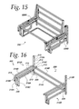
- FIG. 15 is a perspective view of the framework of the illustrative collapsible enclosure of FIG. 14 , with the frame work in a collapsed position;
- FIG. 16 is a perspective view of a lower frame section of the illustrative collapsible enclosure of FIG. 14 ;
- FIG. 17 is a perspective view of a first side portion of a middle frame section of the illustrative collapsible enclosure of FIG. 14 in a fully deployed position;
- FIG. 18 is a perspective view of the first side portion of the middle frame section of FIG. 17 in a collapsed position
- FIG. 19 is perspective view of an upper frame section of the illustrative collapsible enclosure of FIG. 11 in a fully deployed position;
- FIG. 20 is a perspective view of an upper frame section of the illustrative collapsible enclosure of FIG. 11 in a collapsed position;
- FIG. 21 is a perspective view of a further embodiment of a lower frame section of a collapsible enclosure according to the present disclosure.
- FIGS. 1-13 show an illustrative embodiment of a collapsible enclosure 100 according to the present disclosure.
- the collapsible enclosure 100 includes a frame that can be transitioned between a first (or deployed or enclosure) configuration, as best shown in FIG. 1 , and a second (or collapsed or seating) configuration, as best shown in FIG. 5 .
- the frame is provided in three sections, namely, a lower frame section 102 , a middle frame section 104 , and an upper frame section 106 .
- the lower frame section 102 includes a back portion 108 and first and second side portions 110 A, 110 B.
- the back portion 108 is shown as including first and second spaced-apart, parallel vertical posts 112 A, 112 B and first and second spaced-apart, parallel horizontal beams 114 A, 114 B, each having a first end attached to the first post 112 A and a second end attached to the second post 112 B.
- the first beam 114 A is attached to the first and second posts 112 A, 112 B near respective lower ends thereof, and the second beam 114 B is attached to the first and second posts near respective midpoints thereof.
- Each of the first vertical post 112 A and the second horizontal beam 116 B may define one or more apertures 113 extending therein or there through for receiving fasteners (not shown) that may be used to attach other components thereto, as will be discussed further below.
- the first and second side portions 110 A, 110 B are shown as mirror images of each other. As such, only the first side portion 110 A will be described herein in detail.
- the first side portion 110 A includes first and second spaced apart and parallel horizontal beams 116 A, 116 B extending between the first vertical post 112 A of the back portion to a first vertical post 118 A of the first side portion.
- the first side portion 110 A also includes third and fourth spaced apart and parallel horizontal beams 116 C, 116 D extending, respectively, from the first and second horizontal beams 114 A, 114 B of the back portion 108 to a second vertical post 118 B of the first side portion.
- a first strap 120 A connects a lower portion of the first post 118 A of the first side portion 110 A to a lower portion of the second post 118 B of the first side portion.
- a second strap 120 B connects an intermediate portion of the first post 118 A of the first side portion 110 A to an upper portion of the second post 118 B of the first side portion.
- the first and second horizontal beams 116 A, 116 B of the first side portion 110 A define a first vertical plane
- the third and fourth horizontal beams of the first side portion define a second vertical plane parallel to and spaced apart from the first vertical plane.
- the middle frame section 104 includes a first side portion 104 A and a second side portion 104 B.
- the first side portion 104 A is connected to the second side portion 104 B by first and second horizontal beams 105 A, 105 B.
- the first and second side portions 104 A, 104 B are shown as identical to or mirror images of each other. As such, only the first side portion 104 A will be described herein in detail.
- the first side portion 104 A includes first, second, third, and fourth L-shaped sections 122 A, 122 B, 122 C, 122 D pivotally connected to each other. More specifically, the first side portion 104 A includes a first L-shaped section 122 A, a second L-shaped section 122 B pivotally connected to the first L-shaped section by a first hinge 124 A, a third L-shaped section 122 C pivotally connected to the second L-shaped section by a second hinge 124 B, and a fourth L-shaped section 122 D pivotally connected to the third L-shaped section by a third hinge 124 C. The fourth L-shaped section 122 D also is pivotally connected to the first L-shaped section 122 A by a fourth hinge 124 D.
- Each of the L-shaped sections 122 A, 122 B, 122 C, 122 D is defined by a first leg and a second leg generally perpendicular to the first leg.
- the first and second legs of each L-shaped section are identified in the drawings with (and may be referred to herein using) the suffixes “ 1 ” and “ 2 ”, respectively.
- the first and second legs of individual ones of the L-shaped sections 122 A, 122 B, 122 C, 122 D are generally of equal length.
- the first and second legs of the first L-shaped section 122 A are generally the same length of the first and second legs of the third L-shaped section 122 C.
- first and second legs of the second L-shaped section 122 B are generally the same length of the first and second legs of the fourth L-shaped section 122 D.
- the first and second legs of the first and third L-shaped sections 122 A, 122 C are relatively short compared to the first and second legs of the second and fourth L-shaped sections 122 B, 122 D.
- the first and second legs of the first and third L-shaped sections 122 A, 122 C are about half as long as the first and second legs of the second and fourth L-shaped sections 122 B, 122 D.
- the L-shaped sections 122 A, 122 B, 122 C, 122 D are shown as having rectangular cross-sections. In other embodiments, the L-shaped sections 122 A, 122 B, 122 C, 122 D could have other cross-sections. They could be solid or tubular.
- the first and second legs thereof could be formed monolithically by bending a piece of stock to the desired form, by joining individual pieces of stock by welding, bonding, or using mechanical fasteners, or any combination thereof.
- Each of the L-shaped sections 122 A, 122 B, 122 C, 122 D may include a stiffener 122 A 3 , 122 B 3 , 122 C 3 , 122 D 3 joining the first and second legs thereof.
- each of the L-shaped sections 122 A, 122 B, 122 C, 122 D may include a stiffener 122 A 3 , 122 B 3 , 122 C 3 , 122 D 3 joining the first and second legs thereof such that the respective first leg, second leg, and stiffener form an isosceles triangle.
- the stiffeners 122 A 3 , 122 B 3 , 122 C 3 , 122 D 3 could be attached to the first and second legs by welding, bonding, using mechanical fasteners, or any combination thereof.
- the first side portion 104 A of the middle frame section 104 is reconfigurable between a first (or deployed) configuration and a second (or collapsed) configuration (the second side portion 104 B of the middle frame section 104 is similarly reconfigurable).
- adjacent legs of the first, second, third, and fourth L-shaped sections 122 A, 122 B, 122 C, 122 D are generally collinear, and the first side portion of the middle frame section 104 , viewed from the side, has a generally rectangular form.
- adjacent legs of the first, second, third, and fourth L-shaped sections 122 A, 122 B, 122 C, 122 D are generally perpendicular to each other, and the first side portion 104 A of the middle frame section 104 , viewed from the side, has a generally Z-shaped form.
- the stiffeners 122 A 3 , 122 D 3 of the first and fourth sections L-shaped sections 122 A, 122 D are generally collinear, and the stiffeners 122 B 3 , 122 C 3 of the second and third L-shaped sections 122 B, 122 C are generally collinear.
- third L-shaped section 122 C of the first side portion 104 A of the middle frame section 104 is fixed to the lower frame section 102 .
- third L-shaped section 122 C may be fixed to one or both of the first vertical post 112 A and the second horizontal beam 116 B of the lower frame section using fasteners (not shown) or otherwise.
- the third L-shaped section 122 C remains stationary with respect to the lower frame section 102 and the first, second, and fourth L-shaped sections 122 A, 122 B, 122 D, the second and fourth L-shaped sections rotate in a first direction with respect to the third L-shaped section and the first L-shaped section, and the first L-shaped section translates with respect to the third L-shaped section. More specifically, as viewed from the perspective of FIGS.
- the second and fourth L-shaped sections 122 B, 122 D rotate counterclockwise with respect to the third L-shaped section 122 C and the first L-shaped section 122 A translates to the left and downward with respect to the third L-shaped section.
- the reverse movements occur.
- the first through fourth L-shaped sections 122 A- 122 D and the first though fourth hinges 124 A- 124 D are configured so that, as the first side portion 104 A is transitioned between the first and second configurations, the first leg 122 A 1 of the first L-shaped section remains parallel to the first leg 122 C 1 of the third L-shaped section, and the second leg 122 A 2 of the first L-shaped section remains parallel to the second leg 122 C 2 of the third L-shaped section.
- first and second horizontal side rails 116 A, 116 B of the lower frame section 102 and the third and fourth horizontal side rails 116 C, 116 D of the lower frame section 102 cooperate to define a space receiving at least a portion of at least some of the first through fourth L-shaped sections 122 A- 122 D of the first side portion 104 A, especially when the first side portion is in the collapsed configuration.
- a first support strut 126 A may be pivotally connected between the lower frame section 102 and the fourth L-shaped section 122 D of the first side portion 104 A of the middle frame section 104 to assist a user in transitioning the middle frame section 104 between the first and second positions.
- a first end of the first support strut 126 A is pivotally connected to a lower portion of the first vertical post 112 A via an intervening bracket 129
- second end of the first support strut 126 A is pivotally connected to the fourth L-shaped section 122 D via an intervening bracket 125 attached to the first leg 122 D 1 of the fourth L-shaped section.
- the first support strut 126 A may be a telescopic actuator, for example, a gas strut.
- a second support strut 126 B analogous to the first support strut 126 A is shown as pivotally connected between the lower frame section 102 and the second side portion 104 B of the middle frame section 104 in an analogous manner.
- the second side portion 104 B of the middle frame section 104 may be configured in a manner substantially similar to the first side portion 104 A of the middle frame section 104 . Also, the second side portion 104 B may be connected to the lower frame section 102 in a similar manner similar to the first side portion 104 A and transition between first and second positions in a manner substantially similar to the first side portion 104 A.
- the upper frame section 106 includes a base portion 128 and a tilting portion 130 pivotally connected to the base portion.
- the base portion 128 includes first and second parallel and spaced-apart horizontal side beams 128 A, 128 B and a horizontal rear beam 128 C connected between respective first (or rear) ends of the first and second side beams.
- the first and second side beams 128 A, 128 B of the base portion 128 are connected, respectively, to opposing surfaces of the first L-shaped sections 122 A of the first and second side portions 104 A, 104 B of the middle frame section 104 .
- the tilting portion 130 includes a bottom portion 132 , first and second opposed, parallel and spaced-apart side portions 134 A, 134 B, and a rear beam 136 connecting rear portions of the first and second side portions.
- the bottom portion 132 includes a seat frame 140 having a front beam 140 A, a rear beam 140 B, and first and second side beams 140 C, 140 D connecting respective first and second ends of the front and rear beams.
- the front and rear beams 140 A, 140 B are shown as square tubular members, and the first and second side beams 140 C, 140 D are shown as structural angles.
- the first and second side beams 140 C, 140 D of the seat frame are pivotally connected at respective first (or rear) ends thereof to the respective side beams 128 A, 128 B of the base portion 128 proximate the rear beam 128 C thereof.
- the first and second side beams 140 C, 140 D of the seat frame may be notched or otherwise configured as might be necessary to permit pivoting thereof with respect to the respective side beams 128 A, 128 B of the base portion 128
- the bottom portion 132 also includes a seat web 142 .
- the seat web 142 is shown as a grid of metal or fabric attached to the front, rear, and first and second side beams 140 A, 140 B, 140 C, 140 D of the seat frame.
- the seat web 142 may be configured and/or attached to the seat frame in other ways.
- a U-shaped curtain rod 146 is pivotally attached to the bottom portion 132 via first and second brackets 148 A, 148 B located at an underside of the front beam 140 A of the seat frame 140 .
- the upper frame section 106 also includes first and second support struts 144 A, 144 B pivotally connected between the base portion 128 and the tilting portion 130 .
- the first and second support struts 144 A, 144 B are telescopic actuators, for example, gas struts, pivotally at respective first ends thereof to respective intermediate portions of the first and second side beams 128 A, 128 B of the base portion 128 , and pivotally connected at respective second ends thereof to respective intermediate portions of the first and second side beams 140 C, 140 D of the seat frame 140 .
- the first and second support struts 144 A, 144 B could be pivotally connected to spaced-apart portions of the front beam 140 A of the seat frame.
- the first and second side portions 134 A, 134 B of the upper frame section 106 are shown as identical to or mirror images of each other. As such, only the first side portion 134 A will be described in detail herein.
- the first side portion 134 A includes a lower, L-shaped section 150 and an upper, J-shaped section 152 .
- the lower L-shaped section 150 is oriented with the free end of a first leg 150 A thereof generally perpendicular to and attached to the first side beam 140 C of the seat frame proximate the second end thereof.
- the upper J-shaped section 152 is oriented with the free end of a first leg 152 A thereof generally perpendicular to and attached to the first side beam 140 A of the seat frame proximate the first end thereof.
- the lower L-shaped section 150 is further oriented with the free end of a second leg 150 B thereof generally parallel to and spaced from the first side beam 140 C of the seat frame, and generally perpendicular and attached to the first leg 152 A of the upper J-shaped section 152 A intermediate the free end and a second end thereof.
- the upper J-shaped section 152 is further oriented with the free end of a third leg 152 C thereof generally perpendicular to and attached to the second leg 150 B of the lower L-shaped section 150 intermediate the free end and a second end thereof.
- the upper J-shaped section 152 also includes a second leg 152 B extending between second ends of the first leg 152 A and the third leg 152 C thereof.
- the first side portion 134 A may include one or more brackets or tabs 154 attached to and extending from the lower L-shaped section 150 and/or the upper J-shaped section 152 thereof.
- the bracket(s) or tab(s) 154 may be used to attach upholstery or other structure to the first side portion 134 A.
- the collapsible enclosure 100 can be placed in a first (or deployed) configuration wherein the collapsible enclosure can be used as a privacy enclosure.
- the middle frame section 104 is in its first configuration wherein each of the first and second side portions 104 A, 104 B is in its square configuration.
- the tilting portion 130 of the upper frame section 106 is pivoted to its second position.
- the first and second support struts 144 A, 144 B may assist in transitioning the seating portion 130 between its first and second positions and support it in its second position.
- the curtain rod 146 is in its second or extended position.
- a curtain (not shown) can be attached to the curtain rod 146 to form three sides of a four-sided enclosure.
- the fourth side is implemented by the lower frame section 102 , the middle frame section 104 , and the upper frame section 106 and upholstery (not shown) disposed thereon.
- FIG. 2 shows the collapsible enclosure 100 in the deployed configuration generally, but with the curtain rod 146 folded against the seat bottom 132 in preparation for conversion to a seating unit.
- the collapsible enclosure 100 can be configured in a second (or collapsed) configuration in which the collapsible enclosure can be used as a chair or another form of seating unit.
- the seat web 142 can be covered with a cushion (not shown) or otherwise cushioned and/or upholstered.
- the horizontal beams of the upper and or lower frame sections 106 , 102 could be fitted with armrests (not shown) or otherwise cushioned and/or upholstered. At least the exposed portions of the frame could be cushioned and/or upholstered or otherwise covered with fabric or another material.
- FIGS. 14-20 show another illustrative embodiment of a collapsible enclosure 200 according to the present disclosure.
- the collapsible enclosure 200 includes a frame that can be transitioned between a first (or deployed or enclosure) configuration, as best shown in FIG. 14 , and a second (or collapsed or seating) configuration, as best shown in FIG. 15 .
- the frame is provided in three sections, namely, a lower frame section 202 , a middle frame section 204 , and an upper frame section 206 .
- the lower frame section 202 includes a back portion 208 and first and second side portions 210 A, 210 B.
- the back portion 208 is shown as including first and second spaced-apart, parallel vertical posts 212 A, 212 B and first and second spaced-apart, parallel horizontal beams 214 A, 214 B, each having a first end attached to the first post 212 A and a second end attached to the second post 212 B.
- the first beam 214 A is attached to the first and second posts 212 A, 212 B near respective lower ends thereof, and the second beam 214 B is attached to the first and second posts near respective midpoints thereof.
- the first and second side portions 210 A, 210 B are shown as mirror images of each other. As such, only the first side 210 A portion will be described herein in detail.
- the first side portion 210 A includes a first vertical post 218 A spaced from the first vertical post 212 A of the rear portion 208 .
- a first horizontal beam 216 A extends from a lower portion of the first vertical post 212 A of the back portion 208 beyond the upper end of the first vertical post 218 A of the first side portion 210 A.
- the first horizontal beam 216 A is connected to the upper end of the first vertical post 218 A.
- a second vertical post 218 B extends upwardly from the end of the first horizontal beam 216 A proximate the first vertical post 218 A.
- a second horizontal beam 216 B extends from an intermediate portion of the first vertical post 212 A of the back portion 208 to the upper end of the second vertical post 218 B of the first side portion 210 A.
- the second horizontal beam 216 B is connected to the upper end of the second vertical post 218 B. As shown, this connection may be made through an intermediate connector 219 , as shown.
- the intermediate connector could be curved, as shown, or have another configuration.
- a third horizontal beam 216 C of the first side portion 210 A extends from the second horizontal beam 214 B of the back portion 208 beyond the upper end of a third vertical post 218 C of the first side portion 210 A.
- the third horizontal beam 216 C is connected to the upper end of the third vertical post 218 C.
- the third horizontal beam 216 C and the third vertical post 218 C are spaced from and parallel to the first and second horizontal beams 216 A, 216 B and the first and second vertical posts 218 A, 218 B.
- the first vertical post 218 A and the third vertical post about the same perpendicular distance from the back portion 208 .
- the first and third horizontal beams 216 A, 216 C are about the same length.
- a strap 220 for example, a metal or otherwise generally rigid strap, connects respective lower ends of the first and third vertical posts 218 A, 218 C.
- Each of the first vertical post 212 A and the second and third horizontal beams 216 B, 216 C may define one or more apertures 213 extending therein or there through for receiving fasteners (not shown) that may be used to attach other components thereto, as will be discussed further below.
- the middle frame section 204 includes a first side portion 204 A and a second side portion 204 B.
- the first side portion 204 A is connected to the second side portion 204 B by a horizontal connector or beam 205 .
- the first and second side portions 204 A, 204 B are shown as identical to or mirror images of each other. As such, only the first side portion 204 A will be described herein in detail.
- the first side portion 204 A includes first, second, third, and fourth L-shaped sections 222 A, 222 B, 222 C, 222 D pivotally connected to each other. More specifically, the first side portion 204 A includes a first L-shaped section 222 A, a second L-shaped section 222 B pivotally connected to the first L-shaped section by a first hinge 224 A, a third L-shaped section 222 C pivotally connected to the second L-shaped section by a second hinge 224 B, and a fourth L-shaped section 222 D pivotally connected to the third L-shaped section by a third hinge 224 C.
- the fourth L-shaped section 222 D also is pivotally connected to the first L-shaped section 222 A by a fourth hinge 224 D.
- a U-shaped bracket 223 D extends downwardly from the first leg 222 D 1 of the fourth L-shaped section 222 D.
- Each of the L-shaped sections 222 A, 222 B, 222 C, 222 D is defined by a first leg and a second leg generally perpendicular to the first leg.
- the first and second legs of each L-shaped section are identified in the drawings with (and may be referred to herein using) the suffixes “ 1 ” and “ 2 ”, respectively.
- the second leg 222 A 2 of the first L-shaped section 222 A and the first and second legs 222 C 1 , 222 C 2 of the third L-shaped section 222 C may define apertures therein or extending there through for receiving fasteners (not shown) that may be used to attach the first and third L-shaped sections to other components, as will be discussed further below.
- the first and second legs of each of the L-shaped sections 222 A, 222 B, 222 C, 222 D cooperate to define a corresponding corner 222 A 3 , 222 B 3 , 222 C 3 , 222 D 3 .
- the first hinge 224 A is generally collinear with the second leg 222 A 2 of the first L-shaped section 222 A and the first leg 222 B 1 of the second L-shaped section 222 B.
- the third hinge 224 C is generally collinear with the second leg 222 C 2 of the third L-shaped section 222 C and the first leg 222 D 1 of the fourth L-shaped section 222 D.
- the second hinge 224 B is generally collinear with the second leg 222 B 2 of the second L-shaped section 222 B but laterally offset from the first leg 222 C 1 of the third L-shaped section 222 C, extending from the first leg 222 C 1 of the third L-shaped section in the same direction that the second leg 222 C 2 of the third L-shaped section extends from the second leg of the third L-shaped section.
- the fourth hinge 224 D is generally collinear with the second leg 222 D 2 of the fourth L-shaped section 222 D but laterally offset from the first leg 222 A 1 of the first L-shaped section 222 A, extending from the first leg 222 A 1 of the first L-shaped section in the same direction that the second leg 222 A 2 of the first L-shaped section extends from the second leg of the first L-shaped section.
- FIG. 17 shows the first side portion 204 of the middle frame section 204 in a first (or deployed) configuration.
- the first through fourth L-shaped sections 222 A- 222 D cooperate to define a six-sided polygon wherein the corners 222 A 3 , 222 C 3 , 222 D 3 defined by the first, third, and fourth L-shaped sections 222 A, 222 C, 222 D face outwardly from the polygon, and the corner defined by the second L-shaped section 222 B faces inwardly into the polygon.
- the foregoing offset of the second hinge 224 B allows the second L-shaped section 222 B to rotate with respect to, and nest generally within, the third L-shaped section 224 C. More specifically, the offset allows the second L-shaped section 222 B to rotate with respect to the third L-shaped section 224 C so that that the second leg 222 B 2 of the second L-shaped section 222 B is generally parallel to the first leg 222 C 1 of the third L-shaped section and the first leg 222 B 1 of the second L-shaped section is generally parallel to the second leg 222 C 2 of the third L-shaped section. Also with reference to FIG.
- the foregoing offset of the fourth hinge 224 D allows the fourth L-shaped section to rotate with respect to the third L-shaped section 222 C such that the first leg 222 D 1 of the fourth L-shaped section 222 D is generally perpendicular to the second leg 222 C 2 of the third L-shaped section and the second leg 222 D 2 of the fourth L-shaped section is generally perpendicular to the first leg 222 A 1 of the first L-shaped section.
- the first leg 222 B 1 of the second L-shaped section 222 B may rest upon the second leg 222 C 2 of the third L-shaped section 22 C 2 .
- the first through fourth L-shaped sections 222 A- 222 D and the first though fourth hinges 224 A- 224 D are configured so that, as the first side portion 204 A is transitioned between the first and second configurations, the first leg 222 A 1 of the first L-shaped section remains parallel to the first leg 222 C 1 of the third L-shaped section, and the second leg 222 A 2 of the first L-shaped section remains parallel to the second leg 222 C 2 of the third L-shaped section.
- the L-shaped sections 222 A, 222 B, 222 C, 222 D are shown as having rectangular cross-sections. In other embodiments, the L-shaped sections 222 A, 222 B, 222 C, 222 D could have other cross-sections. They could be solid or tubular.
- the first and second legs thereof could be formed monolithically by bending a piece of stock to the desired form, by joining individual pieces of stock by welding, bonding, or using mechanical fasteners, or any combination thereof.
- the third L-shaped section 222 C of the first side portion 204 A of the middle frame section 204 may be fixed to the lower frame section 202 using fasteners (not shown) or otherwise.
- the third L-shaped section 222 C may be fixed to the first vertical post 212 A and/or the second horizontal beam 216 B and/or the third horizontal beam 216 C of the first side portion 104 A.
- the second leg 222 C 2 of the third L-shaped section 222 C could be sandwiched between the second and third horizontal beams 216 B, 216 C and secured thereto using fasteners (not shown) extending into and/or through any one or more of the third L-shaped section and the second and third horizontal beams.
- first leg 222 C 1 of the third L-shaped section 222 C could be attached to an inner side of the first vertical post 212 A (the side facing the second vertical post 212 B) of the back portion 208 using fasteners (not shown) extending into and/or through the third L-shaped section and the first vertical post. So attached, the first and fourth L-shaped sections 222 A, 222 D may nest between the second and third horizontal beams 216 B, 216 C when the first side portion 204 A is in the collapsed configuration.
- first and second horizontal side rails 216 A, 216 B of the lower frame section 102 cooperate with the third horizontal side rail 116 C of the lower frame section 102 to define a space receiving at least a portion of at least some of the first through fourth L-shaped sections 222 A- 222 D of the first side portion 204 A, especially when the first side portion is in the collapsed configuration.
- a first support strut 226 A may be pivotally connected between the lower frame section 202 and the fourth L-shaped section 222 D of the first side portion 204 A of the middle frame section 204 to assist a user in transitioning the middle frame section 104 between the first and second positions.
- a first end of the first support strut 226 A is pivotally connected to a lower portion of the first vertical post 212 A via an intervening bracket 229
- second end of the first support strut 226 A is pivotally connected to the fourth L-shaped section 222 D via an intervening bracket 225 attached to the first leg 122 D 1 of the fourth L-shaped section.
- the first support strut 226 A may be a telescopic actuator, for example, a gas strut.
- a second support strut 226 B analogous to the first support strut 226 A is shown as pivotally connected between the lower frame section 202 and the second side portion 204 B of the middle frame section 204 in an analogous manner.
- the second side portion 204 B of the middle frame section 204 may be configured in a manner substantially similar to the first side portion 204 A of the middle frame section 204 . Also, the second side portion 204 B may be connected to the lower frame section 202 in a similar manner similar to the first side portion 204 A and transition between first and second positions in a manner substantially similar to the first side portion 204 A.
- the upper frame section 206 includes a base portion 228 and a tilting portion 230 pivotally connected to the base portion.
- the base portion 228 includes first and second parallel and spaced-apart horizontal side beams 228 A, 228 B and a horizontal rear beam 228 C connected between respective first (or rear) ends of the first and second side beams.
- the first and second side beams 228 A, 228 B of the base portion 228 are connected, respectively, to opposing surfaces of the first L-shaped sections 222 A of the first and second side portions 204 A, 204 B of the middle frame section 204 .
- the tilting portion 230 includes a rectangular seat frame 240 including a front beam 240 A, a rear beam 240 B, and first and second side beams 240 C, 240 D connecting respective first and second ends of the front and rear beams.
- the front and rear beams 240 A, 240 B are shown as square tubular members, and the first and second side beams 240 C, 240 D are shown as structural angles.
- the first and second side beams 240 C, 240 D of the seat frame are pivotally connected at respective first (or rear) ends thereof to the respective side beams 228 A, 228 B of the base portion 228 proximate the rear beam 228 C thereof by hinges 229 .
- the first and second side beams 240 C, 240 D of the seat frame may define respective notches or otherwise be configured as might be necessary to permit pivoting thereof with respect to the respective side beams 228 A, 228 B of the base portion 228 .
- the tilting portion 230 may include a seat web (not shown) similar to the seat web 142 of the collapsible enclosure 100 .
- the seat web may be attached to the seat frame 240 in a manner similar to that in which the seat web 142 is attached to the seat frame of the collapsible enclosure 100 .
- a back frame 260 may be attached to the seat frame 240 .
- the back frame 260 includes a first generally upright post 262 A extending upwardly from a first end of the rear horizontal beam 240 B or an adjacent end of the first horizontal side beam 240 C, and a second generally upright post 262 B extending upwardly from a second end of the rear horizontal beam 240 B or an adjacent end of the second horizontal side beam 240 D.
- the back frame 260 may further include a first brace 264 A extending from the first post 262 A to the first side beam 240 C, and a second brace 264 B extending from the second post 262 B to the second side beam 240 D.
- the first and second posts 262 A, 262 B are shown as generally perpendicular to the seat frame 240 , but could be set at other angles thereto.
- the first and second braces 264 A, 264 B are shown at a particular angle with respect to the first and second posts 262 A, 262 B and attached thereto at respective upper ends thereof, but the first and second braces could be at other angles with respect to the first and second posts and could be attached thereto at other locations.
- the upper frame section 206 also includes first and second support struts 244 A, 244 B pivotally connected between the base portion 228 and the seat portion 230 .
- the first and second support struts 244 A, 244 B are telescopic actuators, for example, gas struts, pivotally at respective first ends thereof to respective intermediate portions of the first and second side beams 228 A, 228 B of the base portion 228 , and pivotally connected at respective second ends thereof to respective intermediate portions of the first and second side beams 240 C, 240 D of the seat frame 240 .
- the first and second support struts 244 A, 244 B could be pivotally connected to spaced-apart portions of the front beam 240 A of the seat frame 240 .
- First and second hinge brackets 241 A, 241 B are attached to an underside of the front beam 240 A.
- Each hinge bracket 241 A, 241 B is configured to pivotally engage a corresponding first and second pivot arm 243 A, 243 B.
- Each of the first and second pivot arms 243 A, 243 B is configured as an L-shaped member having a first leg (designated by the suffix “ 1 ”) pivotally attached to the corresponding hinge bracket 241 A, 241 B and a second leg (designated by the suffix “ 2 ”) extending from an end of the first leg opposite the attachment of the first leg to the bracket.
- Each of the first and second pivot arms 243 A, 243 B may further include a corresponding strut support member 245 A, 245 B extending from the first leg in the same direction as the second leg and parallel to the second leg.
- a corresponding support strut 247 A, 247 B may be pivotally connected between each hinge bracket 243 A, 243 B and the corresponding pivot arm 245 A, 245 B.
- a U-shaped curtain rod 246 having first and second legs 246 A, 246 B and a cross bar 246 C joining ends of the first and second legs extends from the first and second pivot arms 243 A, 243 B. More specifically, the first and second legs 246 A, 246 B extend, respectively, from the first and second pivot arms 243 A, 243 B. The first and second legs 246 A, 246 B may extend telescopically from the pivot arms 243 A, 243 B so the distance between the cross bar 246 C and the first legs 243 A 1 , 243 B 1 of the first and second pivot arms 243 A, 243 B can be varied.
- the collapsible enclosure 200 can be placed in a first (or deployed) configuration wherein the collapsible enclosure can be used as a privacy enclosure.
- the middle frame section 204 is in its first configuration wherein each of the first and second side portions 204 A, 204 B is in its polygonal configuration.
- the tilting portion 230 of the upper frame section 206 is pivoted to its second position.
- the first and second support struts 244 A, 244 B may assist in transitioning the tilting portion 230 between its first and second positions and support it in its second position.
- the curtain rod 246 is in its second or deployed position.
- a curtain (not shown) can be attached to the curtain rod 246 to form three sides of a four-sided enclosure.
- the fourth side is implemented by the lower frame section 202 , the middle frame section 204 , and the upper frame section 206 and upholstery or another covering (not shown) disposed thereon.
- the collapsible enclosure 200 can be configured in a second (or collapsed) configuration in which the collapsible enclosure can be used as a chair or another form of seating unit.
- the seat frame could be provided with a web (not shown) covered with a cushion (not shown) or otherwise cushioned and/or upholstered.
- the horizontal beams of the upper and/or lower frame sections 206 , 202 could be fitted with armrests (not shown) or otherwise cushioned and/or upholstered. At least the exposed portions of the frame could be cushioned and/or upholstered or otherwise covered with fabric or another material.
- FIG. 21 illustrates another embodiment of a collapsible enclosure 300 similar to the collapsible enclosure 200 , but including a different form of lower frame section 302 and a modified middle frame section 304 .
- the lower frame section 302 includes first, second and rear walls 302 A, 302 B, 302 C, rather than the tubular structure of the lower frame section 202 .
- the back wall 302 C is shown as generally rectangular.
- Each of the first and second side walls 302 A, 302 B has a generally rectangular forward portion and a buttress 305 extending from the forward portion to the rear wall 302 C.
- the walls 302 A, 302 B, 304 C may be opaque, translucent, or otherwise view blocking. They may be, but need not be, solid or imperforate.
- the middle section 304 includes first and second side portions 304 A, 304 B similar to the first and second side portions 204 A, 204 B of the collapsible enclosure 200 , but the side portions 304 A, 304 B omit an L-shaped section analogous to the third L-shaped section 222 C of the side portions 204 A, 204 B.
- a second L-shaped section 322 B of each side portion 304 A, 304 B is pivotally connected via a second hinge 324 B to the rear wall 302 C or to a rear portion of the respective side wall 320 A, 302 B of the lower frame section 302
- a third L-shaped section 322 D analogous to the fourth L-shaped section 222 D of the enclosure 200 is pivotally attached via a fourth hinge 324 D to the respective side wall 302 A, 302 B.
- First and second struts (not shown, analogous to struts 226 A, 226 B) could be connected between the lower frame section 302 and the respective side portions 304 A, 304 B.
- a first end of such a support strut could be pivotally attached to a bracket 329 located analogously to the bracket 229
- a second end of such a support strut could be pivotally attached to a bracket 325 located analogously to the bracket 225 .
- the collapsible enclosure 100 could be modified in a similar manner to include a lower frame section analogous to the lower frame section 302 .
Landscapes
- Chemical & Material Sciences (AREA)
- Engineering & Computer Science (AREA)
- Combustion & Propulsion (AREA)
- Mechanical Engineering (AREA)
- Ocean & Marine Engineering (AREA)
- Chair Legs, Seat Parts, And Backrests (AREA)
- Tents Or Canopies (AREA)
Abstract
Description
Claims (17)
Priority Applications (1)
| Application Number | Priority Date | Filing Date | Title |
|---|---|---|---|
| US15/339,457 US10086915B2 (en) | 2015-10-30 | 2016-10-31 | Collapsible privacy enclosure |
Applications Claiming Priority (2)
| Application Number | Priority Date | Filing Date | Title |
|---|---|---|---|
| US201562248673P | 2015-10-30 | 2015-10-30 | |
| US15/339,457 US10086915B2 (en) | 2015-10-30 | 2016-10-31 | Collapsible privacy enclosure |
Publications (2)
| Publication Number | Publication Date |
|---|---|
| US20170119164A1 US20170119164A1 (en) | 2017-05-04 |
| US10086915B2 true US10086915B2 (en) | 2018-10-02 |
Family
ID=58637508
Family Applications (1)
| Application Number | Title | Priority Date | Filing Date |
|---|---|---|---|
| US15/339,457 Active 2037-05-12 US10086915B2 (en) | 2015-10-30 | 2016-10-31 | Collapsible privacy enclosure |
Country Status (1)
| Country | Link |
|---|---|
| US (1) | US10086915B2 (en) |
Citations (31)
| Publication number | Priority date | Publication date | Assignee | Title |
|---|---|---|---|---|
| GB621095A (en) | 1944-12-21 | 1949-04-04 | Birger Nordby | Improvements in double ottomans |
| FR981385A (en) | 1948-12-31 | 1951-05-25 | Boe Ry & Cie | Folding bunk beds |
| US3439467A (en) | 1967-01-26 | 1969-04-22 | Zip Up Lighting Tower Co Inc | Portable collapsible tower |
| DE2241842A1 (en) | 1972-08-25 | 1974-03-07 | Meyer Heinz | BED |
| US4883016A (en) | 1988-05-20 | 1989-11-28 | Larson Thomas A | Collapsible marine privacy chamber |
| US5029348A (en) * | 1989-09-21 | 1991-07-09 | Brunswick Corporation | Head construction for a pontoon boat |
| US5263210A (en) | 1993-02-24 | 1993-11-23 | Pollard Trevor S | Space saving bed |
| US5379466A (en) | 1993-09-30 | 1995-01-10 | Davies; Benjamin P. | Portable privacy closet |
| US6302053B1 (en) * | 2000-02-02 | 2001-10-16 | Maurell Products, Inc. | Boat mountable stowable enclosure |
| USD481986S1 (en) * | 2002-12-03 | 2003-11-11 | Premier Marine, Inc. | Privacy enclosure |
| US6672240B1 (en) * | 1999-08-09 | 2004-01-06 | Bombardier Motor Corporation Of America | Deck boat |
| US20040011272A1 (en) * | 2002-07-22 | 2004-01-22 | Biedenweg Baron R. | Changing room for pontoon boats having a rear entry stern gate |
| US6681713B2 (en) | 2002-01-04 | 2004-01-27 | Bennington Marine, Llc | Combination engine compartment cover and privacy enclosure |
| US6701863B2 (en) * | 1999-08-09 | 2004-03-09 | Bombardier Recreational Products Inc. | Watercraft with collapsible privacy compartment |
| US6715255B2 (en) * | 2002-06-28 | 2004-04-06 | Interlock Structures International, Inc. | Foldable support structure with hinged sawtooth wall members and rigid end cap |
| US6722732B1 (en) | 2002-12-03 | 2004-04-20 | Premier Marine, Inc. | Privacy enclosure system |
| USD494126S1 (en) * | 2003-08-21 | 2004-08-10 | Premier Marine, Inc. | Privacy enclosure |
| US6986230B2 (en) * | 2002-06-28 | 2006-01-17 | Eagle Development Corporation | Foldable support structure with hinged wall members |
| US7100333B2 (en) * | 2001-02-07 | 2006-09-05 | Charles Hoberman | Loop assemblies having a central link |
| US7117646B2 (en) * | 2003-07-18 | 2006-10-10 | Triumph Boats, Inc. | Privacy enclosure |
| US7222466B2 (en) * | 2002-06-28 | 2007-05-29 | Eagle Development Corporation | Foldable support structure with hinged sawtooth wall members |
| US7228811B2 (en) * | 2004-12-22 | 2007-06-12 | Maurell Products, Inc. | Multiply hinged sundeck for pontoon boat |
| US7469513B2 (en) * | 2002-06-28 | 2008-12-30 | Eagle Development Corporation | Foldable support structure with locking wall members and hinge locks |
| US7540215B2 (en) * | 2003-10-20 | 2009-06-02 | Charles Hoberman | Synchronized ring linkages |
| US7559174B2 (en) * | 2006-05-19 | 2009-07-14 | Charles Hoberman | Covering structure having links and stepped overlapping panels both of which are pivotable between extended position and a retracted position in which the panels are stacked |
| EP2110054A1 (en) | 2008-04-15 | 2009-10-21 | Stema S.R.L. | Mechanism for bunk beds and sofa-bed comprising this mechanism |
| US7644721B2 (en) * | 2005-01-14 | 2010-01-12 | Charles Hoberman | Synchronized four-bar linkages |
| US7866369B2 (en) * | 2003-10-03 | 2011-01-11 | Maurizio Domolato | Vertical structure containing a movable frame and having the functions of a seat and/or a partition screen |
| WO2013131946A1 (en) | 2012-03-06 | 2013-09-12 | Giulio Manzoni | Mechanism for collapsible bunk-beds |
| US8777304B2 (en) * | 2010-04-29 | 2014-07-15 | William MORGAN DIXON | Furniture convertible to play space |
| US8991914B2 (en) | 2013-03-14 | 2015-03-31 | Premier Marine, Inc. | Pop-up lounge arm room for watercraft |
-
2016
- 2016-10-31 US US15/339,457 patent/US10086915B2/en active Active
Patent Citations (32)
| Publication number | Priority date | Publication date | Assignee | Title |
|---|---|---|---|---|
| GB621095A (en) | 1944-12-21 | 1949-04-04 | Birger Nordby | Improvements in double ottomans |
| FR981385A (en) | 1948-12-31 | 1951-05-25 | Boe Ry & Cie | Folding bunk beds |
| US3439467A (en) | 1967-01-26 | 1969-04-22 | Zip Up Lighting Tower Co Inc | Portable collapsible tower |
| DE2241842A1 (en) | 1972-08-25 | 1974-03-07 | Meyer Heinz | BED |
| US4883016A (en) | 1988-05-20 | 1989-11-28 | Larson Thomas A | Collapsible marine privacy chamber |
| US5029348A (en) * | 1989-09-21 | 1991-07-09 | Brunswick Corporation | Head construction for a pontoon boat |
| US5263210A (en) | 1993-02-24 | 1993-11-23 | Pollard Trevor S | Space saving bed |
| US5379466A (en) | 1993-09-30 | 1995-01-10 | Davies; Benjamin P. | Portable privacy closet |
| US6672240B1 (en) * | 1999-08-09 | 2004-01-06 | Bombardier Motor Corporation Of America | Deck boat |
| US6701863B2 (en) * | 1999-08-09 | 2004-03-09 | Bombardier Recreational Products Inc. | Watercraft with collapsible privacy compartment |
| US6302053B1 (en) * | 2000-02-02 | 2001-10-16 | Maurell Products, Inc. | Boat mountable stowable enclosure |
| US7100333B2 (en) * | 2001-02-07 | 2006-09-05 | Charles Hoberman | Loop assemblies having a central link |
| US6681713B2 (en) | 2002-01-04 | 2004-01-27 | Bennington Marine, Llc | Combination engine compartment cover and privacy enclosure |
| US7469513B2 (en) * | 2002-06-28 | 2008-12-30 | Eagle Development Corporation | Foldable support structure with locking wall members and hinge locks |
| US6715255B2 (en) * | 2002-06-28 | 2004-04-06 | Interlock Structures International, Inc. | Foldable support structure with hinged sawtooth wall members and rigid end cap |
| US7222466B2 (en) * | 2002-06-28 | 2007-05-29 | Eagle Development Corporation | Foldable support structure with hinged sawtooth wall members |
| US6986230B2 (en) * | 2002-06-28 | 2006-01-17 | Eagle Development Corporation | Foldable support structure with hinged wall members |
| US20040011272A1 (en) * | 2002-07-22 | 2004-01-22 | Biedenweg Baron R. | Changing room for pontoon boats having a rear entry stern gate |
| US6715440B2 (en) | 2002-07-22 | 2004-04-06 | Harris Kayot, Inc. | Changing room for pontoon boats having a rear entry stern gate |
| US6722732B1 (en) | 2002-12-03 | 2004-04-20 | Premier Marine, Inc. | Privacy enclosure system |
| USD481986S1 (en) * | 2002-12-03 | 2003-11-11 | Premier Marine, Inc. | Privacy enclosure |
| US7117646B2 (en) * | 2003-07-18 | 2006-10-10 | Triumph Boats, Inc. | Privacy enclosure |
| USD494126S1 (en) * | 2003-08-21 | 2004-08-10 | Premier Marine, Inc. | Privacy enclosure |
| US7866369B2 (en) * | 2003-10-03 | 2011-01-11 | Maurizio Domolato | Vertical structure containing a movable frame and having the functions of a seat and/or a partition screen |
| US7540215B2 (en) * | 2003-10-20 | 2009-06-02 | Charles Hoberman | Synchronized ring linkages |
| US7228811B2 (en) * | 2004-12-22 | 2007-06-12 | Maurell Products, Inc. | Multiply hinged sundeck for pontoon boat |
| US7644721B2 (en) * | 2005-01-14 | 2010-01-12 | Charles Hoberman | Synchronized four-bar linkages |
| US7559174B2 (en) * | 2006-05-19 | 2009-07-14 | Charles Hoberman | Covering structure having links and stepped overlapping panels both of which are pivotable between extended position and a retracted position in which the panels are stacked |
| EP2110054A1 (en) | 2008-04-15 | 2009-10-21 | Stema S.R.L. | Mechanism for bunk beds and sofa-bed comprising this mechanism |
| US8777304B2 (en) * | 2010-04-29 | 2014-07-15 | William MORGAN DIXON | Furniture convertible to play space |
| WO2013131946A1 (en) | 2012-03-06 | 2013-09-12 | Giulio Manzoni | Mechanism for collapsible bunk-beds |
| US8991914B2 (en) | 2013-03-14 | 2015-03-31 | Premier Marine, Inc. | Pop-up lounge arm room for watercraft |
Also Published As
| Publication number | Publication date |
|---|---|
| US20170119164A1 (en) | 2017-05-04 |
Similar Documents
| Publication | Publication Date | Title |
|---|---|---|
| CA2997151C (en) | Folding x-frame chair with extended backrest | |
| CA2823967C (en) | Vertically elevated foldable frame | |
| US9101207B2 (en) | Foldable support mechanism | |
| US1942112A (en) | Collapsible chair | |
| JP2019524164A5 (en) | ||
| CN105555168A (en) | Retraction and extension device for foot supports and/or leg supports for horizontal and/or vertical furniture | |
| TWI617233B (en) | Rack system and connecting assembly for rack system | |
| US6367873B1 (en) | Extensible seating article and mechanism | |
| CN104433402B (en) | Folding seat | |
| US20140138990A1 (en) | Collapsible article | |
| KR101554111B1 (en) | Frame structure for folding type furniture | |
| US10327560B2 (en) | Convertible sofa with articulated arm rests | |
| CN104905594B (en) | Desk and chair bunk beds dual purpose furniture | |
| US10086915B2 (en) | Collapsible privacy enclosure | |
| KR101589829B1 (en) | Small size type folding chair | |
| JP2009285319A (en) | Storable chair by collecting and bundling components at center | |
| KR20210011643A (en) | Foldable wheelchair | |
| CN206651582U (en) | A kind of integrated desk-chair | |
| WO2009144500A2 (en) | A seating arrangement | |
| KR101739202B1 (en) | Multifunction double cot | |
| US3147497A (en) | Folding bed and canopy support | |
| US2652884A (en) | Folding armachair | |
| RU208842U1 (en) | Furniture transformation mechanism | |
| CN204318066U (en) | Folding seat | |
| KR100669486B1 (en) | Multi-purpose Ladder Combination Chair |
Legal Events
| Date | Code | Title | Description |
|---|---|---|---|
| AS | Assignment |
Owner name: LIPPERT COMPONENTS, INC., INDIANA Free format text: ASSIGNMENT OF ASSIGNORS INTEREST;ASSIGNORS:ANGLE, SHANNON;JONES, CHRIS;REEL/FRAME:046432/0519 Effective date: 20180717 |
|
| STCF | Information on status: patent grant |
Free format text: PATENTED CASE |
|
| MAFP | Maintenance fee payment |
Free format text: PAYMENT OF MAINTENANCE FEE, 4TH YEAR, LARGE ENTITY (ORIGINAL EVENT CODE: M1551); ENTITY STATUS OF PATENT OWNER: LARGE ENTITY Year of fee payment: 4 |
|
| AS | Assignment |
Owner name: JPMORGAN CHASE BANK, N.A., ILLINOIS Free format text: SECURITY INTEREST;ASSIGNORS:LIPPERT COMPONENTS, INC.;CURT MANUFACTURING, LLC;FURRION, LLC;AND OTHERS;REEL/FRAME:070719/0650 Effective date: 20250325 |
|
| MAFP | Maintenance fee payment |
Free format text: PAYMENT OF MAINTENANCE FEE, 8TH YEAR, LARGE ENTITY (ORIGINAL EVENT CODE: M1552); ENTITY STATUS OF PATENT OWNER: LARGE ENTITY Year of fee payment: 8 |