US100869A - op waupuf - Google Patents
op waupuf Download PDFInfo
- Publication number
- US100869A US100869A US100869DA US100869A US 100869 A US100869 A US 100869A US 100869D A US100869D A US 100869DA US 100869 A US100869 A US 100869A
- Authority
- US
- United States
- Prior art keywords
- plate
- handle
- bolt
- slot
- nut
- Prior art date
- Legal status (The legal status is an assumption and is not a legal conclusion. Google has not performed a legal analysis and makes no representation as to the accuracy of the status listed.)
- Expired - Lifetime
Links
- 238000010276 construction Methods 0.000 description 2
- 238000007373 indentation Methods 0.000 description 1
Images
Classifications
-
- A—HUMAN NECESSITIES
- A01—AGRICULTURE; FORESTRY; ANIMAL HUSBANDRY; HUNTING; TRAPPING; FISHING
- A01B—SOIL WORKING IN AGRICULTURE OR FORESTRY; PARTS, DETAILS, OR ACCESSORIES OF AGRICULTURAL MACHINES OR IMPLEMENTS, IN GENERAL
- A01B1/00—Hand tools
- A01B1/06—Hoes; Hand cultivators
Definitions
- My invention relates to plows; and it consists ina novel. manner of connecting the beam to the standards and handle for the purpose of allowing it to be adjusted horizontally and securely locked in position when so adjusted;
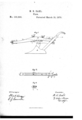
- Figure l is a side cleva- -tion; Fig. 2, a horizontalsection on the line w a; of Fig. 1 and Fig. 3 a crossvsection on the line z z of Fig. 1, looking upward.
- the beam B Iplace on these standards, and pass a bolt, C, up through the rearstandard and the beam, and fasten it by means of a thumb-nut, CZ, so that the beam may turn or swivel on this bolt, as hereinafter described.
- A one or more teeth on one side of its head corresponding in size with the notches n on the rear side of the transverse slot m, as shown in Fig. 3, and pass it up through the slot m in the forward standard and the beam, and
- Vthe beam B I shape so as to iit smoothly against the front side of the handle C, and provide it with a plate, t', having teeth ,1J on its rear end, and to the handle C secure on its front side a plate, j, with grooves 0r indentations q on its outer side, to correspond with the teeth p on the end of the plate i, and on the rear side of-the handle a plate 7c.
- the rear end of the beam and the plate i are provided with a slot, Z, as clearly shown in Fig. 2.
- a plow having its beam B connected to two standards, a b, and to handle C by bolts c, e, and g, in qsuch a manner that it may be turned on the standard a and be adjusted and locked to the standard b and handle C, as herein described, and for thel purpose set forth.
- the plate i provided with the slot Z and l the serrations at its rear end, in combination and 'arranged as herein described, and for the, with the serrated plate j, and bolt g, with its purpose set forth.
Landscapes
- Life Sciences & Earth Sciences (AREA)
- Engineering & Computer Science (AREA)
- Mechanical Engineering (AREA)
- Soil Sciences (AREA)
- Environmental Sciences (AREA)
- Soil Working Implements (AREA)
Description
y 1"@ @ZZ whom `it may concern @PATENT I @maca M; n. DAHL, or WAUPUN, wisconsin.
IMPROVEMENT IN FLOWS.
Specification forming part oi' Leiters Patent No. lldf), dated March 1.,", 1870.
Be itknown that I, M. K. DAHL, of Vaupun, in the county of Fond du Lac and State of Visconsin, have invented certain new and useful Improvements in Flows 5 and I do hereby declarethat the following is a full, clear, and exact description thereof, reference being had Vto the Aaccompanying drawings, making part of this speciicatiomand to the letters of reference marked thereon, like letters indicating like parts wherever they occur.
To enable others skilled in the art to con- Ystruct and use my inyention I will proceed to describe it. y
My invention relates to plows; and it consists ina novel. manner of connecting the beam to the standards and handle for the purpose of allowing it to be adjusted horizontally and securely locked in position when so adjusted;
In the drawings, Figure l is a side cleva- -tion; Fig. 2, a horizontalsection on the line w a; of Fig. 1 and Fig. 3 a crossvsection on the line z z of Fig. 1, looking upward.
In the construction of plows it is often very desirable to changethe direction of the beam in relation to that of the plow proper, so as to throw the share to t-he landside or in the opposite direction. This I accomplish by4 my peculiar manner of connecting the beam, and in such a way that all the parts can -be rigidly locked together at .each adjustment.
I construct my plow A with its beam B and handle C in the usual form, as shownV in Fig. l, and provide it with two standards, a and b, and each of these standards with a fiat head-plate. The head-plate o of the forward standard I form with a transverse slot, m, having its `rear side provided with a series of notches or teeth, n, as clearly shown in Fig.
3; The beam B, Iplace on these standards, and pass a bolt, C, up through the rearstandard and the beam, and fasten it by means of a thumb-nut, CZ, so that the beam may turn or swivel on this bolt, as hereinafter described.A one or more teeth on one side of its head corresponding in size with the notches n on the rear side of the transverse slot m, as shown in Fig. 3, and pass it up through the slot m in the forward standard and the beam, and
I then provide a bolt, e, having fasten it by mea-ns ofthe thumb-"nut f, as
clearly shown in Fig. l. The rear end of Vthe beam B, I shape so as to iit smoothly against the front side of the handle C, and provide it with a plate, t', having teeth ,1J on its rear end, and to the handle C secure on its front side a plate, j, with grooves 0r indentations q on its outer side, to correspond with the teeth p on the end of the plate i, and on the rear side of-the handle a plate 7c. The rear end of the beam and the plate i are provided with a slot, Z, as clearly shown in Fig. 2. Through this slot Z and the handle C, I pass a bolt, g, and lock it with a thumb-nut, h, on the under side, as shown in Fig. 1. When the beam B is thus arranged and connected to the standards and the handle, it may be readily adjusted, as desired, by simply releasing it when fixed by loosening the nuts f and It, and then turning it on the bolt C. As socn as it isturned either to the right or left to the desired position, it can then be securely locked by turning the nuts f and h.
As the nut j' is turned, the tooth. or teethon the side of the head of the bolt e engage with those on the rear side of the slot m, as shown in Fig. 3, and as the nut It is turned the teeth on the end of the plate engage with those on the plate j, as shown in Fig. 2. It will be noticed, also, that as the distance from therear standard, a, to which the beam B is pivoted, is much greater to the front end of the beam than it is to the rear end; that the front end will move through much the largest are of a circle, and that by moving thebeam the plowshare may be thrown to land or in the opposite direction, as desired; and it will be also noticed that this construction admits of a movement ofthe beam, so asto accommodate any number of horses, and
thus obviatethe necessity of using three-horse clevises.
Having thus described my invention, what I claim is- 1. A plow having its beam B connected to two standards, a b, and to handle C by bolts c, e, and g, in qsuch a manner that it may be turned on the standard a and be adjusted and locked to the standard b and handle C, as herein described, and for thel purpose set forth.
The plate i, provided with the slot Z and l the serrations at its rear end, in combination and 'arranged as herein described, and for the, with the serrated plate j, and bolt g, with its purpose set forth.
nut h, when the same are arranged as herein described )L K. DAHL.
3. The combination ofthe standard b, hzws Vtnesses:
ing slot i, with its rear side toothed, with the A. NUDD,
bolt e, beam B, and nut f, when constructed l P. DONOVAN,
Publications (1)
| Publication Number | Publication Date |
|---|---|
| US100869A true US100869A (en) | 1870-03-15 |
Family
ID=2170335
Family Applications (1)
| Application Number | Title | Priority Date | Filing Date |
|---|---|---|---|
| US100869D Expired - Lifetime US100869A (en) | op waupuf |
Country Status (1)
| Country | Link |
|---|---|
| US (1) | US100869A (en) |
-
0
- US US100869D patent/US100869A/en not_active Expired - Lifetime
Similar Documents
| Publication | Publication Date | Title |
|---|---|---|
| US100869A (en) | op waupuf | |
| US105134A (en) | Thomas sheehan | |
| US108329A (en) | Improvement in subsoil-plows | |
| US105570A (en) | Improvement in shovel-teeth for cultivators | |
| US108857A (en) | Improvement in corn-plows | |
| US74348A (en) | of la salle | |
| US107777A (en) | Improvement in cultivators | |
| US108047A (en) | Improvement in shovel-plows | |
| US108516A (en) | Improvement in gang-plows | |
| US87060A (en) | Improvement in horse-hoes | |
| US105326A (en) | Improvement in cotton-cultivators | |
| US283236A (en) | green | |
| US73158A (en) | William bennett | |
| US175251A (en) | Improvement in corn-plows | |
| US121582A (en) | Improvement in plows | |
| US107037A (en) | Improvement in plows | |
| US125572A (en) | Improvement in rotary harrows | |
| US76275A (en) | Tuttle | |
| US108979A (en) | Improvement in plows | |
| US68393A (en) | William h | |
| US117801A (en) | Improvement in plows | |
| US102201A (en) | Improvement in cultivators | |
| US114221A (en) | Improvement in plows | |
| US117149A (en) | Improvement in harrows | |
| US99236A (en) | Improved pulverizing attachment for plows |