US10086365B2 - Strengthened iron catalyst for slurry reactors - Google Patents
Strengthened iron catalyst for slurry reactors Download PDFInfo
- Publication number
- US10086365B2 US10086365B2 US12/198,459 US19845908A US10086365B2 US 10086365 B2 US10086365 B2 US 10086365B2 US 19845908 A US19845908 A US 19845908A US 10086365 B2 US10086365 B2 US 10086365B2
- Authority
- US
- United States
- Prior art keywords
- catalyst
- iron
- solution
- precursor
- sio
- Prior art date
- Legal status (The legal status is an assumption and is not a legal conclusion. Google has not performed a legal analysis and makes no representation as to the accuracy of the status listed.)
- Active - Reinstated
Links
- 239000003054 catalyst Substances 0.000 title claims abstract description 368
- XEEYBQQBJWHFJM-UHFFFAOYSA-N Iron Chemical compound [Fe] XEEYBQQBJWHFJM-UHFFFAOYSA-N 0.000 title claims abstract description 262
- 229910052742 iron Inorganic materials 0.000 title claims abstract description 109
- 239000002002 slurry Substances 0.000 title claims description 71
- 238000000034 method Methods 0.000 claims abstract description 100
- 239000010949 copper Substances 0.000 claims abstract description 83
- 239000012018 catalyst precursor Substances 0.000 claims abstract description 52
- RYGMFSIKBFXOCR-UHFFFAOYSA-N Copper Chemical compound [Cu] RYGMFSIKBFXOCR-UHFFFAOYSA-N 0.000 claims abstract description 46
- 229910052802 copper Inorganic materials 0.000 claims abstract description 46
- 239000011777 magnesium Substances 0.000 claims abstract description 31
- 238000001354 calcination Methods 0.000 claims abstract description 30
- 229910052700 potassium Inorganic materials 0.000 claims abstract description 30
- ZLMJMSJWJFRBEC-UHFFFAOYSA-N Potassium Chemical compound [K] ZLMJMSJWJFRBEC-UHFFFAOYSA-N 0.000 claims abstract description 29
- 239000011591 potassium Substances 0.000 claims abstract description 29
- 229910052749 magnesium Inorganic materials 0.000 claims abstract description 28
- FYYHWMGAXLPEAU-UHFFFAOYSA-N Magnesium Chemical compound [Mg] FYYHWMGAXLPEAU-UHFFFAOYSA-N 0.000 claims abstract description 23
- 229910052782 aluminium Inorganic materials 0.000 claims abstract description 18
- 238000001035 drying Methods 0.000 claims abstract description 17
- XAGFODPZIPBFFR-UHFFFAOYSA-N aluminium Chemical compound [Al] XAGFODPZIPBFFR-UHFFFAOYSA-N 0.000 claims abstract description 16
- 230000001376 precipitating effect Effects 0.000 claims abstract description 16
- 239000002243 precursor Substances 0.000 claims abstract description 11
- VYPSYNLAJGMNEJ-UHFFFAOYSA-N Silicium dioxide Chemical compound O=[Si]=O VYPSYNLAJGMNEJ-UHFFFAOYSA-N 0.000 claims description 264
- 239000000377 silicon dioxide Substances 0.000 claims description 119
- 239000000243 solution Substances 0.000 claims description 101
- 229910052681 coesite Inorganic materials 0.000 claims description 68
- 229910052906 cristobalite Inorganic materials 0.000 claims description 68
- 229910052682 stishovite Inorganic materials 0.000 claims description 68
- 229910052905 tridymite Inorganic materials 0.000 claims description 68
- BWHMMNNQKKPAPP-UHFFFAOYSA-L potassium carbonate Chemical compound [K+].[K+].[O-]C([O-])=O BWHMMNNQKKPAPP-UHFFFAOYSA-L 0.000 claims description 58
- 239000004111 Potassium silicate Substances 0.000 claims description 46
- NNHHDJVEYQHLHG-UHFFFAOYSA-N potassium silicate Chemical compound [K+].[K+].[O-][Si]([O-])=O NNHHDJVEYQHLHG-UHFFFAOYSA-N 0.000 claims description 46
- 235000019353 potassium silicate Nutrition 0.000 claims description 46
- 229910052913 potassium silicate Inorganic materials 0.000 claims description 46
- GRYLNZFGIOXLOG-UHFFFAOYSA-N Nitric acid Chemical compound O[N+]([O-])=O GRYLNZFGIOXLOG-UHFFFAOYSA-N 0.000 claims description 32
- 229910017604 nitric acid Inorganic materials 0.000 claims description 32
- 229910000027 potassium carbonate Inorganic materials 0.000 claims description 29
- 239000002253 acid Substances 0.000 claims description 28
- CDBYLPFSWZWCQE-UHFFFAOYSA-L Sodium Carbonate Chemical compound [Na+].[Na+].[O-]C([O-])=O CDBYLPFSWZWCQE-UHFFFAOYSA-L 0.000 claims description 26
- VHUUQVKOLVNVRT-UHFFFAOYSA-N Ammonium hydroxide Chemical compound [NH4+].[OH-] VHUUQVKOLVNVRT-UHFFFAOYSA-N 0.000 claims description 25
- BOTDANWDWHJENH-UHFFFAOYSA-N Tetraethyl orthosilicate Chemical compound CCO[Si](OCC)(OCC)OCC BOTDANWDWHJENH-UHFFFAOYSA-N 0.000 claims description 22
- 239000000908 ammonium hydroxide Substances 0.000 claims description 21
- 238000001556 precipitation Methods 0.000 claims description 21
- 239000007864 aqueous solution Substances 0.000 claims description 20
- 238000001694 spray drying Methods 0.000 claims description 20
- XTVVROIMIGLXTD-UHFFFAOYSA-N copper(II) nitrate Chemical compound [Cu+2].[O-][N+]([O-])=O.[O-][N+]([O-])=O XTVVROIMIGLXTD-UHFFFAOYSA-N 0.000 claims description 15
- 238000002156 mixing Methods 0.000 claims description 13
- 229910000029 sodium carbonate Inorganic materials 0.000 claims description 13
- RMAQACBXLXPBSY-UHFFFAOYSA-N silicic acid Chemical compound O[Si](O)(O)O RMAQACBXLXPBSY-UHFFFAOYSA-N 0.000 claims description 12
- 239000008119 colloidal silica Substances 0.000 claims description 11
- AZDRQVAHHNSJOQ-UHFFFAOYSA-N alumane Chemical class [AlH3] AZDRQVAHHNSJOQ-UHFFFAOYSA-N 0.000 claims description 9
- RAQDACVRFCEPDA-UHFFFAOYSA-L ferrous carbonate Chemical class [Fe+2].[O-]C([O-])=O RAQDACVRFCEPDA-UHFFFAOYSA-L 0.000 claims description 6
- 235000014413 iron hydroxide Nutrition 0.000 claims description 6
- NCNCGGDMXMBVIA-UHFFFAOYSA-L iron(ii) hydroxide Chemical class [OH-].[OH-].[Fe+2] NCNCGGDMXMBVIA-UHFFFAOYSA-L 0.000 claims description 6
- 150000002823 nitrates Chemical class 0.000 claims description 6
- CWYNVVGOOAEACU-UHFFFAOYSA-N Fe2+ Chemical compound [Fe+2] CWYNVVGOOAEACU-UHFFFAOYSA-N 0.000 claims description 4
- YIXJRHPUWRPCBB-UHFFFAOYSA-N magnesium nitrate Chemical compound [Mg+2].[O-][N+]([O-])=O.[O-][N+]([O-])=O YIXJRHPUWRPCBB-UHFFFAOYSA-N 0.000 claims description 4
- QPLDLSVMHZLSFG-UHFFFAOYSA-N Copper oxide Chemical compound [Cu]=O QPLDLSVMHZLSFG-UHFFFAOYSA-N 0.000 claims description 2
- 239000005751 Copper oxide Substances 0.000 claims description 2
- JLDSOYXADOWAKB-UHFFFAOYSA-N aluminium nitrate Chemical class [Al+3].[O-][N+]([O-])=O.[O-][N+]([O-])=O.[O-][N+]([O-])=O JLDSOYXADOWAKB-UHFFFAOYSA-N 0.000 claims description 2
- 229910000431 copper oxide Inorganic materials 0.000 claims description 2
- 150000001879 copper Chemical class 0.000 claims 7
- 150000002505 iron Chemical class 0.000 claims 7
- 159000000003 magnesium salts Chemical class 0.000 claims 7
- 230000001737 promoting effect Effects 0.000 claims 1
- 150000003839 salts Chemical class 0.000 claims 1
- 239000000203 mixture Substances 0.000 abstract description 55
- 239000002244 precipitate Substances 0.000 abstract description 29
- 229910002091 carbon monoxide Inorganic materials 0.000 abstract description 20
- -1 oxides Chemical class 0.000 abstract description 15
- 238000005406 washing Methods 0.000 abstract description 15
- UGFAIRIUMAVXCW-UHFFFAOYSA-N Carbon monoxide Chemical compound [O+]#[C-] UGFAIRIUMAVXCW-UHFFFAOYSA-N 0.000 abstract description 11
- 238000005728 strengthening Methods 0.000 abstract description 4
- 230000003113 alkalizing effect Effects 0.000 abstract description 2
- 150000004649 carbonic acid derivatives Chemical class 0.000 abstract 1
- 150000004679 hydroxides Chemical class 0.000 abstract 1
- XLYOFNOQVPJJNP-UHFFFAOYSA-N water Substances O XLYOFNOQVPJJNP-UHFFFAOYSA-N 0.000 description 108
- 230000004913 activation Effects 0.000 description 55
- 238000006243 chemical reaction Methods 0.000 description 52
- 239000008367 deionised water Substances 0.000 description 49
- 229910021641 deionized water Inorganic materials 0.000 description 49
- 239000002245 particle Substances 0.000 description 47
- 238000012360 testing method Methods 0.000 description 45
- 239000001993 wax Substances 0.000 description 42
- 230000000694 effects Effects 0.000 description 41
- 229910001868 water Inorganic materials 0.000 description 41
- 239000000463 material Substances 0.000 description 35
- 229930195733 hydrocarbon Natural products 0.000 description 27
- 150000002430 hydrocarbons Chemical class 0.000 description 27
- 230000015572 biosynthetic process Effects 0.000 description 23
- 239000007789 gas Substances 0.000 description 21
- 239000007788 liquid Substances 0.000 description 20
- VNWKTOKETHGBQD-UHFFFAOYSA-N methane Chemical compound C VNWKTOKETHGBQD-UHFFFAOYSA-N 0.000 description 19
- 238000000975 co-precipitation Methods 0.000 description 18
- 238000003786 synthesis reaction Methods 0.000 description 18
- 229910002651 NO3 Inorganic materials 0.000 description 17
- NHNBFGGVMKEFGY-UHFFFAOYSA-N Nitrate Chemical compound [O-][N+]([O-])=O NHNBFGGVMKEFGY-UHFFFAOYSA-N 0.000 description 17
- 238000002474 experimental method Methods 0.000 description 17
- UQSXHKLRYXJYBZ-UHFFFAOYSA-N iron oxide Inorganic materials [Fe]=O UQSXHKLRYXJYBZ-UHFFFAOYSA-N 0.000 description 17
- 238000002360 preparation method Methods 0.000 description 16
- 238000000926 separation method Methods 0.000 description 16
- 239000007787 solid Substances 0.000 description 16
- 239000007921 spray Substances 0.000 description 16
- 229910052751 metal Inorganic materials 0.000 description 15
- 239000002184 metal Substances 0.000 description 15
- 239000000047 product Substances 0.000 description 15
- 239000004215 Carbon black (E152) Substances 0.000 description 14
- 230000001965 increasing effect Effects 0.000 description 14
- 238000009826 distribution Methods 0.000 description 13
- 239000001257 hydrogen Substances 0.000 description 13
- 229910052739 hydrogen Inorganic materials 0.000 description 13
- 239000011230 binding agent Substances 0.000 description 12
- MWUXSHHQAYIFBG-UHFFFAOYSA-N nitrogen oxide Inorganic materials O=[N] MWUXSHHQAYIFBG-UHFFFAOYSA-N 0.000 description 12
- IJGRMHOSHXDMSA-UHFFFAOYSA-N Atomic nitrogen Chemical compound N#N IJGRMHOSHXDMSA-UHFFFAOYSA-N 0.000 description 11
- 238000010438 heat treatment Methods 0.000 description 11
- 235000013980 iron oxide Nutrition 0.000 description 11
- 238000003756 stirring Methods 0.000 description 11
- UFHFLCQGNIYNRP-UHFFFAOYSA-N Hydrogen Chemical compound [H][H] UFHFLCQGNIYNRP-UHFFFAOYSA-N 0.000 description 10
- 239000003153 chemical reaction reagent Substances 0.000 description 10
- 239000003921 oil Substances 0.000 description 10
- CURLTUGMZLYLDI-UHFFFAOYSA-N Carbon dioxide Chemical compound O=C=O CURLTUGMZLYLDI-UHFFFAOYSA-N 0.000 description 9
- 229910002092 carbon dioxide Inorganic materials 0.000 description 9
- 150000002739 metals Chemical class 0.000 description 9
- 230000008569 process Effects 0.000 description 9
- 229910052596 spinel Inorganic materials 0.000 description 9
- 229910026161 MgAl2O4 Inorganic materials 0.000 description 8
- PNEYBMLMFCGWSK-UHFFFAOYSA-N aluminium oxide Inorganic materials [O-2].[O-2].[O-2].[Al+3].[Al+3] PNEYBMLMFCGWSK-UHFFFAOYSA-N 0.000 description 8
- 230000003197 catalytic effect Effects 0.000 description 8
- 230000001186 cumulative effect Effects 0.000 description 8
- 238000005470 impregnation Methods 0.000 description 8
- 239000000843 powder Substances 0.000 description 8
- 239000011541 reaction mixture Substances 0.000 description 8
- BPQQTUXANYXVAA-UHFFFAOYSA-N Orthosilicate Chemical compound [O-][Si]([O-])([O-])[O-] BPQQTUXANYXVAA-UHFFFAOYSA-N 0.000 description 7
- 239000000706 filtrate Substances 0.000 description 7
- 238000001914 filtration Methods 0.000 description 7
- VCJMYUPGQJHHFU-UHFFFAOYSA-N iron(3+);trinitrate Chemical compound [Fe+3].[O-][N+]([O-])=O.[O-][N+]([O-])=O.[O-][N+]([O-])=O VCJMYUPGQJHHFU-UHFFFAOYSA-N 0.000 description 7
- 229910044991 metal oxide Inorganic materials 0.000 description 7
- 150000004706 metal oxides Chemical class 0.000 description 7
- OCKGFTQIICXDQW-ZEQRLZLVSA-N 5-[(1r)-1-hydroxy-2-[4-[(2r)-2-hydroxy-2-(4-methyl-1-oxo-3h-2-benzofuran-5-yl)ethyl]piperazin-1-yl]ethyl]-4-methyl-3h-2-benzofuran-1-one Chemical compound C1=C2C(=O)OCC2=C(C)C([C@@H](O)CN2CCN(CC2)C[C@H](O)C2=CC=C3C(=O)OCC3=C2C)=C1 OCKGFTQIICXDQW-ZEQRLZLVSA-N 0.000 description 6
- OKTJSMMVPCPJKN-UHFFFAOYSA-N Carbon Chemical compound [C] OKTJSMMVPCPJKN-UHFFFAOYSA-N 0.000 description 6
- 229910052799 carbon Inorganic materials 0.000 description 6
- 229910052593 corundum Inorganic materials 0.000 description 6
- 238000005516 engineering process Methods 0.000 description 6
- IQKLAEINENLGAG-UHFFFAOYSA-N iron oxocopper Chemical compound [Fe].[Cu]=O IQKLAEINENLGAG-UHFFFAOYSA-N 0.000 description 6
- 230000007774 longterm Effects 0.000 description 6
- 238000004519 manufacturing process Methods 0.000 description 6
- 229910052710 silicon Inorganic materials 0.000 description 6
- 239000000126 substance Substances 0.000 description 6
- 229910001845 yogo sapphire Inorganic materials 0.000 description 6
- PAWQVTBBRAZDMG-UHFFFAOYSA-N 2-(3-bromo-2-fluorophenyl)acetic acid Chemical compound OC(=O)CC1=CC=CC(Br)=C1F PAWQVTBBRAZDMG-UHFFFAOYSA-N 0.000 description 5
- CPLXHLVBOLITMK-UHFFFAOYSA-N Magnesium oxide Chemical compound [Mg]=O CPLXHLVBOLITMK-UHFFFAOYSA-N 0.000 description 5
- XUIMIQQOPSSXEZ-UHFFFAOYSA-N Silicon Chemical compound [Si] XUIMIQQOPSSXEZ-UHFFFAOYSA-N 0.000 description 5
- 238000001816 cooling Methods 0.000 description 5
- 230000007423 decrease Effects 0.000 description 5
- VBMVTYDPPZVILR-UHFFFAOYSA-N iron(2+);oxygen(2-) Chemical class [O-2].[Fe+2] VBMVTYDPPZVILR-UHFFFAOYSA-N 0.000 description 5
- 238000010907 mechanical stirring Methods 0.000 description 5
- 239000004005 microsphere Substances 0.000 description 5
- 229910052757 nitrogen Inorganic materials 0.000 description 5
- JCXJVPUVTGWSNB-UHFFFAOYSA-N nitrogen dioxide Inorganic materials O=[N]=O JCXJVPUVTGWSNB-UHFFFAOYSA-N 0.000 description 5
- 239000010703 silicon Substances 0.000 description 5
- MGWGWNFMUOTEHG-UHFFFAOYSA-N 4-(3,5-dimethylphenyl)-1,3-thiazol-2-amine Chemical compound CC1=CC(C)=CC(C=2N=C(N)SC=2)=C1 MGWGWNFMUOTEHG-UHFFFAOYSA-N 0.000 description 4
- QGZKDVFQNNGYKY-UHFFFAOYSA-N Ammonia Chemical compound N QGZKDVFQNNGYKY-UHFFFAOYSA-N 0.000 description 4
- KWYUFKZDYYNOTN-UHFFFAOYSA-M Potassium hydroxide Chemical compound [OH-].[K+] KWYUFKZDYYNOTN-UHFFFAOYSA-M 0.000 description 4
- QPPSCXPWECCHRD-UHFFFAOYSA-N [N+](=O)([O-])[O-].[Cu+2].[Fe+2].[N+](=O)([O-])[O-].[N+](=O)([O-])[O-].[N+](=O)([O-])[O-] Chemical compound [N+](=O)([O-])[O-].[Cu+2].[Fe+2].[N+](=O)([O-])[O-].[N+](=O)([O-])[O-].[N+](=O)([O-])[O-] QPPSCXPWECCHRD-UHFFFAOYSA-N 0.000 description 4
- QVGXLLKOCUKJST-UHFFFAOYSA-N atomic oxygen Chemical compound [O] QVGXLLKOCUKJST-UHFFFAOYSA-N 0.000 description 4
- 230000015556 catabolic process Effects 0.000 description 4
- 238000011065 in-situ storage Methods 0.000 description 4
- 229910052752 metalloid Inorganic materials 0.000 description 4
- 150000002738 metalloids Chemical class 0.000 description 4
- 239000004570 mortar (masonry) Substances 0.000 description 4
- 230000007935 neutral effect Effects 0.000 description 4
- 229960003753 nitric oxide Drugs 0.000 description 4
- 239000001301 oxygen Substances 0.000 description 4
- 229910052760 oxygen Inorganic materials 0.000 description 4
- VWDWKYIASSYTQR-UHFFFAOYSA-N sodium nitrate Chemical compound [Na+].[O-][N+]([O-])=O VWDWKYIASSYTQR-UHFFFAOYSA-N 0.000 description 4
- 239000000725 suspension Substances 0.000 description 4
- NWUYHJFMYQTDRP-UHFFFAOYSA-N 1,2-bis(ethenyl)benzene;1-ethenyl-2-ethylbenzene;styrene Chemical compound C=CC1=CC=CC=C1.CCC1=CC=CC=C1C=C.C=CC1=CC=CC=C1C=C NWUYHJFMYQTDRP-UHFFFAOYSA-N 0.000 description 3
- 229910000608 Fe(NO3)3.9H2O Inorganic materials 0.000 description 3
- HEMHJVSKTPXQMS-UHFFFAOYSA-M Sodium hydroxide Chemical compound [OH-].[Na+] HEMHJVSKTPXQMS-UHFFFAOYSA-M 0.000 description 3
- 230000009471 action Effects 0.000 description 3
- 230000003213 activating effect Effects 0.000 description 3
- 150000001336 alkenes Chemical class 0.000 description 3
- 230000008901 benefit Effects 0.000 description 3
- 239000007795 chemical reaction product Substances 0.000 description 3
- IYRDVAUFQZOLSB-UHFFFAOYSA-N copper iron Chemical compound [Fe].[Cu] IYRDVAUFQZOLSB-UHFFFAOYSA-N 0.000 description 3
- 238000000151 deposition Methods 0.000 description 3
- 238000004090 dissolution Methods 0.000 description 3
- SZVJSHCCFOBDDC-UHFFFAOYSA-N ferrosoferric oxide Chemical compound O=[Fe]O[Fe]O[Fe]=O SZVJSHCCFOBDDC-UHFFFAOYSA-N 0.000 description 3
- 239000005457 ice water Substances 0.000 description 3
- 239000003456 ion exchange resin Substances 0.000 description 3
- 229920003303 ion-exchange polymer Polymers 0.000 description 3
- 239000000395 magnesium oxide Substances 0.000 description 3
- 238000006116 polymerization reaction Methods 0.000 description 3
- 230000035882 stress Effects 0.000 description 3
- QEMXHQIAXOOASZ-UHFFFAOYSA-N tetramethylammonium Chemical compound C[N+](C)(C)C QEMXHQIAXOOASZ-UHFFFAOYSA-N 0.000 description 3
- ZAMOUSCENKQFHK-UHFFFAOYSA-N Chlorine atom Chemical compound [Cl] ZAMOUSCENKQFHK-UHFFFAOYSA-N 0.000 description 2
- VEXZGXHMUGYJMC-UHFFFAOYSA-N Hydrochloric acid Chemical compound Cl VEXZGXHMUGYJMC-UHFFFAOYSA-N 0.000 description 2
- UIIMBOGNXHQVGW-UHFFFAOYSA-M Sodium bicarbonate Chemical compound [Na+].OC([O-])=O UIIMBOGNXHQVGW-UHFFFAOYSA-M 0.000 description 2
- GWEVSGVZZGPLCZ-UHFFFAOYSA-N Titan oxide Chemical compound O=[Ti]=O GWEVSGVZZGPLCZ-UHFFFAOYSA-N 0.000 description 2
- 229910001567 cementite Inorganic materials 0.000 description 2
- 230000008859 change Effects 0.000 description 2
- 239000000460 chlorine Substances 0.000 description 2
- 229910052801 chlorine Inorganic materials 0.000 description 2
- 230000006690 co-activation Effects 0.000 description 2
- 150000001875 compounds Chemical class 0.000 description 2
- 230000000875 corresponding effect Effects 0.000 description 2
- 230000009849 deactivation Effects 0.000 description 2
- 230000003247 decreasing effect Effects 0.000 description 2
- 150000002431 hydrogen Chemical class 0.000 description 2
- 239000011261 inert gas Substances 0.000 description 2
- 238000012986 modification Methods 0.000 description 2
- 230000004048 modification Effects 0.000 description 2
- 238000012544 monitoring process Methods 0.000 description 2
- JRZJOMJEPLMPRA-UHFFFAOYSA-N olefin Natural products CCCCCCCC=C JRZJOMJEPLMPRA-UHFFFAOYSA-N 0.000 description 2
- 239000012188 paraffin wax Substances 0.000 description 2
- 239000011148 porous material Substances 0.000 description 2
- 230000009467 reduction Effects 0.000 description 2
- 238000006722 reduction reaction Methods 0.000 description 2
- 239000011347 resin Substances 0.000 description 2
- 229920005989 resin Polymers 0.000 description 2
- 239000004317 sodium nitrate Substances 0.000 description 2
- 235000010344 sodium nitrate Nutrition 0.000 description 2
- 239000007858 starting material Substances 0.000 description 2
- RLQWHDODQVOVKU-UHFFFAOYSA-N tetrapotassium;silicate Chemical compound [K+].[K+].[K+].[K+].[O-][Si]([O-])([O-])[O-] RLQWHDODQVOVKU-UHFFFAOYSA-N 0.000 description 2
- 230000009466 transformation Effects 0.000 description 2
- BNGXYYYYKUGPPF-UHFFFAOYSA-M (3-methylphenyl)methyl-triphenylphosphanium;chloride Chemical compound [Cl-].CC1=CC=CC(C[P+](C=2C=CC=CC=2)(C=2C=CC=CC=2)C=2C=CC=CC=2)=C1 BNGXYYYYKUGPPF-UHFFFAOYSA-M 0.000 description 1
- 238000010744 Boudouard reaction Methods 0.000 description 1
- 229910018576 CuAl2O4 Inorganic materials 0.000 description 1
- PMVSDNDAUGGCCE-TYYBGVCCSA-L Ferrous fumarate Chemical compound [Fe+2].[O-]C(=O)\C=C\C([O-])=O PMVSDNDAUGGCCE-TYYBGVCCSA-L 0.000 description 1
- 208000033962 Fontaine progeroid syndrome Diseases 0.000 description 1
- 239000004743 Polypropylene Substances 0.000 description 1
- 150000007513 acids Chemical class 0.000 description 1
- 230000032683 aging Effects 0.000 description 1
- 150000001298 alcohols Chemical class 0.000 description 1
- 150000001335 aliphatic alkanes Chemical class 0.000 description 1
- 229910021529 ammonia Inorganic materials 0.000 description 1
- 238000013459 approach Methods 0.000 description 1
- 238000004380 ashing Methods 0.000 description 1
- 238000011021 bench scale process Methods 0.000 description 1
- 239000000872 buffer Substances 0.000 description 1
- 239000001569 carbon dioxide Substances 0.000 description 1
- 238000004517 catalytic hydrocracking Methods 0.000 description 1
- 239000003795 chemical substances by application Substances 0.000 description 1
- 239000003426 co-catalyst Substances 0.000 description 1
- 239000003245 coal Substances 0.000 description 1
- 230000000052 comparative effect Effects 0.000 description 1
- 230000002596 correlated effect Effects 0.000 description 1
- 230000002939 deleterious effect Effects 0.000 description 1
- 230000008021 deposition Effects 0.000 description 1
- 238000013461 design Methods 0.000 description 1
- 230000001627 detrimental effect Effects 0.000 description 1
- 238000011161 development Methods 0.000 description 1
- 230000018109 developmental process Effects 0.000 description 1
- IZDJJEMZQZQQQQ-UHFFFAOYSA-N dicopper;tetranitrate;pentahydrate Chemical compound O.O.O.O.O.[Cu+2].[Cu+2].[O-][N+]([O-])=O.[O-][N+]([O-])=O.[O-][N+]([O-])=O.[O-][N+]([O-])=O IZDJJEMZQZQQQQ-UHFFFAOYSA-N 0.000 description 1
- 238000007865 diluting Methods 0.000 description 1
- 239000006185 dispersion Substances 0.000 description 1
- 238000011066 ex-situ storage Methods 0.000 description 1
- 239000012530 fluid Substances 0.000 description 1
- 238000002290 gas chromatography-mass spectrometry Methods 0.000 description 1
- 229910052595 hematite Inorganic materials 0.000 description 1
- 239000011019 hematite Substances 0.000 description 1
- 239000002638 heterogeneous catalyst Substances 0.000 description 1
- 125000004435 hydrogen atom Chemical group [H]* 0.000 description 1
- 230000006872 improvement Effects 0.000 description 1
- 230000001939 inductive effect Effects 0.000 description 1
- 239000004615 ingredient Substances 0.000 description 1
- 239000003999 initiator Substances 0.000 description 1
- LIKBJVNGSGBSGK-UHFFFAOYSA-N iron(3+);oxygen(2-) Chemical compound [O-2].[O-2].[O-2].[Fe+3].[Fe+3] LIKBJVNGSGBSGK-UHFFFAOYSA-N 0.000 description 1
- JEIPFZHSYJVQDO-UHFFFAOYSA-N iron(III) oxide Inorganic materials O=[Fe]O[Fe]=O JEIPFZHSYJVQDO-UHFFFAOYSA-N 0.000 description 1
- 239000012263 liquid product Substances 0.000 description 1
- AXZKOIWUVFPNLO-UHFFFAOYSA-N magnesium;oxygen(2-) Chemical compound [O-2].[Mg+2] AXZKOIWUVFPNLO-UHFFFAOYSA-N 0.000 description 1
- 230000014759 maintenance of location Effects 0.000 description 1
- 229910001960 metal nitrate Inorganic materials 0.000 description 1
- 125000002496 methyl group Chemical group [H]C([H])([H])* 0.000 description 1
- 229910003455 mixed metal oxide Inorganic materials 0.000 description 1
- 239000003345 natural gas Substances 0.000 description 1
- 230000000704 physical effect Effects 0.000 description 1
- 229920001467 poly(styrenesulfonates) Polymers 0.000 description 1
- 238000012643 polycondensation polymerization Methods 0.000 description 1
- 229920001155 polypropylene Polymers 0.000 description 1
- 229910052573 porcelain Inorganic materials 0.000 description 1
- 239000011736 potassium bicarbonate Substances 0.000 description 1
- 229910000028 potassium bicarbonate Inorganic materials 0.000 description 1
- TYJJADVDDVDEDZ-UHFFFAOYSA-M potassium hydrogencarbonate Chemical compound [K+].OC([O-])=O TYJJADVDDVDEDZ-UHFFFAOYSA-M 0.000 description 1
- 238000002203 pretreatment Methods 0.000 description 1
- 239000002994 raw material Substances 0.000 description 1
- 238000011160 research Methods 0.000 description 1
- 238000010008 shearing Methods 0.000 description 1
- 239000000741 silica gel Substances 0.000 description 1
- 229910002027 silica gel Inorganic materials 0.000 description 1
- 229910000030 sodium bicarbonate Inorganic materials 0.000 description 1
- 239000011949 solid catalyst Substances 0.000 description 1
- 238000001228 spectrum Methods 0.000 description 1
- 239000011029 spinel Substances 0.000 description 1
- 229910001220 stainless steel Inorganic materials 0.000 description 1
- 239000010935 stainless steel Substances 0.000 description 1
- 238000000844 transformation Methods 0.000 description 1
- 238000011144 upstream manufacturing Methods 0.000 description 1
Images


Classifications
-
- B—PERFORMING OPERATIONS; TRANSPORTING
- B01—PHYSICAL OR CHEMICAL PROCESSES OR APPARATUS IN GENERAL
- B01J—CHEMICAL OR PHYSICAL PROCESSES, e.g. CATALYSIS OR COLLOID CHEMISTRY; THEIR RELEVANT APPARATUS
- B01J23/00—Catalysts comprising metals or metal oxides or hydroxides, not provided for in group B01J21/00
- B01J23/70—Catalysts comprising metals or metal oxides or hydroxides, not provided for in group B01J21/00 of the iron group metals or copper
- B01J23/76—Catalysts comprising metals or metal oxides or hydroxides, not provided for in group B01J21/00 of the iron group metals or copper combined with metals, oxides or hydroxides provided for in groups B01J23/02 - B01J23/36
- B01J23/78—Catalysts comprising metals or metal oxides or hydroxides, not provided for in group B01J21/00 of the iron group metals or copper combined with metals, oxides or hydroxides provided for in groups B01J23/02 - B01J23/36 with alkali- or alkaline earth metals
-
- B—PERFORMING OPERATIONS; TRANSPORTING
- B01—PHYSICAL OR CHEMICAL PROCESSES OR APPARATUS IN GENERAL
- B01J—CHEMICAL OR PHYSICAL PROCESSES, e.g. CATALYSIS OR COLLOID CHEMISTRY; THEIR RELEVANT APPARATUS
- B01J21/00—Catalysts comprising the elements, oxides, or hydroxides of magnesium, boron, aluminium, carbon, silicon, titanium, zirconium, or hafnium
- B01J21/005—Spinels
-
- B—PERFORMING OPERATIONS; TRANSPORTING
- B01—PHYSICAL OR CHEMICAL PROCESSES OR APPARATUS IN GENERAL
- B01J—CHEMICAL OR PHYSICAL PROCESSES, e.g. CATALYSIS OR COLLOID CHEMISTRY; THEIR RELEVANT APPARATUS
- B01J37/00—Processes, in general, for preparing catalysts; Processes, in general, for activation of catalysts
- B01J37/02—Impregnation, coating or precipitation
- B01J37/03—Precipitation; Co-precipitation
-
- C—CHEMISTRY; METALLURGY
- C10—PETROLEUM, GAS OR COKE INDUSTRIES; TECHNICAL GASES CONTAINING CARBON MONOXIDE; FUELS; LUBRICANTS; PEAT
- C10G—CRACKING HYDROCARBON OILS; PRODUCTION OF LIQUID HYDROCARBON MIXTURES, e.g. BY DESTRUCTIVE HYDROGENATION, OLIGOMERISATION, POLYMERISATION; RECOVERY OF HYDROCARBON OILS FROM OIL-SHALE, OIL-SAND, OR GASES; REFINING MIXTURES MAINLY CONSISTING OF HYDROCARBONS; REFORMING OF NAPHTHA; MINERAL WAXES
- C10G2/00—Production of liquid hydrocarbon mixtures of undefined composition from oxides of carbon
- C10G2/30—Production of liquid hydrocarbon mixtures of undefined composition from oxides of carbon from carbon monoxide with hydrogen
- C10G2/32—Production of liquid hydrocarbon mixtures of undefined composition from oxides of carbon from carbon monoxide with hydrogen with the use of catalysts
- C10G2/33—Production of liquid hydrocarbon mixtures of undefined composition from oxides of carbon from carbon monoxide with hydrogen with the use of catalysts characterised by the catalyst used
- C10G2/331—Production of liquid hydrocarbon mixtures of undefined composition from oxides of carbon from carbon monoxide with hydrogen with the use of catalysts characterised by the catalyst used containing group VIII-metals
-
- B—PERFORMING OPERATIONS; TRANSPORTING
- B01—PHYSICAL OR CHEMICAL PROCESSES OR APPARATUS IN GENERAL
- B01J—CHEMICAL OR PHYSICAL PROCESSES, e.g. CATALYSIS OR COLLOID CHEMISTRY; THEIR RELEVANT APPARATUS
- B01J21/00—Catalysts comprising the elements, oxides, or hydroxides of magnesium, boron, aluminium, carbon, silicon, titanium, zirconium, or hafnium
- B01J21/06—Silicon, titanium, zirconium or hafnium; Oxides or hydroxides thereof
- B01J21/08—Silica
-
- C—CHEMISTRY; METALLURGY
- C10—PETROLEUM, GAS OR COKE INDUSTRIES; TECHNICAL GASES CONTAINING CARBON MONOXIDE; FUELS; LUBRICANTS; PEAT
- C10G—CRACKING HYDROCARBON OILS; PRODUCTION OF LIQUID HYDROCARBON MIXTURES, e.g. BY DESTRUCTIVE HYDROGENATION, OLIGOMERISATION, POLYMERISATION; RECOVERY OF HYDROCARBON OILS FROM OIL-SHALE, OIL-SAND, OR GASES; REFINING MIXTURES MAINLY CONSISTING OF HYDROCARBONS; REFORMING OF NAPHTHA; MINERAL WAXES
- C10G2300/00—Aspects relating to hydrocarbon processing covered by groups C10G1/00 - C10G99/00
- C10G2300/70—Catalyst aspects
Definitions
- the present invention relates generally to an improved catalyst for use in Fischer-Tropsch processes. More particularly, the present invention relates to a method of improving the structural integrity of a Fischer-Tropsch catalyst without losing substantial catalytic activity and selectivity toward heavy hydrocarbons. Still more specifically, the present invention relates to a method of producing a Fischer-Tropsch catalyst containing a structural support such as a binder incorporated after precipitation of the catalyst precursor or a support material coprecipitated with iron. The support material increases the structural integrity of the catalyst.
- the catalyst of the present disclosure may comprise coprecipitated material selected from iron, silica, magnesium, copper, aluminum, and combinations thereof. Alternatively, or additionally, potassium silicate binder, colloidal silica, and/or tetraethyl ortho silicate (TEOS) may be added to a precipitated catalyst to increase the strength thereof.
- TEOS tetraethyl ortho silicate
- the Fischer-Tropsch (FT) technology is used to convert a mixture of hydrogen and carbon monoxide (synthesis gas or syngas) to valuable hydrocarbon products. Often, the process utilizes a slurry bubble column reactor (SBCR).
- SBCR slurry bubble column reactor
- the technology of converting synthesis gas originating from natural gas into valuable primarily liquid hydrocarbon products is referred to as Gas To Liquids (GTL) technology.
- GTL Gas To Liquids
- CTL Coal-To-Liquids
- the FT technology is one of several conversion techniques included in the broader GTL/CTL technology.
- iron catalyst breakdown There are at least three modes of iron catalyst breakdown.
- mechanical action can cause breakup of the particles due to catalyst particles impinging each other or the reactor walls.
- Improved catalyst strength can be achieved by depositing the iron on a refractory support such as silica, alumina or magnesia or by adding a structural promoter to the baseline catalyst.
- the challenge is to strengthen the catalyst without appreciably compromising the activity and selectivity of the catalyst.
- Use of binders, for example, SiO 2 binder has been performed at high levels, e.g. 10%-15%. These catalysts seem to yield very light products.
- Silica (SiO 2 ) and alumina (Al 2 O 3 ) as supports at high levels ( ⁇ 10%) are known.
- a catalyst and a method of making same which has improved resistance against breakdown and also maintains the salient features of an unsupported iron catalyst, viz. high activity and selectivity toward high molecular weight hydrocarbons.
- Such a catalyst should preferably also improve separation of the catalyst from the reaction mixture.
- a method of strengthening a precipitated unsupported iron catalyst by: providing a raw catalyst containing copper and potassium; adding a solution comprising a structural promoter to the catalyst; drying the mixture; and calcining the dried catalyst.
- a strengthened catalyst prepared using the disclosed method.
- the structural promoter may comprise potassium silicate.
- the potassium silicate may be an aqueous solution.
- the weight percent of SiO 2 in the dried catalyst is from about 1% to about 2.2%. In some embodiments, the weight percent of copper in the catalyst is about 1%. In embodiments, the weight percent of potassium in the catalyst is about 1%.
- liquid structural promoter is added via incipient wetness technique.
- the particle size distribution of the strengthened catalyst may be the same as the precipitated unsupported catalyst.
- Also disclosed herein is a method for preparing an iron catalyst, the method comprising: precipitating a catalyst precursor comprising at least one iron phase selected from iron hydroxides and iron carbonates; adding a promoter to the catalyst precursor to yield a promoted precursor; drying the promoted precursor to yield dried catalyst; and calcining the dried catalyst, wherein the catalyst further comprises copper and potassium.
- the method may further comprise adding potassium carbonate to the catalyst precursor in an amount sufficient to promote the catalyst with potassium.
- the catalyst precursor may further comprise copper oxide.
- the method may further comprise adding copper nitrate to the catalyst precursor.
- the promoter may comprise liquid potassium silicate structural promoter.
- the potassium silicate may be an aqueous solution.
- the dried catalyst may comprise from about 1 wt % SiO 2 to about 2.2 wt % SiO 2 .
- the dried catalyst comprises about 1% copper and about 1% potassium.
- the structural promoter comprises TEOS.
- precipitating a catalyst precursor comprises precipitating iron hydroxide, iron carbonate, or a mixture thereof from a solution comprising TEOS or potassium silicate, and adding a promoter to the catalyst precursor to yield a promoted precursor comprises adding potassium carbonate.
- the promoter comprises silica as structural promoter.
- the silica may be in a colloidal form.
- the silica may comprise silica sol.
- the Fe:Cu mass ratio is between about 100:1 and 100:7. In specific embodiments, the Fe:Cu mass ratio is about 100:4. In embodiments of the method for preparing an iron catalyst, the Fe:K mass ratio is between about 100:1 and 100:5. In specific embodiments, the Fe:K mass ratio is about 100:3. In embodiments of the method for preparing an iron catalyst, the Fe:SiO 2 mass ratio is between about 100:1 and 100:8.
- the Fe:SiO 2 mass ratio is about 100:5.
- the Fe:Cu:K:SiO 2 mass ratio may be about 100:4:3:5. In other embodiments, the Fe:Cu:K:SiO 2 mass ratio is about 100:3:3:5.
- Also disclosed herein is a method of preparing a strengthened precipitated iron catalyst comprising: co-precipitating iron, copper, magnesium, and aluminum; washing the precipitate; alkalizing the precipitate; and drying the precipitate to yield a dried catalyst precursor.
- the method of preparing a strengthened precipitated iron catalyst may further comprise calcining the dried catalyst precursor; and treating the catalyst precursor with a gas comprising carbon monoxide, hydrogen, or a combination thereof.
- the ratio of magnesium atoms to aluminum atoms may be in the range of from about 0.4 to about 0.6.
- the catalyst may comprise MgAl 2 O 4 .
- the catalyst further comprises SiO 2 .
- the catalyst comprises more than about 50 wt % oxides selected from oxides of iron, copper, aluminum, magnesium, silicon and combinations thereof.
- the present invention comprises a combination of features and advantages which enable it to overcome various problems of prior devices.
- the various characteristics described above, as well as other features, will be readily apparent to those skilled in the art upon reading the following detailed description of the preferred embodiments of the invention, and by referring to the accompanying drawings.
- FIG. 1 is a plot of CO conversion, alpha (alkane), CO 2 selectivity, and CH 4 selectivity as a function of time on stream showing the catalytic performance of AR69 in a short-time test.
- FIG. 2 is a plot CO conversion and Alpha as a function of time on stream; showing the long term catalytic performance of AR52-02.
- FIG. 3 is a plot of CO 2 , CH 4 , hydrocarbon, and C 1 -C 6 selectivities as a function of time on stream, showing the long term catalytic performance of AR52-02.
- FIG. 4 is a plot of percent CO conversion and alpha for the precipitated unsupported catalyst and several ICs.
- FIG. 5 is a bar graph of hydrocarbon collected in autoclave runs using different parameters.
- FIG. 6 is a plot of the grams of collected hydrocarbons per cubic meter of synthesis gases reacted for various IC and baseline catalysts.
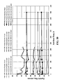
- FIG. 7 is a cumulative particle size distribution or PSD plot of ICs RSC-BD-18, RSC-BD-31, and RSC-BD 30 comprising 2.2 wt %, 1.0 wt %, and 1.6 wt % silica respectively.
- FIG. 8 is a PSD plot for the ICs and precipitated unsupported catalysts of FIG. 9 .
- FIG. 9 is a cumulative PSD plot for samples taken during attrition tests of ICs RSC-BD-31, RSC-BD-32 and RSC-BD-33 comprising 1.0 wt %, 2.0 wt %, and 1.5 wt % silica respectively.
- FIG. 10 is a plot of catalyst particle size as a function of attrition time for precipitated unsupported oxide catalyst as well as for magnesium aluminate catalyst IC RSC-BD-48.
- Raw catalyst refers to a formed, dry catalyst after calcination.
- the Fischer-Tropsch synthesis can be described as a polymerization reaction in which methyl species act as initiators for chain growth.
- Anderson-Schultz-Flory (ASF) product distribution shows that a polymerization-like process effectively describes the product distribution of the Fischer-Tropsch synthesis.
- Each carbon number surface species has a probability of continuing the chain growth or terminating the polymerization to produce product.
- the product spectrum may be characterized by the parameter, alpha, which is the chain growth probability.
- a hydrogen and carbon monoxide-containing gas stream is introduced into a Fischer-Tropsch reactor which preferably employs a catalyst slurry using an iron-based catalyst and more preferably a precipitated iron catalyst and most preferably a precipitated iron catalyst that is promoted with predetermined amounts of potassium and copper depending on the preselected probability of linear condensation polymerization and the molecular weight distribution sought.
- a structural promoter to a precipitated iron catalyst at a small percentage level significantly reduces the breakdown of the catalyst in a SBCR (slurry bubble column reactor).
- the amount of structural promoter is less than that used in the published art and does not substantially affect the activity and selectivity when compared with the structurally un-promoted catalyst, but enhances structural integrity during activation and operation.
- the mass ratio of SiO 2 :Fe is less than about 1:100 when the structural promoter comprises silica and less than about 8:100 when the structural promoter comprises silica sol, as will be described in more detail hereinbelow.
- an iron catalyst precursor prepared by co-precipitation of copper, silicon, magnesium, and aluminum with iron provides an FT catalyst that exhibits high activity, selectivity, and stability.
- the improved catalyst of the present disclosure comprises at least one structural promoter.
- the at least one structural promoter is selected from oxides of metals and metalloids and combinations thereof.
- the structural promoter may be referred to as a binder, a support material, or a structural support.
- the structural promoter is incorporated into the improved catalyst (IC) by coprecipitation.
- the structural promoter is added to a conventional precipitated catalyst subsequent precipitation of the conventional precipitate comprising iron hydroxides or iron carbonates.
- structural promoter is coprecipitated with the catalyst material, and additional structural promoter (e.g. binder) is added following the precipitation of the catalyst material.
- structural promoter comprising silica or silicate is added to a precipitate of a conventional precipitated unsupported catalyst, the precipitate comprising iron phases.
- the iron phases may be selected from iron hydroxides, iron carbonates, iron oxides, and combinations thereof.
- the precipitated unsupported catalyst that may be improved via embodiments of the present invention may comprise any suitable iron FT catalyst known to those of skill in the art.
- iron based catalysts described in U.S. Pat. No. 5,504,118 and U.S. Provisional Patent No. 60/955,142 are utilized due to their low cost.
- structural promoter comprises potassium silicate aqueous solution, which will be referred to herein as liquid potassium silicate.
- the precipitated unsupported catalyst that may be improved via embodiments of the present invention may comprise any suitable iron F-T catalyst known to those of skill in the art.
- the structural promoter is a liquid.
- the structural promoter comprises potassium silicate aqueous solution.
- the liquid structural promoter comprises tetraethyl ortho silicate, TEOS, or potassium silicate and is added such that the catalyst has a silica content of from about 1 wt. % to about 2.2 wt. %.
- liquid promoter is added to a precipitated unstrengthened catalyst (baseline catalyst) via incipient impregnation as known to those of skill in the art. Suitable incipient impregnation technique is described hereinbelow.
- Incipient wetness impregnation is a commonly used technique for the synthesis of heterogeneous catalysts.
- Active metal/metalloid precursor is typically dissolved in an aqueous or organic solution.
- the metal/metalloid-containing solution is then added to a catalyst containing the same pore volume as the volume of solution that was added. Capillary action draws the solution into the pores.
- the catalyst can then be dried and calcined to drive off the volatile components within the solution, depositing the metal/metalloid on the catalyst surface.
- Examples 1A to 1G hereinbelow describe ICs prepared according to embodiments of this disclosure, by the addition of structural promoter comprising liquid potassium silicate.
- the ICs of Examples 1A to 1G are formed via incipient wetness impregnation with liquid potassium silicate.
- the raw promoted precipitated unsupported catalyst to which liquid promoter is added via the present disclosure is useful in a slurry Fischer-Tropsch reactor.
- Suitable promoted precipitated unstrengthened iron catalyst is described in U.S. Pat. No. 5,504,118 and U.S. Provisional Patent No. 60/955,142.
- Preparation of precipitated unstrengthened catalyst may comprise: dissolving (E.G. at less than 150° F.) predetermined quantities of iron (and optionally copper and/or other metal(s)) in nitric acid to form a solution of ferrous nitrate, ferric nitrate (and cupric nitrate and/or other nitrates); sparging the solution with oxygen-containing gas during the step of dissolving; precipitating a catalyst precursor comprising metal oxides by the addition of sufficient base (e.g.
- the metal oxide comprises iron oxide selected from the group consisting of hydrous iron oxides and precipitated iron oxide, and may comprise oxides of copper, and other metal oxides. If copper is not precipitated with iron, the copper may be added following precipitation, as copper nitrate solution, as described in Example 21 hereinbelow.
- a spray dryer may be used to remove most of the water from the precipitated unsupported catalyst and at the same time to produce roughly spherical precipitated unsupported catalyst particles having diameters in the range of 40 to 100 microns, prior to the addition of structural promoter comprising silicate via incipient wetness technique.
- the unstrengthened catalyst may be heated in air (for example, to about 600° F.) to remove residual moisture and to stabilize the precipitated unsupported catalyst. In embodiments, this step is carried out in a fluidized bed which is heated electrically. In embodiments, silicate structural binder is then added to the calcined precipitated unsupported catalyst.
- a precipitated iron catalyst is employed and depending on the level of structural promoter comprising silicate and the preselected alpha, i.e. the polymerization probability desired, the weight ratio of K:Fe is from about 0.5:100 to about 6.5:100. More preferably, the weight ratio of K:Fe is from about 0.5:100 to about 2:100. In some embodiments, the weight ratio of K:Fe is about 1:100.
- the weight ratio of copper to iron is preferably between about 0.005 and 0.050, more preferably between about 0.0075 and 0.0125, and most preferably about 0.010. Copper may serve as a reduction promoter. In preferred embodiments, the weight ratio of Cu:Fe is about 1:100.
- structural promoter comprising silicate is added to a precipitated unsupported catalyst and the resulting improved catalyst (or “IC”) is then dried. Drying may be via spray drying as known to those of skill in the art. The dried IC may further be calcined to increase attrition resistance.
- IC improved catalyst
- a precipitated unsupported catalyst according to U.S. Pat. No. 5,504,118 and U.S. Provisional Patent No. 60/955,142 may be enhanced via the disclosed method via the addition of silicate binder.
- the herein disclosed method is useful for improving iron FT catalysts other than and including the precipitated unsupported catalyst described according to U.S. Pat. No. 5,504,118 and U.S. Provisional Patent No. 60/955,142 and described herein.
- the disclosed method may be used to enhance a precipitated unsupported catalyst containing structural promoter other than that presently disclosed. (That is, the use of the term ‘precipitated unsupported catalyst’ is not meant to limit the prior art catalysts which may be enhanced by the disclosed method to conventional catalysts comprising no structural promoter.)
- drying of the promoted IC may be achieved by any means known to one of skill in the art.
- drying may be achieved by spray drying, microwave energy, pan drying in an oven, or any other appropriate means.
- the drying exposes the IC to a maximum temperature in the range of from about 100° C. to about 200° C.
- the IC may be calcined. In embodiments, calcination is carried out at a temperature in the range of from about 250° C. to about 450° C. In some embodiments, calcination is carried out at a temperature in the range of from about 300° C. to about 400° C. In some embodiments, calcination is performed at a temperature of about 350° C.
- the particle size distribution (PSD) of the IC formed via addition of binder to a raw prepared precipitated unsupported catalyst is substantially the same as the PSD of the raw precipitated unsupported catalyst.
- a precipitated iron catalyst is improved by adding a structural promoter to the catalyst slurry.
- the silicon-containing binder comprises potassium silicate, colloidal silica, TEOS, or a combination thereof. Without wishing to be limited by theory, adding the binder to the slurry may improve dispersion of the metals in the catalyst and/or minimize damage to particles by the addition of silica via incipient wetness method at a later stage.
- the IC is formed by: dissolving (e.g. at less than 150° F.) predetermined quantities of iron and optionally copper in nitric acid to form a solution of ferrous nitrate, ferric nitrate and, in embodiments, cupric nitrate; sparging the solution with oxygen-containing gas during the step of dissolving; precipitating a catalyst precursor by the addition of sufficient base (e.g., ammonium hydroxide or sodium carbonate) to the solution formed; removing the ammonium nitrate and sodium nitrate formed during the precipitation step; washing the catalyst precursor; admixing a water slurry containing potassium carbonate to the catalyst precursor in an amount sufficient to promote the catalyst with potassium, and adding a structural promoter to the catalyst precursor to yield a promoted mixture. If copper is not precipitated with iron, the copper may be added following precipitation, as copper nitrate solution, as described in Example 2I hereinbelow. The promoted mixture may then be dried as described above.
- sufficient base e.g.
- the precipitating agent (base) is selected from NH 4 OH, (NH 4 ) 2 CO 3 , NH 4 HCO 3 , NaOH, Na 2 CO 3 , NaHCO 3 , KOH, K 2 CO 3 , KHCO 3 , and combinations thereof.
- the potassium carbonate and structural promoter are added simultaneously.
- the structural promoter comprises silica in colloidal form.
- the silica is silica sol.
- the at least one structural promoter comprises silica and the liquid structural promoter is added to the catalyst precursor (precipitated catalyst material) following the addition of potassium carbonate promoter.
- the catalyst precursor precipitated catalyst material
- potassium carbonate promoter examples 2A-21 hereinbelow describe ICs formed by the addition of liquid structural promoter comprising silica sol to a precipitated catalyst precursor.
- the silica sol comprises TMA LUDOX, LUDOX, LUDOX AS-30 or polysilicic acid (available from Sigma Aldrich, St. Louis, Mo.).
- Examples 2A, 2B and 2C hereinbelow describe improved catalysts according to this invention wherein the structural promoter comprises LUDOX.
- Examples, 2D and 2E describe the formation of inventive catalysts wherein the structural promoter comprises TMA LUDOX (TMA is tetramethyl ammonium).
- TMA is tetramethyl ammonium
- Examples 2F and 2H hereinbelow describe preparation of inventive catalysts wherein the structural promoter comprises polysilicic acid.
- Examples 2G and 2I hereinbelow describe inventive catalyst wherein the structural promoter comprises LUDOX AS-30.
- Examples 2J and 2K describe short and long term testing, respectively, of the liquid hydrocarbon production of the improved iron catalysts formed with silica sol structural promoter.
- the weight ratio of iron to potassium is in the range of from about 100:1 to about 100:5. In some embodiments, the weight ratio of iron to potassium is in the range of from about 100:2 to about 100:6. In more preferred embodiments, the weight ratio of iron to potassium is in the range of from about 100:3 to about 100:5. In some embodiments, the weight ratio of iron to potassium is in the range of from about 100:4 to about 100:5. In some preferred embodiments, the weight ratio of iron to potassium is in the range of from about 100:2 to about 100:4. In some specific embodiments, the weight ratio of iron to potassium about 100:3. In other certain embodiments, the weight ratio of iron to potassium about 100:5.
- the weight ratio of iron to copper is in the range of from about 100:1 to about 100:7. In some embodiments, the weight ratio of iron to copper is in the range of from about 100:1 to about 100:5. More preferably, the weight ratio of iron to copper is in the range of from about 100:2 to about 100:6. Still more preferably, the weight ratio of iron to copper is in the range of from about 100:3 to about 100:5. In some preferred embodiments, the weight ratio of iron to copper in the range of from about 100:2 to about 100:4. In other specific embodiments, the weight ratio of iron to copper about 100:5. In yet other specific embodiments, the weight ratio of iron to copper about 100:3.
- the iron to SiO 2 weight ratio may be in the range of from about 100:1 to about 100:8; alternatively, in the range of from 100:1 to 100:7. More preferably, in some embodiments, wherein the structural promoter is silica, the iron to SiO 2 weight ratio may be in the range of from about 100:2 to about 100:6. Still more preferably, the weight ratio of iron to silica is in the range of from about 100:3 to about 100:5. In some preferred embodiments, wherein the structural promoter is silica, the iron to SiO 2 weight ratio is about 100:5. In embodiments, wherein the structural promoter is silica, the iron to SiO 2 weight ratio may be in the range of from about 100:3 to about 100:7; alternatively, in the range of from about 100:4 to about 100:6.
- the Fe:Cu:K:SiO 2 mass ratio is about 100:4:3:5.
- an IC is formed by co-precipitation of at least one structural promoter with the iron of the iron catalyst.
- the IC comprises more than about 50 wt % of oxides including iron oxides and other oxides.
- the metal of the mixed oxides is selected from silicon, magnesium, aluminum, copper, iron, and combinations thereof.
- the IC comprises up to 50 wt % oxides selected from oxides of copper, magnesium, silicon, aluminum and combinations thereof.
- the IC is formed by coprecipitation with magnesium.
- magnesium is coprecipitated from magnesium nitrate.
- the IC is formed by coprecipitation with copper.
- the IC is formed by coprecipitation with aluminum.
- the IC is formed by coprecipitation from aluminum nitrate.
- the IC is formed by coprecipitation of iron with magnesium, silica, aluminum, copper, or a combination thereof.
- Example 3 hereinbelow describes ICs comprising oxides of magnesium, copper, and aluminum in addition to iron oxides, and formed by coprecipitation of iron with magnesium, copper, and aluminum from nitrate solutions thereof.
- the structural promoter comprises tetraethyl orthosilicate, TEOS.
- TEOS tetraethyl orthosilicate
- Example 4 hereinbelow describes an IC comprising SiO 2 and formed by coprecipitation of the catalyst from a solution comprising TEOS structural promoter.
- iron catalyst is improved by adding a support material during catalyst formation.
- a magnesium-containing compound serves as support material.
- the magnesium-containing compound comprises magnesium aluminate (spinel) MgAl 2 O 4 .
- the catalyst comprises at least one other support material selected from SiO 2 , TiO 2 , Al 2 O 3 , and combinations thereof. Magnesium may also serve as a promoter.
- the IC comprises SiO 2 and/or Al 2 O 3 in addition to magnesium oxide (magnesia). SiO 2 and/or Al 2 O 3 may add to the attrition resistance of an IC comprising magnesium.
- the support material provides structural support, increased surface area, chain growth promotion or a combination thereof.
- IC is formed by coprecipitation of iron, copper, magnesium and aluminum.
- the ratio of magnesium to aluminum atoms in the IC and/or in the pre-precipitation mixture is in the range of from about 0.4 to about 0.6. In embodiments, the ratio of magnesium to aluminum is about 0.5.
- co-precipitation is performed by dissolution of the metals in nitric acid as described in U.S. Pat. No. 5,504,118 and hereinbelow.
- the precipitate may be washed as known to one of skill in the art.
- the precipitate is washed with high quality water which is essentially free of chlorine.
- the washed precipitate may be alkalized by, for example, the addition of potassium carbonate.
- alkalization is performed prior to spray drying in order to adjust the Fe:K ratio to the desired value.
- alkalization is performed prior to spray drying in order to provide the desired Fe:K ratio.
- the precipitated IC may subsequently be dried as discussed hereinabove.
- Production of the IC may further comprise calcining the dried IC.
- Calcination may be carried out at a temperature in the range of from about 250° C. to about 450° C. In some embodiments, calcination is performed at a temperature in the range of from about 350° C. to about 400° C. In specific embodiments, calcination occurs at a temperature of about 350° C.
- a prepared IC formed via co-precipitation from mixed metal nitrates as described herein may be further enhanced by incorporating silica as described in Section II hereinabove.
- structural promoter potassium silicate or TEOS; about 1 wt % to 3 wt %) may be added as described in Section IIA hereinabove to precipitate comprising mixed oxides.
- precipitation of the mixed metal oxides of the IC may occur in the presence of TEOS.
- Example 5 hereinbelow describes IC comprising oxides of silica, magnesium, aluminum, and copper, as well as iron oxides.
- the IC of Example 5, RSC-BD-48 is formed by coprecipitation of iron, copper, magnesium, and aluminum in the presence of TEOS.
- Example 10 hereinbelow describes the enhanced attrition resistance of RSC-BD-48.
- the IC is activated prior to use in an FT process. In certain embodiments, the IC is activated in situ.
- Many different activating procedures for promoted iron Fischer-Tropsch catalysts have been described in the literature. High activity of the catalyst has previously been correlated with the presence of iron carbides after the activation procedure. Effective procedures include the use of carbon monoxide at 325° C. at 0.1 atm pressure. The presence of copper and potassium in the catalyst may affect activation of the catalyst.
- the IC is activated by any means known to one of skill in the art.
- the IC is pre-treated in hydrogen.
- the IC is pretreated with a gas comprising carbon monoxide.
- the IC is pre-treated in synthesis gas.
- pre-treatment occurs at preselected conditions of temperature and pressure. In embodiments, these pre-selected conditions of temperature encompass a temperature of from about 250° C. to about 300° C. In embodiments, these pre-selected conditions of pressure encompass a pressure of from about 5 atm. to about 10 atm.
- the activity and selectivity of the IC is improved by subjecting the IC to a hydrogen-rich synthesis gas at elevated temperature and pressure.
- the reaction of carbiding of the iron catalyst precursor using a hydrogen-rich synthesis gas and the subsequent Fischer-Tropsch reaction both produce water. Without wishing to be limited by theory, it is believed that the presence of this water prevents over-carburization of the catalyst and thereby improves the activity and selectivity of the catalyst.
- hydrogen-rich synthesis gas is used in lieu of an inert gas for maintaining the IC in suspension while the slurry is being heated to approximately 200° C.
- the synthesis gas is replaced by an inert gas (nitrogen or carbon dioxide) until the activation temperature has been attained at which time activation is carried out using synthesis gas.
- the initial load of IC in a commercial-scale slurry reactor comprising several thousand pounds of catalyst is pretreated in the full-scale slurry reactor.
- a separate pretreatment reactor may be desirable.
- the pretreatment reactor may be similar in design to the large Fischer-Tropsch reactor, but much smaller.
- the batch of slurry containing the pretreated catalyst is pumped into the large reactor as known to those of skill in the art.
- small amounts of IC i.e. up to 10% by weight of the total amount of catalyst in the F-T reactor, are activated in situ by adding raw catalyst directly to the reactor at operating conditions.
- the IC is activated by contacting the catalyst with a mixture of gaseous hydrogen and carbon monoxide at a temperature of from about 250° C. to 300° C., for about 0.5 to 5 hours, with a water vapor partial pressure of about 1 psia, and a hydrogen to carbon monoxide mol (or volume) ratio of about 1.3 to 1.5, the activation being effective to increase the selectivity of the activated IC in the subsequent formation of liquid hydrocarbons in a Fischer-Tropsch reaction.
- the syngas for activation has a H 2 :CO mol ratio of about 1.4.
- activation in syngas occurs for a time period up to 6 hours.
- the catalyst in wax or oil is first heated to 275° C. in H 2 and then syngas is fed for activation.
- the improved catalyst of this disclosure may be activated using a “typhoon” activation method.
- in situ catalyst activation is performed by heating the catalyst to 275° C. in nitrogen, feeding syngas at a H 2 :CO ratio of 1.4 once attaining a temperature of 275° C., activating at 275° C. under 140 psig pressure for 4-24 hours (depending on the space velocity).
- IC comprising support material (e.g. MgAl 2 O 4 , MgAl 2 O 4 —SiO 2 , Al 2 O 3 , SiO 2 , SiO 2 —Al 2 O 3 , etc.) in oil or wax is first heated to 200° C. in N 2 , and then syngas is fed, and the temperature is ramped to a temperature in the range of about 285° C. to 300° C.
- the syngas used for activation has a H 2 :CO ratio of about 0.7.
- the temperature is ramped from 200° C. to a temperature of from about 285° C. to about 300° C. at a ramp rate in the range of from 1° C./min to about 5° C./min.
- IC catalysts are activated with 100% CO.
- the methods of producing iron-based catalysts yield catalysts for which the structural integrity of the catalyst is enhanced while maintaining substantial catalytic activity. It has been found (see Examples hereinbelow), that at concentrations of structural promoter less than conventionally utilized, substantial catalyst activity is maintained.
- Example 2K hereinbelow describes long term testing of inventive catalyst and the rate of overall activity decline (ROAD) (i.e., the deactivation rate) of the catalysts.
- the FT activity of the improved catalyst is at least 10% greater than the activity of previously reported attrition resistant catalysts.
- the selectivity of the IC (as compared to baseline precipitated unsupported catalyst) is not substantially changed by the improvement.
- the CO 2 and CH 4 selectivities of the IC are not negatively altered when compared to the unstrengthened precipitated unsupported catalyst, as shown for catalysts formed with silica sol structural promoter in Examples 2J and 2K hereinbelow.
- the methane selectivity of the improved catalyst of this disclosure is less than about 4%. In some embodiments, the methane selectivity of the improved catalyst of this disclosure is less than about 3%. In some embodiments, the methane selectivity of the improved catalyst of this disclosure is less than about 2%. In some preferred embodiments, the methane selectivity of the improved catalyst of this disclosure is less than about 1%.
- the liquid yield from IC is not substantially reduced from the liquid yield obtained with baseline precipitated unsupported catalyst.
- the CO conversion is maintained or increased by the use of liquid structural promoter as disclosed herein.
- the IC of the present disclosure produces a high alpha catalyst having chain-growth characteristics substantially similar to the chain growth characteristics of the precipitated unsupported catalyst. Examples 2J and 2K describe short and long term testing of inventive catalysts, including CO conversion, alpha, and the amount of fines produced therefrom.
- catalyst is separated from reaction product via a separation unit from which a wax filtrate is obtained.
- One method to maintain the slurry level to a constant value is to use a cross-flow filter to remove filtered wax while returning the catalyst to the reactor.
- Spray-dried precipitated iron oxide particles typically comprise clusters of many nanometer size particles which can break from the cluster due to stresses of chemical transformations during activation or due to mechanical stresses encountered in the slurry bubble column reactor. These particles can be deleterious to the action of the separation unit, and mandate the use of multiple separation units for removal of catalyst from the reaction product.
- Activated FT catalyst typically comprises a core comprising Fe 3 O 4 and an active iron carbide (Fe x C, e.g. Fe 2.2 C and/or Fe 2.5 C) outer shell around the Fe 3 O 4 core. Carbon may be formed during the synthesis, separate from the cluster, and hinder the performance of the separation unit(s).
- the separation unit comprises a metal filter, a cross-flow filter (e.g. a Mott filter), a dynamic settler, or a combination thereof.
- the separation unit may comprise a “dynamic settler” as disclosed in U.S. Pat. Nos. 6,068,760; 6,730,221; and 6,712,982 to Rentech.
- the content of catalyst in the wax filtrate is significantly less when using IC than the content of catalyst in the wax filtrate typically obtained when using conventional precipitated unsupported catalyst ( ⁇ 1000 ppm).
- further filtration is required to reduce the catalyst content of the wax filtrate to the range required for subsequent processes, e.g.
- the catalyst of the present disclosure may eliminate the need for further filtration by virtue of the improved structural integrity/ease of separation of the IC from the reaction product (e.g. wax product).
- the improved catalyst of this disclosure produces a smaller quantity of fines than precipitated unsupported catalysts during catalyst activation and/or FT reaction.
- a chemical attrition index based on 10 micrometer sized particles, CAI-10 was defined as the difference in the percentage of particles having a size greater than 10 ⁇ m before and after activation divided by the percentage of particles having a size greater than 10 ⁇ m after activation.
- a chemical attrition index based on 20 micrometer sized particles, CAI-20 was defined as the difference in the percentage of particles having a size greater than 20 ⁇ m before and after activation divided by the percentage of particles having a size greater than 20 ⁇ m after activation.
- the CAI-10 of the IC is reduced by a factor of greater than about 10 relative to the CAI-10 of an unsupported catalyst. In embodiments, the CAI-10 is reduced by a factor of greater than about 15. In embodiments, the CAI-10 is reduced by a factor of greater than about 20. In embodiments, the CAI-20 of an IC according to this disclosure is reduced by a factor of greater than about 7 relative to unsupported iron catalyst. In embodiments, the CAI-20 is reduced by a factor of greater than about 10. In embodiments, the CAI-20 is reduced by a factor of greater than about 20. In embodiments, the CAI-20 is reduced by a factor of greater than about 30.
- Examples 2J and 2K describe short and long term testing of inventive catalysts, and the amount of fines produced therefrom.
- Example 6 hereinbelow describes a settling test of a silica-containing IC of the present disclosure.
- Example 9 hereinbelow describes the separation of ICs from hydrocarbon product mixtures.
- Example 7 hereinbelow describes autoclave and SBCR test results of IC catalyst formed with potassium silicate structural promoter.
- Example 8 hereinbelow describes the results of attrition tests and the resulting particle size distributions for several of the silica-containing ICs formed with potassium silicate structural promoter.
- a raw unsupported precipitated iron catalyst promoted with copper and potassium was prepared according to the description in U.S. Pat. No. 5,504,118 and U.S. Provisional Patent No. 60/955,142.
- the raw catalyst was made using elemental iron and copper as starting materials.
- the first step in the preparation of the raw catalyst was dissolution of the metals in nitric acid to form a mixture of ferrous nitrate, ferric nitrate and cupric nitrate in appropriate proportions.
- the ratio of water to acid in an important parameter and may be adjusted to give a weight ratio of about 6:1.
- the dissolution of the metals in nitric acid is accompanied by evolution of nitrogen oxides, principally nitric oxide and nitrogen dioxide.
- Nitric oxide has limited solubility in the acid, but it can be readily oxidized to nitrogen dioxide by contact with air or oxygen. Nitrogen dioxide dissolves in water producing nitric acid and nitric oxide.
- oxygen may be bubbled through the solution while the metals are being dissolved.
- the small amount of nitrogen dioxide which escapes from the vessel is scrubbed using a potassium hydroxide solution.
- the mixture was stirred until all of the metals dissolved.
- the temperature of the solution increased as the metals dissolved, but was controlled to a maximum temperature of about 70° C.
- the next step in the process was precipitation of a catalyst precursor from the nitrate solution using ammonium hydroxide.
- Ammonium hydroxide was prepared by dissolving anhydrous ammonia in water. Ammonium hydroxide at ambient temperature was added to the hot nitrate solution until the pH of the solution reached about 7.4. At this point, all of the metals had precipitated out as oxides. The mixture was cooled to about 80° F. and the final pH was adjusted to about 7.2.
- the catalyst precursor was washed free of ammonium nitrate using high quality water which is preferably free of chlorine.
- the slurry may be pumped from the precipitation vessel into a holding tank located upstream of a vacuum drum filter.
- the catalyst precursor may be allowed to settle in the holding tank and a clear layer of concentrated ammonium nitrate solution may form above the solids. This layer may be drawn off before the slurry is washed and filtered.
- a vacuum drum filter fitted with water spray bars may be used for washing the catalyst precursor and concentrating the slurry. The electrical conductivity of the filtrate may be monitored to ensure complete removal of ammonium nitrate from the slurry.
- potassium carbonate was added in an amount appropriate for the quantity of iron contained in the batch.
- Potassium is a promoter for chain growth and may also maintain the catalyst in iron carbide form. Adding more than appropriate amount of potassium may cause formation of more oxygenated products which may oxidize the catalyst.
- Potassium carbonate was added to the slurry after washing was completed and prior to spray drying. The potassium carbonate was dissolved in a small amount of water and this solution was mixed thoroughly into the slurry to distribute the potassium uniformly.
- the weight percent of solid catalyst material in the slurry at this point is a value of between about 8 to about 12.
- Examples 1A to 1G contain detailed descriptions of the manufacturing process for inventive catalysts with different structural promoters.
- ICs were prepared comprising SiO 2 concentrations of 1.0 wt %, 1.5 wt %, 1.6 wt %, 2.0 wt %, 2.2 wt %, and 10 wt %, corresponding to IC catalysts RSC-BD-31, RSC-BD-33, RSC-BD-30, RSC-BD-32, RSC-BD-18, and RSC-BD-22 respectively.
- step (2) 50.0 g of precipitated iron catalyst prepared using the method of U.S. Pat. No. 5,504,118 and U.S. Provisional Patent No. 60/955,142, was impregnated by mixing thoroughly with 12.7 g of aqueous solution of potassium silicate prepared in step 1.
- step (3) the material obtained in step 2 was first heated to 125° C. at the rate of 2° C./min, and held at this temperature for 12 h, and then ramped to 350° C. at the rate of 11/min, and calcined at this temperature for 16 h. (It is noted that this catalyst could also have been prepared by adding potassium silicate to precipitate prior to spray drying.) In step 2, the catalyst was spray dried and calcined prior to the addition of solution from (1).
- step (2) 50.0 g of precipitated iron catalyst prepared as described in U.S. Pat. No. 5,504,118 and U.S. Provisional Patent No. 60/955,142 was impregnated by mixing thoroughly with 12.7 g of aqueous solution of potassium silicate prepared in step 1.
- step (3) the material obtained in step 2 was first heated to 125° C. at the rate of 2° C./min, and held at this temperature for 12 h, and then ramped to 350° C. at the rate of 1°/min, and calcined at this temperature for 16 h. (It is noted that this catalyst could also have been prepared by adding potassium silicate to the precipitate prior to spray drying.)
- step (2) 50.0 g of precipitated iron catalyst prepared as described in U.S. Pat. No. 5,504,118 and U.S. Provisional Patent No. 60/955,142 was impregnated by mixing thoroughly with 39.0 g of aqueous solution of potassium silicate prepared in step 1. Incipient wetness impregnation was repeated three times using 13 g of aqueous solution of potassium silicate, and the material was dried in an oven for about 4 h each time after each impregnation.
- step (3) the material obtained in step 2 was first heated to 125° C. at the rate of 2° C./min, and held at this temperature for 12 h, and then ramped to 350° C. at the rate of 11/min, and calcined at this temperature for 16 h. (It is noted that this catalyst could also have been prepared by adding potassium silicate to the precipitate prior to spray drying.)
- step (2) 50.0 g of precipitated iron catalyst prepared as described in U.S. Pat. No. 5,504,118 and U.S. Provisional Patent No. 60/955,142 was impregnated by mixing thoroughly with 11.9 g of aqueous solution of potassium silicate prepared in step 1.
- step (3) the material obtained in step 2 was first heated to 125° C. at the rate of 2° C./min, and held at this temperature for 6 h, and then ramped to 350° C. at the rate of 2°/min, and calcined at this temperature for 16 h. (It is noted that this catalyst could also have been prepared by adding potassium silicate to the precipitate prior to spray drying.)
- step (2) 50.0 g of precipitated iron catalyst prepared as described in U.S. Pat. No. 5,504,118 and U.S. Provisional Patent No. 60/955,142 was impregnated by mixing thoroughly with 12.6 g of aqueous solution of potassium silicate prepared in step 1.
- step (3) the material obtained in step 2 was first heated to 125° C. at the rate of 2° C./min, and held at this temperature for 12 h, and then ramped to 350° C. at the rate of 2°/min, and calcined at this temperature for 16 h. (It is noted that this catalyst could also have been prepared by adding potassium silicate to the precipitate prior to spray drying.)
- step (2) 130.0 g of precipitated iron catalyst prepared as described in U.S. Pat. No. 5,504,118 and U.S. Provisional Patent No. 60/955,142 was impregnated by mixing thoroughly with 32.5 g of aqueous solution of potassium silicate prepared in step 1.
- step (3) the material obtained in step 2 was first heated to 125° C. at the rate of 2° C./min, and held at this temperature for 12 h, and then the temperature was ramped to 350° C. at the rate of 2°/min, and the material calcined at this temperature for 16 h.
- this catalyst could also have been prepared by adding potassium silicate to the precipitate prior to spray drying.
- step (2) 130.0 g of precipitated iron catalyst prepared as described in U.S. Pat. No. 5,504,118 and U.S. Provisional Patent No. 60/955,142 was impregnated by mixing thoroughly with 32.5 g of aqueous solution of potassium silicate prepared in step 1.
- step (3) the material obtained in step 2 was first heated to 125° C. at the rate of 2° C./min, and held at this temperature for 12 h, and then the temperature was ramped to 350° C. at the rate of 2°/min, and the material calcined at this temperature for 16 h. (It is noted that this catalyst could also have been prepared by adding potassium silicate to the precipitate prior to spray drying.)
- AR52-01 100Fe/4Cu/3K/5SiO 2 ; Silica Source: 30% LUDOX
- the mixture was stirred using an IKA-WERKE mechanical stirrer equipped with a 3-inch-4-propeller blade stirring at a rate of 220 rpm at room temperature for 2 hours.
- the Cu did not dissolve.
- the mixture was then heated to 70° C. and maintained at this temperature for 40 minutes, during which time the Cu appeared to dissolve, at about 65° C. The temperature may have slightly overshot due to a non-optimal placement of the thermocouple.
- a quantity of 250 mL ammonium hydroxide (29%) was diluted with 250 mL deionized water.
- a Eutech Instruments Oakton pH meter equipped with a semi-solids electrode was calibrated using Orion Application Solutions buffers at pH 4.00 and 7.00, and inserted into the reaction mixture, and the pH was monitored.
- the pH was initially 0.20.
- the ammonium hydroxide solution was added drop-wise over a period of 78 minutes and the pH changed to 7.16.
- the mechanical stirring was increased around pH 3.0 to a rate of 400 rpm due to a large amount of precipitation.
- the addition of ammonium hydroxide was stopped and the stirring was continued for an additional 25 minutes.
- AR52-02 and AR-52-09 (100Fe/4Cu/3K/5SiO 2 ; Silica Source: 30% LUDOX)
- Example 2A A larger batch than that of Example 2A was prepared by combining, prior to spray drying, two batches each similar to AR52-01 described in Example 2A hereinabove.
- the first batch of the two batches differed from AR52-01 in that (1) the nitric acid was added over 82 minutes, (2) the mixture was stirred at room temperature for 25 minutes after the nitric acid addition was complete, rather than for 2 hours, (3) after heating and cooling the reaction mixture the initial pH was 0.54, (4) the ammonium hydroxide solution was added drop-wise over 92 minutes, and (5) the pH changed to 7.15.
- This mixture was filtered using a Sigma Aldrich polypropylene filter paper (originally 102 cm wide cut to 24 cm diameter, Batch # 3110).
- the remaining moist solid from this batch was collected in a 2 L beaker and stored covered for 2 days.
- the second batch made the following day, differed from AR52-01 in that: (1) the nitric acid solution was added over 74 minutes; (2) the pH before and after ammonium hydroxide addition was 1.01 and 7.15, respectively; and (3) the ammonium hydroxide solution was added over a period of 102 minutes.
- the second batch was filtered using the filter paper described above for the first batch.
- the two batches were combined the following day into one 4 L beaker, 280 mL of water was added, and the mixture was stirred until uniform.
- a quantity of 8.448 g K 2 CO 3 dissolved in 200 mL water was then added and stirring continued for 15 minutes.
- An amount of 26.9 g LUDOX 30 silica (as above) in 60 mL water was added and stirring continued for 25 minutes.
- the mixture was spray dried to microspheric particles in the size range of 40-100 micrometers, with a mean size of about 80 micrometer, using a Type H Mobil Niro Spray Dryer consisting of a two-fluid nozzle atomizer, drying chamber, air disperser, main chamber, product collection section, air ducts, cyclone, exhaust fan, air heater, and instrument panel.
- the feed slurry at 16 ⁇ 1% solids, was introduced to the spray dryer through a nozzle from the bottom with the drying air cross-flowing from the top.
- the spray drying conditions were: Inlet temperature, 370 ⁇ 2° C., outlet temperature, 96 ⁇ 1° C., water setup flow, 4.0 to 4.5 kg/hr (feed flow is set with water then switched to the actual slurry feed); atomizer air flow, 1 bar with a 30% setting on a variable area flow meter. Coarse and fine samples were collected.
- the coarse sample was calcined under the following conditions: AR52-02B1 (1 day later)—Heat at 30° C./min to 380° C., hold for 4 hours then cool to room temperature; AR52-02B2 (6 days later)—Heat at 1° C./min to 300° C., hold for 4 hours then cool to room temperature at a rate of 1° C./min; AR52-02B2-b (32 days later)—Heat at 1° C./min to 300° C., hold for 4 hours then cool to room temperature at a rate of 1° C./min.
- AR53-01 100Fe/5Cu/3K/5SiO 2 ; Silica Source: 30% LUDOX
- the reagents and procedure for this batch were similar to the ones described for AR52-01 in Example 2A with the following differences: (1) 4.00 g Cu° (Alpha Aesar, Lot # B23L30, 99.5%, ⁇ 150 mesh) were used; (2) the nitric acid solution was added drop-wise over 90 minutes; (3) after the addition of nitric acid was complete, the mixture was allowed to stir at room temperature for 25 minutes; (4) after heating and cooling the reaction mixture, ammonium hydroxide solution was added drop-wise over 90 minutes; and (5) the pH changed from 0.80 to 7.16. After filtration and rinsing, the solid was collected and stored in a 2 L beaker and left covered overnight.
- a quantity of 89.41 g of the 894.05 g of moist solid was separated out, and 140 mL deionized water was added to the remaining 804.64 g.
- a slurry was made using the same procedure as described for AR52-01. The mixture was spray dried as described in Example 2B hereinabove; coarse and fine samples were collected. Coarse sample was calcined the same day under the following conditions for the sample coded AR53-01B1: Heat at 30° C./min to 380° C., hold for 4 hours then cool to room temperature.
- the 412.13 g of moist solid was then divided into 2 equal mass portions. 100 mL deionized water was added to the first portion and stirred until uniform. A quantity of 1.056 g potassium carbonate in 140 mL deionized water was added slowly to the mixture. The mixture was stirred for 15 minutes, sonicated for 10 minutes. Next, 2.965 g silica solution (tetramethyl ammonium stabilized colloidal silica, 34 wt % suspension in water, Sigma-Aldrich, Lot # 12806HE) in 200 mL deionized water was added and this mixture was stirred for an additional 15 minutes. The pH of this slurry was reduced from 7.35 to 4.00 by the addition of concentrated nitric acid.
- silica solution tetramethyl ammonium stabilized colloidal silica, 34 wt % suspension in water, Sigma-Aldrich, Lot # 12806HE
- a quantity of 4.224 g potassium carbonate in 140 mL deionized water was then added slowly and stirring continued for an additional 15 minutes.
- An amount of 11.862 g of silica solution (tetramethyl ammonium stabilized colloidal silica, 34 wt % suspension in water, Sigma-Aldrich, Lot # 12806HE) was added with 30 mL deionized water and the mixture was stirred for another 25 minutes, then spray dried as described in Example 2B hereinabove.
- the coarse sample was calcined 1 day later under the following conditions: AR57-01B1—Heat at 30° C./min to 380° C., hold for 4 hours, then cool to room temperature.
- AR57-01B2 Heat at 1° C./min to 300° C., hold for 4 hours then cool to room temperature at a rate of 1° C./min.
- iron powder Hoeganaes, 98.61%, ⁇ 325 mesh
- copper powder Alfa Aesar, 99.5%, +100/ ⁇ 40 mesh
- 403.2 g (288 ml) of 70% nitric acid, HNO 3 , from Fisher Scientific (Certified ACS PLUS grade) was dissolved in 1,208 ml of deionized water. Under mechanical stirring, the nitric acid solution was added to the iron-copper slurry dropwise. The initial addition rate was 5-6 ml/min to keep the temperature of the mixture at or below 30° C.
- a solution of 4.224 g potassium carbonate (K 2 CO 3 , Alfa Aesar, ACS reagent grade) in 30 ml deionized water was added to the slurry and mixed well with it.
- the polysilicic acid solution was added to the slurry and mixed well with it for 10 minutes.
- the obtained mixture was spray dried to microspheric particles in the size range of 40-100 micrometers, as described in Example 2B hereinabove. After spray drying, 41.5 g of fines and 110.0 g of coarse sample were recovered.
- the coarse spray dried sample was calcined in a porcelain crucible soon after the spray drying to minimize aging. The material was calcined at 300° C. for 4 hours, at a heating and cooling rate of 1° C./min.
- AR69-01 100Fe/4Cu/3K/5SiO 2 ; Silica Source: LUDOX®AS-30)
- iron powder Hoeganaes, 98.61%, ⁇ 325 mesh
- copper powder Alfa Aesar, 99.5%, +100/ ⁇ 40 mesh
- 403.2 g (288 ml) of 70% nitric acid, HNO 3 , from Fisher Scientific (Certified ACS PLUS grade) was dissolved in 1,208 ml of deionized water. Under mechanical stirring, the nitric acid solution was added to the iron-copper slurry dropwise. The initial addition rate was 5-6 ml/min to keep the temperature of the mixture at or below 34° C.
- the rate of addition was then increased without increasing the temperature above 34° C., and the addition of the acid was complete after about 93 minutes.
- the mixture was stirred for an additional period of 30 minutes at 35° C., and then was heated to 70° C. at ⁇ 3° C./min and maintained at 70° C. for 40 minutes.
- a sodium carbonate solution was prepared by combining 246.14 g anhydrous Na 2 CO 3 with 800 ml deionized water and the solution was heated to 80° C.
- the initial temperature and pH of the base solution was recorded to be 83° C. and 10.79.
- the initial acid temperature was 67° C.
- the iron-copper nitrate (acid) solution was added to the base solution within 6 minutes, with vigorous stirring, and the resulting mixture with the metal oxide precipitate was filtered immediately over a Büchner funnel and washed six times with 2,000 ml of deionized water (total of 12,000 ml).
- the rinse water was at 85-90° C. While filtering, the catalyst was mixed manually periodically to afford effective washing and allow homogenous contact between the rinse water and the solid. After the fourth washing the filter funnel was covered and left untouched overnight before continuing the last two washings.
- the iron-copper oxide filter residue was dried to a sufficient dryness level to allow easy removal from the filter paper, and was transferred to a 2-liter beaker.
- AR70-01 100Fe/4Cu/3K/5SiO 2 ; Silica Source: Polysilicic Acid
- iron powder Hoeganaes, 98.61%, ⁇ 325 mesh
- copper powder Alfa Aesar, 99.5%, +100/ ⁇ 40 mesh
- 403.2 g (288 ml) of 70% nitric acid, HNO 3 , from Fisher Scientific (Certified ACS PLUS grade) was dissolved in 1,208 ml of deionized water. Under mechanical stirring, the nitric acid solution was added to the iron-copper slurry dropwise. The initial addition rate was 5-6 ml/min to keep the temperature of the mixture at or below 34° C.
- the rate of addition was then increased without increasing the temperature above 34° C., and the addition of the acid was complete after about 94 minutes.
- the mixture was stirred for an additional period of 25 minutes at 35° C., and then was heated to 70° C. at ⁇ 3° C./min and maintained at 70° C. for 40 minutes.
- a sodium carbonate solution was prepared by combining 246.14 g anhydrous Na 2 CO 3 with 800 ml deionized water and the solution was heated to 80° C.
- the initial temperature and pH of the base solution was recorded to be 88° C. and 10.23, respectively.
- the initial acid temperature was 80° C.
- the iron-copper nitrate (acid) solution was added to the base solution within 5 minutes, with vigorous stirring, and the resulting mixture with the metal oxide precipitate was filtered immediately over a Büchner funnel and washed six times with 2,000 ml of deionized water (total of 12,000 ml).
- the rinse water was at 85-90° C. While filtering, the catalyst was mixed manually periodically to afford effective washing and allow homogenous contact between the rinse water and the solid. After the third washing the filter funnel was covered and left untouched overnight before continuing the last three washings.
- the iron-copper oxide filter residue was dried to a sufficient dryness level to allow easy removal from the filter paper, and was transferred to a 2-liter beaker.
- Polysilicic acid was prepared as above (Example 2F).
- AR72-02 (100Fe/4Cu/3K/5SiO 2 ; Silica Source: LUDOX®AS-30)
- iron powder (Hoeganaes, 98.61%, -325 mesh) was slurried with 360 ml of deionized water. 362.9 g (259.2 ml) of 70% nitric acid, HNO 3 , from Fisher Scientific (Certified ACS PLUS grade), was dissolved in 1,087 ml of deionized water. Under mechanical stirring, the nitric acid solution was added to the iron slurry dropwise. The initial addition rate was 5 -6 ml/min to keep the temperature of the mixture at or below 32° C. The rate of addition was then increased without increasing the temperature above 32° C., and the addition of the acid was complete after about 70 minutes.
- the mixture was stirred for an additional period of 25 minutes at 35° C., and then was heated to 70° C. at ⁇ 3° C/min and maintained at 70° C. for 40 minutes. The solution was then cooled to 35° C. as quickly as possible.
- 8.074 g iron (as above) was slurried with 40 ml deionized water.
- An acid solution was prepared by dissolving 28.8ml nitric acid (as above) in 121 ml deionized water. The acid solution was added to the iron slurry slowly at a temperature not higher than 28° C. This solution was added to the other solution.
- the catalyst was mixed manually periodically to afford effective washing and allow homogenous contact between the rinse water and the solid.
- the iron oxide filter residue was dried to a sufficient dryness level to allow easy removal from the filter paper, and was transferred to a 2-liter beaker and stored covered overnight.
- catalyst composition is given in the second column from left as relative mass
- catalyst calcination conditions are presented in the third column from left as “rate of heating”-“calcination temperature”-“calcination time”.
- reaction hours in column four from left is time on stream (TOS).
- TOS time on stream
- the next columns to the left are: “CO”-percent CO conversion; “CO 2 ”—CO 2 selectivity, percent formed in gas; “CH 4 ”—methane selectivity as percent of product; “Paraffin alpha”—calculated Anderson-Schulz-Flory (ASF) chain growth probability of paraffins; “Olefin alpha”—ASF calculated for olefins.
- Experiment H44 was run after activation under H 2 :CO (ratio 0.77) at 210° C. for 6 hr. An observation of Table 1 reveals that using the Typhoon activation only a few tests showed a good combination of stability and activity.
- Experiment F31 shows the effect of less Cu in the catalyst: A drastic loss of activity; but high stability as judged by the “Rate of Overall Activity Decline” (ROAD, see above) of 0.010.
- ROAD Rating of Overall Activity Decline
- catalyst AR-52-09B1 was activated with syngas at a hydrogen to carbon monoxide ratio of 0.7.
- the temperature was ramped to 150° C. at a rate of 2° C./min, and from 150-270° C. at a rate of 0.5° C./min.
- Activation pressure was 30 psig, and the space velocity (SV) was 2.73 nl/h/g Fe. Activation conditions were maintained for 24 hours.
- reaction was carried out at 242° C.-248° C., a pressure of 375 psig (2.027 slph N 2 , 10.307 slph CO, 7.936 slph H 2 ), a space velocity of 3.57 nl/h/g Fe, and synthesis gas having a hydrogen to carbon monoxide ratio of 0.77.
- step (1) Fe(NO 3 ) 3 9H 2 O (257.3 g), Cu(NO 3 ) 2 3H 2 O (1.4 g), Mg(NO 3 ) 2 .6H 2 O (64.1 g) and Al(NO 3 ) 3 .9H 2 O (187.6 g) were dissolved in 2000 mL DI water.
- step (2) the slurry was precipitated at 70° C. with 2000 mL of aqueous solution of Na 2 CO 3 (207.8 g) under vigorous mixing. At the end of the precipitation, measured pH was 7.23 at 26.8° C.
- step (3) the precipitate was filtered and washed repeatedly with warm water until the pH was near neutral.
- Alternative methods can also be used to measure nitrates.
- step (4) after removal of excess water, 2.0 g of aqueous solution of K 2 CO 3 (0.63 g) was added to the gelled slurry, and mixed thoroughly.
- step (5) the slurry was slowly dried and ground in a mortar using a pestle.
- step (6) the ground powder material was placed in an oven and first heated to 125° C. at the rate of 2° C./min, and then held at this temperature for 16 h. The dry powder was then heated to 350° C. at the ramp rate of 11/min, and kept at this calcination temperature for 16 h.
- step (1) Fe(NO 3 ) 3 .9H 2 O (5145.9 g), Cu(NO 3 ) 2 .3H 2 O (27.1 g), Mg(NO 3 ) 2 .6H 2 O (256.4 g) and Al(NO 3 ) 3 9H 2 O (750.3 g) were dissolved in 2000 mL DI water.
- step (2) the slurry was then precipitated under vigorous mixing at 70° C. with 2000 mL of aqueous solution of Na 2 CO 3 (2460.9 g). At the end of the precipitation, measured pH was 7.2 at 25° C.
- step (3) the precipitate was filtered and washed repeatedly with warm water until the pH was about neutral.
- Alternative methods can also be used to measure nitrates.
- step (5) after removal of excess water, the precipitate was dried slowly and ground in a mortar using a pestle.
- step (5) 100 g of aqueous solution of K 2 CO 3 (25.2 g) was used to impregnate the dried material by mixing thoroughly.
- step (6) the ground powder material was placed in an oven and was first heated to 125° C. at a rate of 2° C./min, and held at this temperature for 8 h. The dry powder was then heated to 350° C. at a ramp rate of 11/min, and kept at this calcination temperature for 12 h.
- a catalyst comprising Fe/Cu/K/SiO 2 in the ratios of 100/5/10/100 by wt. was prepared as follows.
- step (1) quantities of Fe(NO 3 ) 3 .9H 2 O (400.0 g) and Cu(NO 3 ) 2 .3H 2 O (10.5 g) were dissolved in 2000 mL DI water.
- step (2) tetraethyl orthosilicate (Si(OC 2 H 5 ) 4 , 191.7 g) was added to water and mixed for 24 hours. White cloudy jell-like solution was obtained at the end of this process.
- step (3) nitrate solutions obtained in step 1 and silica gel obtained in step 2 were mixed.
- step (4) the slurry obtained in step 3 was precipitated at room temperature with 2000 mL of aqueous solution of NH 4 OH (236.2 g) under vigorous mixing. At the end of the precipitation, the measured pH was 7.2 at 25° C.
- step (5) the precipitate was filtered and washed with water repeatedly until pH was near neutral.
- Alternative methods can also be used to measure nitrates.
- step (6) after removal of excess water, the material obtained in step 5 was slowly dried and ground.
- step (7) the ground material obtained in step 6 was dried at 120° C. overnight.
- step (8) the material obtained in step 7 was impregnated with 25 mL of aqueous solution of K 2 CO 3 (9.8 g) by incipient wetness method.
- step (9) the slurry was slowly dried and ground in a mortar using a pestle.
- step (10) the ground powder was placed in an oven and heated to 125° C. at the rate of 2° C./min, and held at this temperature for 12 h. The dry powder was then heated to 350° C. at the ramp rate of 11/min, and kept at this calcination temperature for 16 h.
- a catalyst comprising Fe/Cu/K/MgAl 2 O 4 in the ratios of 100/1/2/9.25 by wt. was prepared as follows.
- step (1) 1.1 g of tetraethyl orthosilicate, Si(OC 2 H 5 ) 4 , was mixed in 50 g of DI water for 24 h. A white cloudy gel-like solution was obtained.
- step (2) Fe(NO 3 ) 3 .9H 2 O (146.5 g), Cu(NO 3 ) 2 .3H 2 O (0.8 g), Mg(NO 3 ) 2 .6H 2 O (2.8 g) and Al(NO 3 ) 3 .9H 2 O (8.2 g) were dissolved in 750 mL of DI water.
- step (3) the gel-like solution obtained in step 1 was added into the nitrate solution obtained in step 2, and mixed thoroughly.
- step (4) the solution obtained in step 3 was precipitated at 28.4° C. with a base solution (comprising 61.5 g of Na 2 CO 3 dissolved in 450 mL of DI water at 40° C.). The temperature of the solution reached 30° C. by the end of precipitation. The pH of the solution obtained was 5.4, and more Na 2 CO 3 solution (6.25 g of Na 2 CO 3 was dissolved in 100 mL of DI water) was added to the solution to bring the pH to 7.2. The final measured pH was 7.24 at 22° C.
- a base solution comprising 61.5 g of Na 2 CO 3 dissolved in 450 mL of DI water at 40° C.
- step (5) the precipitate was filtered through medium course filter paper and repeatedly washed with warm water until pH was about neutral. Alternative methods can also be used to measure nitrates.
- step (6) after removal of excess water, 10 g of aqueous solution of K 2 CO 3 (0.7 g) was added to the slurry obtained in step 5, and vigorously mixed.
- step (7) the material obtained in step 6 was dried and ground in a mortar using a pestle.
- step (8) the dried ground material obtained in step 7 was first heated to 125° C. at a rate of 2° C./min, and held at this temperature for 5 h. The dry powder was then heated to 350° C. at a ramp rate of 11/min, and kept at this calcination temperature for 8 h.
- a settling test was performed to compare IC BD-31 with the baseline air-classified unstrengthened precipitated unsupported catalyst.
- the catalysts were activated under identical conditions.
- Typhoon activation method was used to activate the catalyst; ‘typhoon’ activation comprised: heating the catalyst to 275° C. in nitrogen, once a temperature of 275° C. was attained, syngas was fed at a H 2 :CO ratio of 1.4, an activation temperature of 275° C., operation under 140 psig pressure, and activation for 4-24 hours depending on the space velocity.
- Activated catalyst was operated at run conditions for 15 hours.
- ICs were activated and tested in autoclave under identical conditions.
- 25 g of catalyst was added to 300 grams of Dussek Campbell wax and tested in an autoclave.
- Fresh catalyst was activated by Typhoon method described in Example 6 hereinabove prior to the test.
- Autoclave activation conditions comprised activation temperature of 275° C.; activation pressure of 140 psig and H 2 :CO ratio of 1.4; space velocity during activation: 2.5 NL/gFe/h.
- Results from autoclave tests performed on several ICs as well as on the baseline (RI) precipitated unsupported catalyst are summarized in Tables 3 and 4.
- Tests #16 and 17 in Table 3 the performance of IC BD-31 exhibited comparable chain growth (measured by alpha which is indicative of the average molecular weight of the liquid products produced) and a somewhat lower CO conversion compared with the baseline precipitated unsupported catalyst.
- NLPH is “normalized liters per hour.” Normal conditions of temperature and pressure are defined as 0° C. and 1 atm.
- Single ⁇ refers to a pseudo-alpha chain growth parameter predicted based on calculations. Using GCMS data, single alpha was predicted using the average with the light products (hydrogen, methane, CO, and CO 2 ) included. Pseudo-alpha is predicted based on the assumptions that only hydrocarbons and water are produced in the FT reaction and that the hydrocarbon distribution obeys the Anderson-Schultz-Flory carbon number distribution having a single chain-growth parameter, ⁇ . Although the single chain-growth parameter may not give a good representation of the carbon number distribution for an FT reaction, the a values determined by this method can be used to compare wax-producing tendencies of a catalyst at changing operating conditions and for comparing catalysts under the same operating conditions.
- FIG. 4 is a plot of percent CO conversion and alpha for the precipitated unsupported catalyst and several ICs. It appears that CO conversion for the 1% SiO 2 IC can exceed that of the baseline precipitated unsupported catalyst if the space velocity is reduced from 2.4 to 1.8.
- FIG. 5 is a bar graph of hydrocarbon collected in autoclave runs using different parameters. The first bar graph in each series shows the rate of hydrocarbon collected divided by the grams of catalyst. Since the amount of catalyst was about 20 grams for each test, the chart shows that the rate of hydrocarbon collected decreased with amount of silica added. The differences can be attributed to CO conversion or alpha or both.
- the second bar removes the effect of CO conversion also and shows that the catalysts containing 1.5% and 2.0% silica yielded more collectible hydrocarbons than the catalyst containing 1.0% silica.
- the same trends are observed in the third bars which have the catalyst weight removed from the denominator. This means that an increase in CO conversion that results from reduced space velocity in the silica catalyst will also mean hydrocarbon production.
- FIG. 6 is a plot showing the grams of collected hydrocarbons per cubic meter of synthesis gases reacted for various IC and baseline catalysts.
- the horizontal line at 208.3 g/m 3 represents the maximum possible amount of C1 + hydrocarbons produced when only hydrocarbons are considered (no alcohols, acids, etc.).
- the 208.3 g/m 3 maximum value is true regardless of the relative amount of H 2 and CO reacted.
- the amount of hydrocarbons produced is 14 (1+ ⁇ )/3 grams.
- the hydrocarbons collected using the unstrengthened baseline precipitated unsupported catalyst (RI) was 63.8% (132.8/208.3*100%) of the maximum produced. This compares with 61.2% (127.5/208.3*100%) for IC RSC-BD-33. It should be noted that the SBCR test of IC with 1% SiO 2 gives 71.4% (148.8/208.3*100%) of the maximum produced.
- FIG. 7 is a cumulative particle size distribution plot of ICs RSC-BD-18, RSC-BD-31, and RSC-BD 30 comprising 2.2 wt %, 1.0 wt %, and 1.6 wt % silica respectively.
- FIG. 8 is a PSD plot of the ICs and precipitated unsupported catalysts of FIG. 7 .
- the particle size distributions of the ICs are comparable to those of the baseline unstrengthened catalysts.
- the ICs RSD-BD-30 and 31 had comparable PSD to baseline catalyst considering they were prepared by impregnation of baseline catalyst using potassium silicate. This was expected because the baseline catalyst underwent some attrition during the impregnation process. Separation of the IC catalysts from wax was, however, better than separation of the baseline catalyst from wax.
- FIG. 9 is a cumulative PSD of samples taken during attrition tests of ICs RSC-BD-31, RSC-BD-32 and RSC-BD 33 comprising 1.0 wt %, 2.0 wt %, and 1.5 wt % silica respectively.
- the volume percent smaller refers to the cumulative percentage of the particles below a certain size. For example, in FIG. 9 , 50% of the RI-260 h particles are 33 microns and smaller.
- Attrition results for precipitated unsupported catalyst RI are included for comparison. The results show that at the end of 948 hours of attrition tests, the inventive catalysts RSC-BD-31, RSC-BD-32, and RSC-BD-33, break down less than the baseline RI catalyst.
- the chemical attrition index CAI-10 of the inventive catalysts, IC is reduced 15.4-19.5 times using the numbers for CAI-10.
- the chemical attrition index CAI-20 of the inventive catalysts, IC is reduced 9.5-35 times using the numbers for CAI-20.
- Burn-down tests are a quick way to determine the amount of catalyst in the wax that did not settle to the bottom at the end of CSTR tests.
- Inductive coupled plasma (ICP) is a more accurate method that may be used to measure the amount of catalyst in wax. The results show that all ICs can be separated from the wax better than precipitated unsupported catalysts based on the percent catalyst in the wax determined from burn-down of catalyst in the wax that did not settle.
- the amount of precipitated unsupported catalyst used in Test 11 showed 1.07% catalyst in the wax whereas all ICs showed less than 0.5% catalyst in wax. (It should be noted that the percent catalyst in wax in Test 12 appears low (0.36%) because the test was only for activation.)
- Catalysts comprising magnesium aluminate as support were prepared as described in Examples 3 and 5 hereinabove.
- IC RSC-BD-40 as described in Example 3B hereinabove, was formed by coprecipitation of Fe, Cu, Mg, and Al.
- IC RSC-BD-48 as described in Example 5 hereinabove, was formed by coprecipitation of Fe, Cu, Mg, Al and Si.
- Attrition resistance of the ICs RSC-BD-40 and RSC-BD-48 comprising MgAl 2 O 4 were tested in autoclave and tested for attrition resistance.
- FIG. 10 is a plot of catalyst particle size as a function of attrition time for precipitated unsupported oxide catalyst as well as for IC RSC-BD-48.
- the volume percent smaller, e.g. 10% volume, 50% volume, or 90% volume in FIG. 10 refers to the cumulative percentage of the particles below a certain size. From FIG. 10 it is clear that 10, 50 and 90% of the RSC-BD-48 catalyst have much lower particle size than the corresponding baseline precipitated unsupported catalyst.
- Fresh baseline catalyst precursor in oxide form went through more attrition compared with IC RSC-BD-48.
- the change in particle size for 90% of baseline catalyst was very significant.
- the particle size of fresh oxide catalyst precursor was ⁇ 62 micron, and that decreased to ⁇ 15 micron when it was activated.
- the change in particle size for RSC-BD-48 was not that significant: it only changed from 52 ⁇ m to 49 ⁇ m upon activation. RSC-BD-48 also exhibited less attrition over time.
Landscapes
- Chemical & Material Sciences (AREA)
- Engineering & Computer Science (AREA)
- Chemical Kinetics & Catalysis (AREA)
- Organic Chemistry (AREA)
- Materials Engineering (AREA)
- Oil, Petroleum & Natural Gas (AREA)
- General Chemical & Material Sciences (AREA)
- Catalysts (AREA)
- Organic Low-Molecular-Weight Compounds And Preparation Thereof (AREA)
Abstract
Description
| TABLE 1 |
| Short-Time AR Catalyst Tests |
| Catalyst | Calcination | Reactor | Paraffin | Olefin | |||||
| & Exp # | Fe,Cu,K,SiO2 | C/min-C.-hr | Hours | CO | CO2 | CH4 | alpha | alpha | H2 |
| AR53-01B1 | 100-4-3-5 | 30-380-4 | 24.5 | 60.9 | 49.0 | 1.1 | 0.85 | 0.85 | 43.1 |
| F30 | 27.3 | 61.8 | 51.8 | 1.5 | 0.83 | 0.84 | 46.4 | ||
| 48.4 | 61.5 | 48.7 | 1.2 | 0.84 | 0.85 | 42.7 | |||
| 54.0 | 60.8 | 48.1 | 1.2 | 0.84 | 0.85 | 43.8 | |||
| 74.6 | 53.4 | 48.4 | 1.1 | 0.85 | 0.86 | 38.7 | |||
| 75.9 | 53.4 | 48.3 | 1.1 | 0.84 | 0.86 | 35.9 | |||
| 96.0 | 53.3 | 50.4 | 1.1 | 0.86 | 0.87 | 44.7 | |||
| AR54-01A2 | 100-3-3-5 | 30-380-4 | 24.5 | 44.0 | 48.4 | 1.4 | 0.83 | 0.84 | 33.9 |
| F31 | 27.3 | 44.2 | 47.6 | 1.4 | 0.83 | 0.84 | 33.3 | ||
| 48.4 | 41.6 | 50.4 | 1.5 | 0.83 | 0.84 | 33.6 | |||
| 54.0 | 42.3 | 43.5 | 1.4 | 0.83 | 0.84 | 37.4 | |||
| 74.6 | 44.2 | 43.8 | 1.3 | 0.83 | 0.84 | 36.0 | |||
| 75.9 | 43.9 | 46.0 | 1.4 | 0.82 | 0.83 | 33.2 | |||
| 96.0 | 43.3 | 47.6 | 1.4 | 0.83 | 0.84 | 35.3 | |||
| AR52-02B1 | 100-4-3-5 | 30-380-4 | 26.0 | 57.1 | 48.6 | 1.0 | 0.86 | 0.86 | 43.6 |
| H32 | 29.8 | 55.4 | 52.2 | 1.1 | 0.86 | 0.87 | 43.6 | ||
| AR52-02B2 | 100-4-3-5 | 1-300-4 | 25.5 | 69.8 | 50.5 | 1.2 | 0.85 | 0.86 | 51.0 |
| F32 | 30.2 | 68.4 | 50.6 | 1.2 | 0.85 | 0.86 | 53.2 | ||
| 47.2 | 67.4 | 48.9 | 1.3 | 0.85 | 0.85 | 54.3 | |||
| 49.9 | 66.1 | 49.5 | 1.3 | 0.84 | 0.85 | 52.5 | |||
| 54.0 | 66.9 | 49.3 | 1.3 | 0.84 | 0.85 | 52.2 | |||
| 70.9 | 67.7 | 48.6 | 1.3 | 0.83 | 0.84 | 49.2 | |||
| 72.8 | 67.6 | 49.0 | 1.3 | 0.83 | 0.84 | 47.9 | |||
| 76.4 | 66.6 | 51.0 | 1.4 | 0.83 | 0.84 | 46.1 | |||
| 94.4 | 67.7 | 44.0 | 1.3 | 0.82 | 0.83 | 50.0 | |||
| 95.2 | 66.1 | 47.1 | 1.3 | 0.82 | 0.83 | 46.4 | |||
| AR57-01B2 | 100-4-3-5 | 1-300-4 | 22.7 | 75.1 | 49.7 | 1.3 | 0.84 | 0.85 | 61.5 |
| H33 | 25.5 | 73.8 | 50.6 | 1.3 | 0.85 | 0.85 | 60.2 | ||
| 30.1 | 73.2 | 49.0 | 1.3 | 0.84 | 0.85 | 59.2 | |||
| 47.8 | 72.3 | 51.4 | 1.4 | 0.84 | 0.84 | 56.0 | |||
| 71.6 | 71.1 | 50.3 | 1.4 | 0.83 | 0.83 | 49.6 | |||
| 79.9 | 71.6 | 50.8 | 1.5 | 0.83 | 0.84 | 52.2 | |||
| 96.3 | 69.8 | 49.8 | 1.5 | 0.82 | 0.83 | 54.0 | |||
| 99.0 | 70.0 | 49.8 | 1.6 | 0.82 | 0.83 | 54.1 | |||
| AR52-02B2 | 100-4-3-5 | 1-300-4 | 23.1 | 76.9 | 50.0 | 1.3 | 0.83 | 0.84 | 50.6 |
| (1-L Reactor) F33 | 50.4 | 69.4 | 49.6 | 1.4 | 0.83 | 0.84 | 50.8 | ||
| 53.4 | 68.4 | 50.4 | 1.4 | 0.83 | 0.84 | 48.0 | |||
| 119.3 | 65.5 | 46.9 | 1.5 | 0.82 | 0.83 | 49.1 | |||
| 121.1 | 65.4 | 47.4 | 1.5 | 0.82 | 0.83 | 48.7 | |||
| 142.8 | 62.6 | 48.0 | 1.6 | 0.82 | 0.83 | 46.2 | |||
| 173.3 | 58.8 | 47.7 | 1.3 | 0.84 | 0.84 | 45.1 | |||
| 191.1 | 57.4 | 43.9 | 1.3 | 0.84 | 0.85 | 51.1 | |||
| 196.8 | 57.4 | 44.4 | 1.3 | 0.83 | 0.84 | 45.3 | |||
| 215.0 | 54.2 | 46.3 | 1.5 | 0.82 | 0.83 | 39.8 | |||
| 216.2 | 49.9 | 43.7 | 1.8 | 0.83 | 0.84 | 47.0 | |||
| 287.1 | 37.8 | 49.5 | 2.6 | 0.78 | 0.80 | 32.7 | |||
| AR52-02B4 | 100-4-3-5 | 0.3-319-16 | 23.6 | 59.0 | 48.3 | 1.1 | 0.85 | 0.86 | 45.2 |
| H34 | 30.6 | 59.1 | 49.2 | 1.2 | 0.85 | 0.85 | 45.2 | ||
| 77.3 | 58.7 | 47.0 | 1.3 | 0.83 | 0.84 | 43.3 | |||
| 70.9 | 57.0 | 44.7 | 1.3 | 0.84 | 0.85 | 49.8 | |||
| 98.4 | 57.0 | 45.2 | 1.3 | 0.83 | 0.84 | 43.6 | |||
| AR52-02B5 | 100-4-3-5 | 1-350-4 | 22.7 | 54.7 | 46.7 | 1.2 | 0.84 | 0.84 | 40.3 |
| H35 | 25.4 | 54.7 | 47.7 | 1.3 | 0.83 | 0.84 | 39.8 | ||
| 48.0 | 46.2 | 44.2 | 1.1 | 0.84 | 0.85 | 36.7 | |||
| 71.5 | 37.9 | 45.6 | 1.2 | 0.84 | 0.84 | 29.0 | |||
| AR52-02B2-b | 100-4-3-5 | 1-300-4 | 22.5 | 60.9 | 50.7 | 1.5 | 0.82 | 0.83 | 41.9 |
| (1-L Reactor) F34 | |||||||||
| AR52-02B2-b | 100-4-3-5 | 1-300-4 | 22.8 | 68.1 | 41.7 | 2.3 | 0.68 | 0.70 | 32.4 |
| (1-L Reactor) F35 | 26.4 | 61.1 | 46.8 | 1.7 | 0.78 | 0.80 | 36.7 | ||
| 28.1 | 58.7 | 48.3 | 1.6 | 0.79 | 0.81 | 33.3 | |||
| 70.6 | 58.8 | 47.5 | 1.4 | 0.83 | 0.84 | 44.4 | |||
| 75.4 | 58.4 | 49.1 | 1.5 | 0.82 | 0.83 | 39.8 | |||
| 93.4 | 57.8 | 46.5 | 1.5 | 0.83 | 0.84 | 46.8 | |||
| 173.5 | 49.8 | 44.0 | 1.8 | 0.80 | 0.81 | 37.9 | |||
| 191.8 | 47.3 | 45.4 | 1.9 | 0.79 | 0.80 | 36.1 | |||
| AR57-01B2-c | 100-4-3-5 | 1-300-4 | 79.0 | 52.1 | 43.9 | 1.3 | 0.84 | 0.84 | 43.3 |
| H37 | |||||||||
| AR52-06B1 | 100-4-3-5 | 1-300-4 | 24.2 | 52.9 | 44.3 | 1.2 | 0.84 | 0.85 | 42.3 |
| H38 | 26.2 | 53.2 | 44.2 | 1.2 | 0.84 | 0.85 | 41.6 | ||
| 27.6 | 53.5 | 43.6 | 1.2 | 0.84 | 0.85 | 41.5 | |||
| 97.0 | 41.2 | 46.6 | 1.8 | 0.81 | 0.82 | 35.1 | |||
| AR52-06B1 | 100-4-3-5 | 1-300-4 | 24.2 | 64.0 | 50.7 | 1.2 | 0.84 | 0.85 | 43.0 |
| (1-L Reactor) F36 | 96.7 | 61.6 | 48.9 | 1.4 | 0.83 | 0.84 | 44.0 | ||
| 119.8 | 56.3 | 47.7 | 1.5 | 0.82 | 0.83 | 42.9 | |||
| 122.4 | 55.5 | 48.8 | 1.6 | 0.82 | 0.83 | 40.1 | |||
| 142.3 | 51.5 | 48.6 | 1.7 | 0.82 | 0.83 | 41.3 | |||
| 151.4 | 51.1 | 47.6 | 1.7 | 0.81 | 0.82 | 40.7 | |||
| 167.3 | 47.5 | 34.7 | 1.9 | 0.77 | 0.78 | 41.5 | |||
| AR52-06B1 | 100-4-3-5 | 1-300-4 | 25.3 | 81.9 | 44.1 | 2.2 | 0.77 | 0.79 | 67.5 |
| H39 | 41.8 | 86.6 | 46.3 | 1.9 | 0.80 | 0.81 | 73.5 | ||
| 67.4 | 83.1 | 48.4 | 2.2 | 0.79 | 0.80 | 68.3 | |||
| AR52-06B1 | 100-4-3-5 | 1-300-4 | 25.9 | 86.9 | 49.5 | 2.0 | 0.80 | 0.81 | 63.1 |
| (1-L Reactor) F37 | 43.4 | 86.8 | 49.8 | 1.9 | 0.80 | 0.81 | 62.0 | ||
| 63.8 | 82.9 | 50.7 | 1.8 | 0.80 | 0.81 | 56.4 | |||
| 69.6 | 82.4 | 51.8 | 1.8 | 0.80 | 0.81 | 55.8 | |||
| 86.9 | 79.9 | 51.9 | 1.5 | 0.83 | 0.84 | 61.6 | |||
| 96.5 | 78.8 | 52.5 | 2.0 | 0.79 | 0.80 | 50.7 | |||
| 161.0 | 71.5 | 48.1 | 2.7 | 0.76 | 0.77 | 53.2 | |||
| 162.5 | 70.7 | 50.1 | 2.1 | 0.79 | 0.80 | 52.0 | |||
| 184.8 | 66.4 | 53.1 | 2.4 | 0.78 | 0.80 | 48.1 | |||
| 210.5 | 63.2 | 50.5 | 2.5 | 0.76 | 0.78 | 43.5 | |||
| AR57-03B1 | 100-4-3-5 | 1-300-4 | 30.0 | 84.9 | 42.5 | 1.9 | 0.79 | 0.80 | 69.4 |
| H40 | 49.4 | 83.6 | 45.5 | 2.0 | 0.79 | 0.81 | 69.8 | ||
| 72.7 | 77.6 | 51.0 | 2.3 | 0.79 | 0.80 | 59.5 | |||
| AR57-03B1 | 100-4-3-5 | 1 -300-4 | 40.3 | 69.5 | 52.8 | 2.3 | 0.80 | 0.81 | 52.8 |
| H41 | 44.9 | 69.9 | 53.4 | 2.3 | 0.80 | 0.81 | 51.4 | ||
| 67.2 | 76.9 | 35.8 | 1.7 | 0.80 | 0.81 | 69.5 | |||
| 90.7 | 68.9 | 50.6 | 2.3 | 0.79 | 0.80 | 54.8 | |||
| 81.6 | 69.0 | 50.1 | 2.3 | 0.77 | 0.79 | 48.5 | |||
| AR57-03B1 | 100-4-3-5 | 1-300-4 | 39.4 | 79.2 | 49.6 | 1.9 | 0.80 | 0.81 | 59.2 |
| (1-L Reactor) F38 | 64.3 | 76.7 | 49.5 | 1.6 | 0.82 | 0.83 | 57.6 | ||
| 91.9 | 74.2 | 49.0 | 1.7 | 0.81 | 0.82 | 51.3 | |||
| 94.1 | 73.4 | 49.4 | 1.7 | 0.80 | 0.82 | 49.9 | |||
| 163.7 | 60.8 | 51.5 | 2.1 | 0.80 | 0.81 | 44.4 | |||
| 186.0 | 56.1 | 50.7 | 2.3 | 0.78 | 0.80 | 40.5 | |||
| AR57-03B1 | 100-4-3-5 | 1-300-4 | 92.4 | 56.8 | 74.8 | 2.3 | 0.84 | 0.84 | 44.2 |
| (1-L Reactor) F39 | 98.2 | 63.1 | 54.7 | 2.1 | 0.80 | 0.82 | 45.5 | ||
| 114.7 | 64.2 | 50.1 | 2.0 | 0.80 | 0.81 | 47.6 | |||
| 117.1 | 64.9 | 48.5 | 1.9 | 0.80 | 0.81 | 49.4 | |||
| 139.0 | 63.2 | 48.4 | 2.0 | 0.80 | 0.81 | 50.8 | |||
| 162.5 | 61.4 | 48.6 | 2.1 | 0.79 | 0.80 | 48.1 | |||
| AR52-09B1 | 100-4-3-5 | 1-300-4 | 42.5 | 88.7 | 47.2 | 1.9 | 0.80 | 0.81 | 74.5 |
| H43 | 46.8 | 87.6 | 48.0 | 2.0 | 0.81 | 0.82 | 76.4 | ||
| 65.3 | 89.3 | 33.0 | 1.7 | 0.78 | 0.79 | 80.4 | |||
| 73.0 | 86.9 | 34.8 | 1.7 | 0.78 | 0.79 | 75.1 | |||
| 90.5 | 84.6 | 52.0 | 2.1 | 0.79 | 0.81 | 63.0 | |||
| 92.4 | 84.7 | 53.5 | 2.2 | 0.80 | 0.81 | 70.3 | |||
| AR57-03B1 | 100-4-3-5 | 1-300-4 | 11.4 | 67.9 | 51.3 | 1.1 | 0.85 | 0.86 | 48.0 |
| H44 | 30.0 | 68.9 | 49.5 | 1.3 | 0.84 | 0.85 | 51.7 | ||
| 57.4 | 60.2 | 52.8 | 1.3 | 0.84 | 0.85 | 44.2 | |||
| 59.5 | 60.7 | 51.2 | 1.3 | 0.84 | 0.85 | 42.7 | |||
| 78.0 | 58.9 | 50.5 | 1.4 | 0.83 | 0.84 | 40.6 | |||
| 79.4 | 59.8 | 48.9 | 1.3 | 0.83 | 0.84 | 41.9 | |||
| AR64-01B1 | 100-4-3-5 | 1-300-4 | 43.0 | 15.6 | 33.2 | 2.1 | 0.73 | 0.75 | 12.0 |
| (1-L Reactor) F40 | 48.5 | 19.1 | 20.5 | 1.4 | 0.59 | 0.63 | 13.5 | ||
| 56.2 | 7.7 | 31.7 | 2.4 | −0.49 | −1.34 | 2.4 | |||
| AR64-01B1 | 100-4-3-5 | 1-300-4 | 43.0 | 55.7 | 45.1 | 2.0 | 0.79 | 0.81 | 44.5 |
| H46 | 47.0 | 52.8 | 50.9 | 2.3 | 0.79 | 0.80 | 39.6 | ||
| 66.2 | 42.7 | 95.8 | 4.6 | 0.77 | 0.78 | 16.5 | |||
| 88.3 | 28.8 | 128.42 | 4.7 | 0.84 | 0.85 | 32.7 | |||
| AR69-01B1 | 100-4-3-5 | 1-300-4 | 24.0 | 86.7 | 45.8 | 1.8 | 0.80 | 0.81 | 69.0 |
| H50 | 40.8 | 89.5 | 44.7 | 1.5 | 0.82 | 0.83 | 70.7 | ||
| 46.6 | 87.7 | 46.0 | 1.5 | 0.81 | 0.83 | 65.4 | |||
| 65.8 | 89.3 | 44.2 | 1.4 | 0.82 | 0.83 | 69.4 | |||
| 89.3 | 86.5 | u | u | u | u | 68.7 | |||
| AR-69-01B1 | 100-4-3-5 | 1-300-4 | 24.0 | 74.4 | 48.2 | 1.1 | 0.85 | 0.86 | 69.9 |
| (1-L Reactor) F48 | 28.3 | 75.0 | 48.1 | 1.1 | 0.85 | 0.86 | 72.4 | ||
| 47.5 | 75.6 | 49.0 | 1.1 | 0.85 | 0.86 | 68.6 | |||
| 49.7 | 75.4 | 49.3 | 1.1 | 0.85 | 0.86 | 68.5 | |||
| 50.6 | 75.3 | 49.3 | 1.1 | 0.85 | 0.85 | 62.9 | |||
| 52.6 | 75.0 | 49.0 | 1.1 | 0.85 | 0.86 | 66.4 | |||
| 120.2 | 65.9 | 50.1 | 1.1 | 0.85 | 0.86 | 59.0 | |||
| 123.4 | 72.7 | 48.1 | 1.2 | 0.85 | 0.85 | 65.0 | |||
| 142.6 | 69.7 | 50.2 | 1.3 | 0.84 | 0.85 | 61.6 | |||
| 145.9 | 72.9 | 49.5 | 1.3 | 0.84 | 0.85 | 64.8 | |||
| 149.0 | 72.2 | 49.6 | 1.3 | 0.84 | 0.85 | 65.0 | |||
| 166.6 | 69.4 | 50.0 | 1.3 | 0.84 | 0.85 | 62.6 | |||
| 168.7 | 73.1 | 49.2 | 1.3 | 0.84 | 0.84 | 65.9 | |||
| 170.2 | 74.3 | 47.8 | 1.3 | 0.83 | 0.84 | 67.2 | |||
| u, unavailable data. | |||||||||
| TABLE 2 |
| AR Catalyst Testing - |
| Experiment |
| 1 | 2 | 3 | 4 | 5 | 6 | 7 | |
| Run # | B-291 | B-292 | B-293 | B-294 | B-306 | B-307 | B-308 |
| Catalyst Code | AR52- | AR52- | AR52- | AR52- | AR52- | AR52- | AR72 |
| 09B1 | 09B1 | 09B1 | 09B1 | 09B1 | 09B1 | ||
| Activation | |||||||
| Temperature, | 275 | 275 | 230 | 230 | 270 | 270 | 270 |
| ° C. | |||||||
| Pressure, | 140 | 15 | 15 | 15 | 30 | 30 | 30 |
| psig | |||||||
| Flow, slph | |||||||
| Syngas | 15.47 | 15.47 | 15.47 | ||||
| |
0 | 22.71 | 22.71 | ||||
| H2 | 15.47 | 0 | 0 | ||||
| |
0 | 0 | 0 | 0 | 0 | 0 | 0 |
| H2:CO | 0.7 | 10 | 0.7 | 0.7 | |||
| ratio | |||||||
| Space | 2.5 | 2.5 | 2.5 | 2.5 | 3.67 | 3.67 | 3.67 |
| Velocity | |||||||
| Time, hr | 24 | 24 | 24 | 24 | 24 | 24 | 24 |
| Reaction | |||||||
| Temperature, | 255 | 255 | 255 | 255 | 245-248 | 254 | 245 |
| ° C. | |||||||
| Pressure, | 375 | 375 | 375 | 375 | 375 | 375 | 375 |
| psig | |||||||
| Flow, slph | |||||||
| N2 | 2.101 | 2.101 | 2.101 | 2.101 | 2.027 | 2.027 | 2.027 |
| CO | 7.879 | 7.879 | 7.879 | 7.879 | 10.307 | 10.307 | 10.307 |
| H2 | 11.03 | 11.03 | 11.3 | 11.03 | 7.936 | 7.936 | 7.936 |
| H2:CO ratio | 0.77 | 0.77 | 0.77 | 0.77 | 0.77 | 0.77 | 0.77 |
| Space Vel. | 3.45 | 3.45 | 3.45 | 3.45 | 3.54 | 3.54 | 3.54 |
| % CO Conversion | |||||||
| at TOS (hr): | |||||||
| 50 | 77 | 92 | 92 | 88 | 82 | 79 | 79 |
| (245° C.) | |||||||
| 100 | 76 | 89 | 92 | 88 | 80 | 78 | 78 |
| (stirrer | (242° C.) | ||||||
| stop) | |||||||
| 150 | 76 | 88 | 92 | 72 | 78 | 74 | 76 |
| 200 | 74 | 88 | 92 | 76 | 75 | 69 | 74 |
| 250 | 73 | 87 | 90 | 75 | 73 | 63 | 72 |
| (240 hr) | |||||||
| 300 | 71 | 86 | 86 | 71 | 59 | 70 | |
| (285 hr) | |||||||
| 350 | 70 | 84 | 73 | 56 | 67 | ||
| (335 hr) | (360 hr) | (248° C.) | (335 hr) | ||||
| 400 | 77 | 65 | |||||
| 450 | 75 | 61 | |||||
| 500 | 73 | ||||||
| 550 | 72 | ||||||
| 600 | 72 | ||||||
| 650 | 71 | ||||||
| 700 | 70 | ||||||
| (670 hr) | |||||||
| Rate of Overall | 0.024 | 0.026 | 0.025 | 0.012 | 0.081 | 0.039 | |
| Activity Decline | |||||||
| (ROAD), %/hr | |||||||
| TABLE 3 |
| Autoclave and SBCR Test Results |
| Space Velocity, | Pressure, | Temp, | CO | Single | |||||
| Test | Reactor | Catalyst | NLPH/g Fe | Psig | ° C. | H2:CO | Conversion, | Alpha | |
| 1 | SBCR | RI | 3.48 | 343 | 248 | 1.60 | 0.88 | 0.86 |
| 2 | CSTR | RI | 4.55 | 330 | 255 | 1.60 | 0.701 | 0.84 |
| 3 | SBCR | RI | 3.48 | 394 | 255 | 0.77 | 0.60 | 0.88 |
| 4 | CSTR | RI | 4.32 | 430 | 255 | 0.77 | 0.532 | 0.88 |
| 7 | CSTR | RSC-BD-18 | 3.79 | 375 | 255 | 1.60 | 0.53 | 0.80 |
| 8 | CSTR | RSC-BD-18 | 3.79 | 375 | 260 | 1.60 | 0.60 | 0.80 |
| 9 | CSTR | RSC-BD-18 | 3.79 | 375 | 260 | 0.77 | 0.32 | 0.85 |
| 10 | CSTR | RSC-BD-30 | 3.79 | 375 | 275 | 1.40 | 0.90 | 0.80 |
| 11 | CSTR | RSC-BD-30 | 3.79 | 375 | 260 | 1.40 | 0.80 | 0.79 |
| 12 | CSTR | RSC-BD-30 | 3.79 | 375 | 255 | 1.60 | 0.60 | 0.84 |
| 13 | CSTR | RSC-BD-30 | 3.79 | 375 | 260 | 1.60 | 0.67 | 0.81 |
| 14 | CSTR | BD-30 | 3.79 | 375 | 260 | 0.77 | 0.42 | 0.85 |
| 15 | CSTR | RSC-BD-30 | 3.79 | 430 | 260 | 0.77 | 0.47 | 0.85 |
| 16 | CSTR | RSC-BD-31 | 3.80 | 375 | 260 | 0.77 | 0.67 | 0.88 |
| 17 | CSTR | RI | 3.80 | 375 | 260 | 0.77 | 0.83 | 0.88 |
| 191.5% if adjusted for SV | ||||||||
| 265.8% if adjusted for SV | ||||||||
| TABLE 4 |
| Autoclave and SBCR Test Results |
| Reactor | Time on | CO | Catalyst + | |||||||
| Test | and | Stream1, | S.V., | P, | T, | Conversion, | Single | Wax | ||
| # | Run # | Catalyst | h | Nl/h · gFe | psig | ° C. | H2:CO | % | α | Burndown2, % |
| 1 | CSTR | RSC-BD-22 | 103.39 | 4.7 | 330 | 260 | 0.67 | 25 | 0.81 | 0.15 | |
| A-07-22-02 | 10% SiO2, act. | 4.7 | 330 | 260 | 1.4 | 43 | 0.77 | ||||
| @ H2:CO = 0.67 | 4.7 | 330 | 260 | 1.6 | 42 | 0.79 | |||||
| 3 | 330 | 260 | 1.4 | 53 | 0.77 | ||||||
| 3 | 330 | 260 | 0.67 | 34 | 0.82 | ||||||
| 2 | CSTR | RSC-BD-22 | 83.52 | 4.7 | 330 | 260 | 1.6 | 69 | 0.67 | 0.44 | |
| A-07-29-02 | 10% SiO2, act. | 4.1 | 330 | 260 | 1.6 | 71 | 0.67 | ||||
| @ H2:CO = 1.4 | 4.1 | 330 | 255 | 1.6 | 70 | 0.69 | |||||
| 3 | 330 | 255 | 1.6 | 74 | 0.67 | ||||||
| 3 | 330 | 260 | 1.6 | 77 | 0.67 | ||||||
| 3 | CSTR | RSC-BD-18 | 75.35 | 3.8 | 375 | 255 | 1.6 | 53 | 0.81 | 0.52 | |
| A-08-02-02 | 2.2% SiO2, act. | 3.8 | 375 | 260 | 1.6 | 60 | 0.805 | ||||
| @ H2:CO = 1.4 | 3.8 | 375 | 260 | 0.77 | 34 | 0.86 | |||||
| 4 | CSTR | RSC-BD-30 | 107.53 | 2.6 | 375 | 260 | 1.4 | 79 | 0.8 | — | |
| A-08-16-02 | 1.6% SiO2, act. | 3.8 | 375 | 255 | 1.6 | 60 | 0.84 | ||||
| @ H2:CO = 1.4 | 3.8 | 375 | 260 | 1.6 | 68 | 0.81 | |||||
| 3.8 | 375 | 260 | 0.77 | 43 | 0.87 | ||||||
| 3.8 | 430 | 260 | 0.77 | 48 | 0.87 | ||||||
| 5 | CSTR | RSC-BD-30 | 18.15 | 3.8 | 375 | 260 | 0.77 | 50 | 0.87 | 0.35 | |
| A-08-24-02 | 1.6% SiO2, act. | ||||||||||
| @ H2:CO = 1.4 | |||||||||||
| 6 | CSTR | RSC-BD-31 | 14.13 | 3.8 | 375 | 260 | 0.77 | 67 | 0.87 | 0.23 | |
| A-08-22-02 | 1% SiO2, act. | ||||||||||
| @ H2:CO = 1.4 | |||||||||||
| 7 | CSTR | RI | 64.36 | 3.8 | 375 | 260 | 0.77 | 75 | 0.87 | 1.073 | |
| A-08-27-02-2 | noSiO2, act. | 3.8 | 375 | 255 | 0.77 | 68.5 | 0.88 | ||||
| @ H2:CO = 1.4 | |||||||||||
| 11 | | RI | 3 | 1.68/0.68 | 142 | 269 | 1.4 | 94 | 0.85 | 0.364 | |
| (activation | |||||||||||
| only) | |||||||||||
| 12 | SBCR RI76 | RSC-BD-31- | 205.44 | 2.39 | 438 | 255 | 0.77 | 55 | 0.88 | — | |
| 13 | |
1% SiO2; act. | 218.96 | 2.39 | 438 | 255 | 0.77 | 60 | 0.865 | — | |
| A-09-10-02 | @ H2:CO = 1.4 | ||||||||||
| (Same catalyst | |||||||||||
| used for SBCR | |||||||||||
| and CSTR tests) | |||||||||||
| 1Including activation time. | |||||||||||
| 2Catalyst + Wax slurry burnt down to determine % catalyst in slurry; sampled from top portion except |
|||||||||||
| 3Determined by using the slurry from replicate Run # A-08-23-02. | |||||||||||
| 4From SBCR settler bottom portion. | |||||||||||
νH2+CO→αCH2+βCO2+γH2O (1)
where, α=(1+ν)/3; β=(2−ν)/3; and γ=(2ν−1)/3.
| TABLE 5 | |||
| Catalyst | |||
| CAI-10 | CAI-20 | ||
| Unsupported Catalyst | 50.7 | 67.2 | ||
| IC RSC-BD-48, as in Example 5 | 2.6 | 1.9 | ||
| Typical IC formed by addition of | 3.3 | 7.1 | ||
| silica following precipitation of | ||||
| catalyst material, as in Example 2 | ||||
Claims (30)
Priority Applications (2)
| Application Number | Priority Date | Filing Date | Title |
|---|---|---|---|
| US12/198,459 US10086365B2 (en) | 2007-08-30 | 2008-08-26 | Strengthened iron catalyst for slurry reactors |
| US12/272,960 US7915193B2 (en) | 2007-08-30 | 2008-11-18 | Method for activating strengthened iron catalyst for slurry reactors |
Applications Claiming Priority (3)
| Application Number | Priority Date | Filing Date | Title |
|---|---|---|---|
| US96907707P | 2007-08-30 | 2007-08-30 | |
| US2863508P | 2008-02-14 | 2008-02-14 | |
| US12/198,459 US10086365B2 (en) | 2007-08-30 | 2008-08-26 | Strengthened iron catalyst for slurry reactors |
Related Child Applications (1)
| Application Number | Title | Priority Date | Filing Date |
|---|---|---|---|
| US12/272,960 Continuation-In-Part US7915193B2 (en) | 2007-08-30 | 2008-11-18 | Method for activating strengthened iron catalyst for slurry reactors |
Publications (2)
| Publication Number | Publication Date |
|---|---|
| US20090062108A1 US20090062108A1 (en) | 2009-03-05 |
| US10086365B2 true US10086365B2 (en) | 2018-10-02 |
Family
ID=40408417
Family Applications (1)
| Application Number | Title | Priority Date | Filing Date |
|---|---|---|---|
| US12/198,459 Active - Reinstated US10086365B2 (en) | 2007-08-30 | 2008-08-26 | Strengthened iron catalyst for slurry reactors |
Country Status (7)
| Country | Link |
|---|---|
| US (1) | US10086365B2 (en) |
| EP (2) | EP2192981A4 (en) |
| CN (1) | CN101959597B (en) |
| AU (1) | AU2008296486B2 (en) |
| CA (2) | CA2698123C (en) |
| WO (1) | WO2009032701A2 (en) |
| ZA (1) | ZA201001148B (en) |
Families Citing this family (27)
| Publication number | Priority date | Publication date | Assignee | Title |
|---|---|---|---|---|
| US7915193B2 (en) * | 2007-08-30 | 2011-03-29 | Rentech, Inc. | Method for activating strengthened iron catalyst for slurry reactors |
| US10086365B2 (en) | 2007-08-30 | 2018-10-02 | Res Usa, Llc | Strengthened iron catalyst for slurry reactors |
| US8871096B2 (en) * | 2007-09-10 | 2014-10-28 | Res Usa, Llc | Magnetic separation combined with dynamic settling for fischer-tropsch processes |
| BRPI0913299B1 (en) * | 2008-06-02 | 2018-06-05 | Res Usa, Llc. | “METHOD TO PRODUCE A STABLE FERROUS NITRATE SOLUTION AND METHOD TO PRODUCE AN IRON CATALYST” |
| US8778178B2 (en) * | 2008-10-13 | 2014-07-15 | Rentech, Inc. | Integrated multi-step solid/liquid separation system for Fischer-Tropsch processes |
| AU2009314175A1 (en) * | 2008-11-17 | 2010-05-20 | Rentech, Inc. | Multiple gasifiers manifolded to multiple Fischer-Tropsch reactors with optional recycle to the reactors |
| AU2014200165B2 (en) * | 2008-11-18 | 2015-07-02 | Res Usa, Llc | Method for activating strengthened iron catalyst for slurry reactors |
| AU2009330422B2 (en) * | 2008-12-23 | 2013-07-11 | Res Usa, Llc | Catalyst activation in Fischer-Tropsch processes |
| EP2379447B1 (en) | 2009-01-21 | 2016-06-08 | Res Usa, Llc | System and method for dual fluidized bed gasification |
| JP5823384B2 (en) | 2009-06-05 | 2015-11-25 | ソルヴェイ(ソシエテ アノニム) | Method for separating a liquid from a multiphase mixture |
| WO2011090819A2 (en) * | 2010-01-19 | 2011-07-28 | Rentech, Inc. | Protected fischer-tropsch catalyst and method of providing same to a fischer-tropsch process |
| CA2815124C (en) * | 2010-11-19 | 2016-04-19 | Rentech, Inc. | Stable slurry bed fischer-tropsch catalyst with high surface area and activity |
| KR101219644B1 (en) * | 2010-11-19 | 2013-01-08 | 한국에너지기술연구원 | Method for manufacturing iron catalyst |
| US8168686B2 (en) * | 2010-12-22 | 2012-05-01 | Rentech, Inc. | Integrated biorefinery for production of liquid fuels |
| US8093306B2 (en) * | 2010-12-22 | 2012-01-10 | Rentech, Inc. | Integrated biorefinery for production of liquid fuels |
| US8367741B2 (en) | 2011-05-19 | 2013-02-05 | Rentech, Inc. | Biomass high efficiency hydrothermal reformer |
| US9127220B2 (en) | 2011-05-19 | 2015-09-08 | Res Usa, Llc | Biomass high efficiency hydrothermal reformer |
| US9101900B2 (en) | 2011-07-27 | 2015-08-11 | Res Usa, Llc | Gasification system and method |
| US9168500B2 (en) | 2011-10-26 | 2015-10-27 | Res Usa, Llc | Gasifier fluidization |
| EA028460B1 (en) | 2011-10-26 | 2017-11-30 | Рес Сша Ллс | CATALYST FISHER TRIPS ON IRON BASED |
| US9261274B2 (en) | 2011-12-21 | 2016-02-16 | Res Usa, Llc | Supplemental fuel to combustor of dual fluidized bed gasifier |
| WO2013095772A1 (en) | 2011-12-21 | 2013-06-27 | Rentech, Inc. | System and method for production of fischer-tropsch synthesis products and power |
| CN102716754B (en) | 2012-07-12 | 2014-06-18 | 上海碧科清洁能源技术有限公司 | Catalyst for preparing butadiene by oxidative dehydrogenation of butene in fluidized bed reactor and preparation method and application thereof |
| US9669390B2 (en) | 2013-02-13 | 2017-06-06 | Res Usa, Llc | Catalyst for low temperature slurry bed Fischer-Tropsch synthesis |
| CN105195169B (en) * | 2015-10-13 | 2017-07-28 | 上海交通大学 | A kind of catalyst of F- T synthesis preparing low-carbon olefins and preparation method and application |
| CN112414995B (en) * | 2019-08-21 | 2023-05-23 | 国家能源投资集团有限责任公司 | Method for measuring catalyst attrition rate |
| CN112138665B (en) * | 2020-10-21 | 2022-10-28 | 石河子大学 | CO-SCR low-temperature high-efficiency non-noble metal oxide catalyst and preparation method thereof |
Citations (31)
| Publication number | Priority date | Publication date | Assignee | Title |
|---|---|---|---|---|
| GB717644A (en) | 1951-10-09 | 1954-10-27 | Ruhrchemie Ag | Iron catalyst for the hydrogenation of carbon monoxide giving a high yield of gasoline-like hydrocarbons |
| US4436834A (en) | 1981-09-03 | 1984-03-13 | Exxon Research And Engineering Co. | Iron-thallium catalysts for use in CO hydrogenation and process of preparing the catalysts |
| US4605639A (en) * | 1985-07-17 | 1986-08-12 | Air Products And Chemicals, Inc. | Methods for making a supported iron-copper catalyst |
| US4994428A (en) * | 1989-03-17 | 1991-02-19 | Mobil Oil Corp. | Method for preparing a promoted iron catalyst and catalyst prepared by the method for conversion of synthesis gas to liquid hydrocarbons |
| US5324335A (en) | 1986-05-08 | 1994-06-28 | Rentech, Inc. | Process for the production of hydrocarbons |
| US5504118A (en) * | 1986-05-08 | 1996-04-02 | Rentech, Inc. | Process for the production of hydrocarbons |
| US5585316A (en) | 1991-07-02 | 1996-12-17 | British Petroleum Company P.L.C. | Catalyst treatment |
| US5733839A (en) | 1995-04-07 | 1998-03-31 | Sastech (Proprietary) Limited | Catalysts |
| WO2002018043A1 (en) | 2000-08-28 | 2002-03-07 | Research Triangle Institute | Attrition resistant bulk iron catalysts and processes for preparing and using same |
| US20030043734A1 (en) | 1998-07-28 | 2003-03-06 | Koji Takeguchi | Sdh transmission system, sdh tranmission equipment and line switching control method in sdh transmission system |
| CN1404920A (en) | 2002-09-27 | 2003-03-26 | 中国科学院山西煤炭化学研究所 | Catalyst for making liquid hydrocarbon from synthesized gas and method |
| US20030162850A1 (en) * | 2000-06-20 | 2003-08-28 | Espinoza Rafael Luis | Hydrocarbon synthesis catalyst and process |
| US6627666B1 (en) | 2000-08-08 | 2003-09-30 | Rentech Inc. | Fischer-Tropsch synthesis using industrial process off gas feedstreams |
| US6653357B1 (en) * | 1999-10-04 | 2003-11-25 | Sasol Technology (Pty) Ltd. | Method of modifying and controlling catalyst selectivity in a Fischer-Tropsch process |
| US20040009871A1 (en) | 2002-05-15 | 2004-01-15 | X.D. Hu | Fischer-tropsch catalyst prepared with a high purity iron precursor |
| US20040122115A1 (en) * | 2002-12-20 | 2004-06-24 | Conoco Inc. | Iron-based fischer-tropsch catalysts and methods of making and using |
| US6756411B2 (en) * | 1995-06-29 | 2004-06-29 | Sasol Technology (Proprietary) Limited | Process for producing oxygenated products |
| US6777452B2 (en) | 1999-09-21 | 2004-08-17 | Hydrocarbon Technologies | Promoted skeletal iron catalysts for Fischer-Tropsch synthesis processes |
| US20040204504A1 (en) * | 2003-04-11 | 2004-10-14 | Malek Andrzej M. | Fischer-tropsch catalyst production |
| US20040204505A1 (en) * | 2003-04-11 | 2004-10-14 | Malek Andrzej M. | Fischer-tropsch catalyst production |
| CN1593757A (en) | 2004-07-02 | 2005-03-16 | 中国科学院山西煤炭化学研究所 | Hydrocracking catalyst for Tscher-Topsch composite heavy hydrocarbon suspended bed, preparation method and application thereof |
| CN1600421A (en) | 2003-09-22 | 2005-03-30 | 上海兖矿能源科技研发有限公司 | Micro sphere type catalyst of Fischer-Tropsch synthesis and preparation method |
| CN1714933A (en) | 2004-06-28 | 2006-01-04 | 华东理工大学 | Process for preparing synthetic hydrocarbon catalyst of synthetic gas |
| EP1657290A1 (en) | 2004-11-10 | 2006-05-17 | Research Institute of Petroleum Industry | New catalyst for use during a single-stage gasoline production process from syngas and an improved process for regeneration of the same catalyst |
| WO2009022261A2 (en) | 2007-08-10 | 2009-02-19 | Sasol Technology (Pty) Limited | A hydrocarbon synthesis process |
| WO2009032701A2 (en) | 2007-08-30 | 2009-03-12 | Rentech, Inc. | Strengthened iron catalyst for slurry reactors |
| US7598295B2 (en) * | 2003-11-20 | 2009-10-06 | Sasol Technology (Pty) Limited | Use of a source of chromium with a precipitated catalyst in a Fischer-Tropsch reaction |
| WO2009137803A2 (en) | 2008-05-09 | 2009-11-12 | Rentech, Inc. | Ft naphtha and ft diesel as solvents or carriers for pesticides and/or herbicides |
| WO2009148952A2 (en) | 2008-06-02 | 2009-12-10 | Rentech, Inc. | Strengthening iron fischer-tropsch catalyst by co-feeding iron nitrate and precipitating agent or separately precipitating from ferrous nitrate and ferric nitrate solutions |
| WO2009148951A2 (en) | 2008-06-02 | 2009-12-10 | Rentech, Inc. | Stable ferrous-ferric nitrate solutions for fischer-tropsch catalyst preparation |
| US7915193B2 (en) | 2007-08-30 | 2011-03-29 | Rentech, Inc. | Method for activating strengthened iron catalyst for slurry reactors |
Family Cites Families (2)
| Publication number | Priority date | Publication date | Assignee | Title |
|---|---|---|---|---|
| US6068760A (en) | 1997-08-08 | 2000-05-30 | Rentech, Inc. | Catalyst/wax separation device for slurry Fischer-Tropsch reactor |
| US6730221B2 (en) | 2001-05-29 | 2004-05-04 | Rentech, Inc. | Dynamic settler |
-
2008
- 2008-08-26 US US12/198,459 patent/US10086365B2/en active Active - Reinstated
- 2008-08-27 CA CA2698123A patent/CA2698123C/en not_active Expired - Fee Related
- 2008-08-27 CN CN2008801116101A patent/CN101959597B/en not_active Expired - Fee Related
- 2008-08-27 EP EP08798813A patent/EP2192981A4/en not_active Ceased
- 2008-08-27 AU AU2008296486A patent/AU2008296486B2/en not_active Ceased
- 2008-08-27 EP EP16178789.0A patent/EP3103549A1/en not_active Withdrawn
- 2008-08-27 CA CA2898413A patent/CA2898413C/en not_active Expired - Fee Related
- 2008-08-27 WO PCT/US2008/074484 patent/WO2009032701A2/en not_active Ceased
-
2010
- 2010-02-17 ZA ZA2010/01148A patent/ZA201001148B/en unknown
Patent Citations (35)
| Publication number | Priority date | Publication date | Assignee | Title |
|---|---|---|---|---|
| GB717644A (en) | 1951-10-09 | 1954-10-27 | Ruhrchemie Ag | Iron catalyst for the hydrogenation of carbon monoxide giving a high yield of gasoline-like hydrocarbons |
| US4436834A (en) | 1981-09-03 | 1984-03-13 | Exxon Research And Engineering Co. | Iron-thallium catalysts for use in CO hydrogenation and process of preparing the catalysts |
| US4605639A (en) * | 1985-07-17 | 1986-08-12 | Air Products And Chemicals, Inc. | Methods for making a supported iron-copper catalyst |
| US5324335A (en) | 1986-05-08 | 1994-06-28 | Rentech, Inc. | Process for the production of hydrocarbons |
| US5504118A (en) * | 1986-05-08 | 1996-04-02 | Rentech, Inc. | Process for the production of hydrocarbons |
| US4994428A (en) * | 1989-03-17 | 1991-02-19 | Mobil Oil Corp. | Method for preparing a promoted iron catalyst and catalyst prepared by the method for conversion of synthesis gas to liquid hydrocarbons |
| US5585316A (en) | 1991-07-02 | 1996-12-17 | British Petroleum Company P.L.C. | Catalyst treatment |
| CN1176243A (en) | 1991-07-02 | 1998-03-18 | 英国石油有限公司 | Catalyst treatment |
| US5733839A (en) | 1995-04-07 | 1998-03-31 | Sastech (Proprietary) Limited | Catalysts |
| US6756411B2 (en) * | 1995-06-29 | 2004-06-29 | Sasol Technology (Proprietary) Limited | Process for producing oxygenated products |
| US20030043734A1 (en) | 1998-07-28 | 2003-03-06 | Koji Takeguchi | Sdh transmission system, sdh tranmission equipment and line switching control method in sdh transmission system |
| US6777452B2 (en) | 1999-09-21 | 2004-08-17 | Hydrocarbon Technologies | Promoted skeletal iron catalysts for Fischer-Tropsch synthesis processes |
| US6653357B1 (en) * | 1999-10-04 | 2003-11-25 | Sasol Technology (Pty) Ltd. | Method of modifying and controlling catalyst selectivity in a Fischer-Tropsch process |
| US20030162850A1 (en) * | 2000-06-20 | 2003-08-28 | Espinoza Rafael Luis | Hydrocarbon synthesis catalyst and process |
| US6844370B2 (en) * | 2000-06-20 | 2005-01-18 | Sasol Technology (Pty) Ltd. | Hydrocarbon synthesis catalyst and process |
| US6627666B1 (en) | 2000-08-08 | 2003-09-30 | Rentech Inc. | Fischer-Tropsch synthesis using industrial process off gas feedstreams |
| WO2002018043A1 (en) | 2000-08-28 | 2002-03-07 | Research Triangle Institute | Attrition resistant bulk iron catalysts and processes for preparing and using same |
| US20040009871A1 (en) | 2002-05-15 | 2004-01-15 | X.D. Hu | Fischer-tropsch catalyst prepared with a high purity iron precursor |
| US7199077B2 (en) * | 2002-05-15 | 2007-04-03 | Sud-Chemie Inc. | Fischer-tropsch catalyst prepared with a high purity iron precursor |
| CN1404920A (en) | 2002-09-27 | 2003-03-26 | 中国科学院山西煤炭化学研究所 | Catalyst for making liquid hydrocarbon from synthesized gas and method |
| US20040122115A1 (en) * | 2002-12-20 | 2004-06-24 | Conoco Inc. | Iron-based fischer-tropsch catalysts and methods of making and using |
| US7067562B2 (en) * | 2002-12-20 | 2006-06-27 | Conocophillips Company | Iron-based Fischer-Tropsch catalysts and methods of making and using |
| US20040204505A1 (en) * | 2003-04-11 | 2004-10-14 | Malek Andrzej M. | Fischer-tropsch catalyst production |
| US20040204504A1 (en) * | 2003-04-11 | 2004-10-14 | Malek Andrzej M. | Fischer-tropsch catalyst production |
| CN1600421A (en) | 2003-09-22 | 2005-03-30 | 上海兖矿能源科技研发有限公司 | Micro sphere type catalyst of Fischer-Tropsch synthesis and preparation method |
| US7598295B2 (en) * | 2003-11-20 | 2009-10-06 | Sasol Technology (Pty) Limited | Use of a source of chromium with a precipitated catalyst in a Fischer-Tropsch reaction |
| CN1714933A (en) | 2004-06-28 | 2006-01-04 | 华东理工大学 | Process for preparing synthetic hydrocarbon catalyst of synthetic gas |
| CN1593757A (en) | 2004-07-02 | 2005-03-16 | 中国科学院山西煤炭化学研究所 | Hydrocracking catalyst for Tscher-Topsch composite heavy hydrocarbon suspended bed, preparation method and application thereof |
| EP1657290A1 (en) | 2004-11-10 | 2006-05-17 | Research Institute of Petroleum Industry | New catalyst for use during a single-stage gasoline production process from syngas and an improved process for regeneration of the same catalyst |
| WO2009022261A2 (en) | 2007-08-10 | 2009-02-19 | Sasol Technology (Pty) Limited | A hydrocarbon synthesis process |
| WO2009032701A2 (en) | 2007-08-30 | 2009-03-12 | Rentech, Inc. | Strengthened iron catalyst for slurry reactors |
| US7915193B2 (en) | 2007-08-30 | 2011-03-29 | Rentech, Inc. | Method for activating strengthened iron catalyst for slurry reactors |
| WO2009137803A2 (en) | 2008-05-09 | 2009-11-12 | Rentech, Inc. | Ft naphtha and ft diesel as solvents or carriers for pesticides and/or herbicides |
| WO2009148952A2 (en) | 2008-06-02 | 2009-12-10 | Rentech, Inc. | Strengthening iron fischer-tropsch catalyst by co-feeding iron nitrate and precipitating agent or separately precipitating from ferrous nitrate and ferric nitrate solutions |
| WO2009148951A2 (en) | 2008-06-02 | 2009-12-10 | Rentech, Inc. | Stable ferrous-ferric nitrate solutions for fischer-tropsch catalyst preparation |
Non-Patent Citations (44)
| Title |
|---|
| (Fischer-Tropsch synthesis:activation of low-alpha potassium promoted iron catalysts. Flel Processing technology 83(2003-49-65). * |
| Aactivation Study of Precipitated Iron Fischer-Tropsch Catalysts. Robert J. O'Brien et al. Energy &Fuels 1996, 10, 921-926. * |
| Activity and Selectivity of Precipiated Iron Fischer-Tropsch catalysts. By Robert J. O'Brien et al. Catalysis Today 36 (1997) 325-334. * |
| Activity and Selectivity of Precipitated Iron Fischer-Tropsch Catalysts by Robert J. Obrien et al. Catalysis Today (1997) 325-334. * |
| Activity and Selectivity of precipitated iron Fishcer-Tropsch catalysts. Robert J. O'Brien et al. Catalyst Today (1997) 325-334. * |
| Attrition Resistance of Spray-Dried Iron F-T Catalysts: Effect of Activation Conditions (Ron Zhao et al.) Catalysis Today (2002) 319-326. |
| AU Office Action dated Mar. 14, 2012 for AU Serial No. 2008296486; 3 pages. |
| Australian Examination Report dated Apr. 15, 2013 for corresponding Australian Application No. 2008296486 (3 pgs.). |
| Australian Examination Report dated Oct. 28, 2013 for corresponding Australian Application No. 2009316748 (4 pgs.). |
| Canada Office Action dated Aug. 25, 2014 for corresponding Canadian Application No. 2,698,123 (2 pgs.). |
| Canada Office Action dated Sep. 26, 2013 for corresponding Canadian Application No. 2,744,051 (2 pgs.). |
| Canadian Office Action dated Apr. 16, 2013 for corresponding Canadian Application No. 2,698,123 (2 pgs.). |
| Canadian Office Action dated Aug. 15, 2011 for corresponding Canadian Application No. 2,698,123 (3 pgs.). |
| Canadian Office Action dated Nov. 20, 2013 for corresponding Canadian Application No. 2,698,123 (2 pgs.). |
| Chinese Office Action dated Aug. 19, 2013 for corresponding Chinese Application No. 200980146150.0 (7 pgs.). |
| Chinese Office Action dated Jan. 21, 2013 for corresponding Chinese Application No. 200980146150.0 (7 pgs.). |
| Chinese Office Action dated May 5, 2013 for corresponding Chinese Application No. 200880111610.1 (5 pgs.). |
| Chinese Office Action dated Oct. 10, 2012 for corresponding Chinese Application No. 200880111610.1 (8 pgs.). |
| English Translation of CN 100460066C dated Apr. 18, 2012, 5 pages. |
| English Translation of CN 1593757 dated Apr. 18, 2012; 7 pages. |
| Eurasian Office Action dated Jan. 14, 2013 for corresponding Eurasian Application No. 201170556/28 (4 pgs.). |
| European Examination Report dated Apr. 20, 2017 for corresponding European Application No. 09828131.4, (8 pgs.). |
| European Examination Report dated Feb. 13, 2013 for corresponding European Application No. 08798813.5 (7 pgs.). |
| European Examination Report dated Jul. 8, 2014 for corresponding European Application No. 08798813.5-1352 (5 pgs.). |
| European Office Action dated Apr. 8, 2015 for corresponding European Application No. 08798813.5-1352 (5 pgs.). |
| European Search Report dated Dec. 4, 2012 for corresponding European Application No. 09828131.4 (18 pgs.). |
| European Search Report dated Jan. 23, 2015 for corresponding European Application No. 09828131.4-1352 (9 pgs.). |
| European Search Report for EP Application No. 08798813.5 dated Mar. 27, 2012; 13 pages. |
| Extended European Search Report dated Oct. 26, 2016 for corresponding European Application No. 16178789.0, (12 pgs.). |
| Fischer_Tropsch Synthesis:Activation of Low-Alpha Potassium Promoted Ion Catalyst by Luo et al. Fuel Processing Technology, vol. 83, Issue 1-3. Sep. 15, 2003, p. 49-65. * |
| Fischer-Tropsch synthesis: activation of low-alpha potassium promoted iron catalysts. Mingsheng Luo et al. (Fuel Processing Technology 83 (2003) 49-65. * |
| India Examination Report dated Apr. 29, 2014 for corresponding India Application No. 1483/DELNP/2010 (2 pgs.). |
| India Office Action dated Feb. 19, 2015 for corresponding India Application No. 4394/DELNP/2011 (3 pgs.). |
| International Search Report dated Jun. 24, 2010 for corresponding International Application No. PCT/US2009/064895. (11 pgs.). |
| International Search Report, International Application No. PCT/US2008/074484, dated Feb. 25, 2009. |
| Juo et al. "Fischer-Tropsch Synthesis: Activation of Low-Alpha Potassium Promoted Iron Catalysts," Fuel Processing Technology, vol. 83, dated 2003, pp. 49-65 (17 pgs.). |
| Kandis Sudsakorn et al: "Preparation of Attrition-Resistant Spray-Dried Fe Fishcher-Tropsch Catalysts using Precipitated Si0 2", Industrial & Engineering Chemistry Research, vol. 40, No. 22, Oct. 1, 2001, pp. 4778-4784. |
| O'Brien et al., "Activity and Selectivity of Precipitated Iron Fischer-Tropsch Catalysts," Catalysis Today vol. 36, dated 1997, pp. 325-334 (10 pgs.). |
| Office Action dated May 11, 2015 for corresponding Australian application 2014200165; 3 pgs. |
| Office Action dated May 18, 2012 for corresponding Australian Application No. 2009316748 (3 pgs.). |
| Office Action dated May 18, 2012 for corresponding Canadian Application No. 2,698,123 (2 pgs.). |
| Office Action dated Oct. 29, 2015 for counterpart AU Application No. 2013242856 (5 pgs). |
| Office Action issued Jun. 6, 2016 in corresponding European Application No. 09828131.4, (4 pgs.). |
| Second Australian Examination Report dated Jul. 25, 2013 for corresponding Australian Application No. 2009316748 (3 pgs.). |
Also Published As
| Publication number | Publication date |
|---|---|
| CA2698123C (en) | 2015-11-03 |
| WO2009032701A3 (en) | 2009-05-07 |
| US20090062108A1 (en) | 2009-03-05 |
| CA2898413C (en) | 2018-07-17 |
| AU2008296486B2 (en) | 2013-07-11 |
| EP3103549A1 (en) | 2016-12-14 |
| CN101959597B (en) | 2013-11-13 |
| ZA201001148B (en) | 2011-04-28 |
| EP2192981A2 (en) | 2010-06-09 |
| CA2698123A1 (en) | 2009-03-12 |
| EP2192981A4 (en) | 2012-04-25 |
| CN101959597A (en) | 2011-01-26 |
| CA2898413A1 (en) | 2009-03-12 |
| WO2009032701A2 (en) | 2009-03-12 |
| AU2008296486A1 (en) | 2009-03-12 |
Similar Documents
| Publication | Publication Date | Title |
|---|---|---|
| US10086365B2 (en) | Strengthened iron catalyst for slurry reactors | |
| US7915193B2 (en) | Method for activating strengthened iron catalyst for slurry reactors | |
| AU2009256463B2 (en) | Strengthening iron Fischer-Tropsch catalyst by co-feeding iron nitrate and precipitating agent or separately precipitating from ferrous nitrate and ferric nitrate solutions | |
| CA2764367C (en) | Slurry bed fischer-tropsch catalysts with silica/alumina structural promoters | |
| JP5837620B2 (en) | catalyst | |
| US8901027B2 (en) | Stable slurry bed fischer-tropsch catalyst with high surface area and activity | |
| AU2014200165B2 (en) | Method for activating strengthened iron catalyst for slurry reactors | |
| AU2013242856B2 (en) | Strengthened iron catalyst for slurry reactors |
Legal Events
| Date | Code | Title | Description |
|---|---|---|---|
| AS | Assignment |
Owner name: RENTECH, INC., CALIFORNIA Free format text: ASSIGNMENT OF ASSIGNORS INTEREST;ASSIGNORS:DEMIREL, BELMA;BENHAM, CHARLES B.;FRAENKEL, DAN;AND OTHERS;REEL/FRAME:022675/0174;SIGNING DATES FROM 20080610 TO 20080617 Owner name: RENTECH, INC., CALIFORNIA Free format text: ASSIGNMENT OF ASSIGNORS INTEREST;ASSIGNORS:DEMIREL, BELMA;BENHAM, CHARLES B.;FRAENKEL, DAN;AND OTHERS;SIGNING DATES FROM 20080610 TO 20080617;REEL/FRAME:022675/0174 |
|
| AS | Assignment |
Owner name: CREDIT SUISSE AG, CAYMAN ISLANDS BRANCH, NEW YORK Free format text: SECURITY AGREEMENT;ASSIGNOR:RENTECH ENERGY MIDWEST CORPORATION;REEL/FRAME:023870/0270 Effective date: 20100129 Owner name: CREDIT SUISSE AG, CAYMAN ISLANDS BRANCH,NEW YORK Free format text: SECURITY AGREEMENT;ASSIGNOR:RENTECH ENERGY MIDWEST CORPORATION;REEL/FRAME:023870/0270 Effective date: 20100129 |
|
| AS | Assignment |
Owner name: RENTECH INC.,CALIFORNIA Free format text: ASSIGNMENT OF ASSIGNORS INTEREST;ASSIGNORS:DEMIREL, BELMA;BENHAM, CHARLES B;FRAENKEL, DAN;AND OTHERS;SIGNING DATES FROM 20080610 TO 20080617;REEL/FRAME:024417/0862 Owner name: RENTECH INC., CALIFORNIA Free format text: ASSIGNMENT OF ASSIGNORS INTEREST;ASSIGNORS:DEMIREL, BELMA;BENHAM, CHARLES B;FRAENKEL, DAN;AND OTHERS;SIGNING DATES FROM 20080610 TO 20080617;REEL/FRAME:024417/0862 |
|
| AS | Assignment |
Owner name: RENTECH ENERGY MIDWEST CORPORATION, CALIFORNIA Free format text: RELEASE BY SECURED PARTY;ASSIGNOR:CREDIT SUISSE AG, CAYMAN ISLANDS BRANCH;REEL/FRAME:026428/0416 Effective date: 20110608 Owner name: RENTECH, INC., CALIFORNIA Free format text: RELEASE BY SECURED PARTY;ASSIGNOR:CREDIT SUISSE AG, CAYMAN ISLANDS BRANCH;REEL/FRAME:026428/0416 Effective date: 20110608 Owner name: CREDIT SUISSE AG, CAYMAN ISLANDS BRANCH, NEW YORK Free format text: SECURITY AGREEMENT;ASSIGNORS:RENTECH ENERGY MIDWEST CORPORATION;RENTECH, INC.;REEL/FRAME:026429/0156 Effective date: 20110610 |
|
| AS | Assignment |
Owner name: RENTECH ENERGY MIDWEST CORPORATION, CALIFORNIA Free format text: CORRECTIVE ASSIGNMENT TO CORRECT THE RELEASE BY SECURED PARTY, TO REMOVE RECEIVING PARTY RENTECH, INC. ERRONEOUSLY LISTED ON THE COVER SHEET PREVIOUSLY RECORDED ON REEL 026428 FRAME 0416. ASSIGNOR(S) HEREBY CONFIRMS THE REMOVAL OF RECEIVING PARTY RENTECH, INC;ASSIGNOR:CREDIT SUISSE AG, CAYMAN ISLANDS BRANCH;REEL/FRAME:026499/0449 Effective date: 20110608 |
|
| AS | Assignment |
Owner name: RENTECH, INC., CALIFORNIA Free format text: ASSIGNMENT OF ASSIGNORS INTEREST;ASSIGNOR:REJAI, BAHMAN;REEL/FRAME:027147/0994 Effective date: 20111007 |
|
| AS | Assignment |
Owner name: RES USA, LLC, COLORADO Free format text: ASSIGNMENT OF ASSIGNORS INTEREST;ASSIGNOR:RENTECH, INC.;REEL/FRAME:033683/0266 Effective date: 20140829 |
|
| STCF | Information on status: patent grant |
Free format text: PATENTED CASE |
|
| FEPP | Fee payment procedure |
Free format text: MAINTENANCE FEE REMINDER MAILED (ORIGINAL EVENT CODE: REM.); ENTITY STATUS OF PATENT OWNER: LARGE ENTITY |
|
| LAPS | Lapse for failure to pay maintenance fees |
Free format text: PATENT EXPIRED FOR FAILURE TO PAY MAINTENANCE FEES (ORIGINAL EVENT CODE: EXP.); ENTITY STATUS OF PATENT OWNER: LARGE ENTITY |
|
| STCH | Information on status: patent discontinuation |
Free format text: PATENT EXPIRED DUE TO NONPAYMENT OF MAINTENANCE FEES UNDER 37 CFR 1.362 |
|
| FP | Lapsed due to failure to pay maintenance fee |
Effective date: 20221002 |
|
| FEPP | Fee payment procedure |
Free format text: ENTITY STATUS SET TO SMALL (ORIGINAL EVENT CODE: SMAL); ENTITY STATUS OF PATENT OWNER: SMALL ENTITY |
|
| PRDP | Patent reinstated due to the acceptance of a late maintenance fee |
Effective date: 20230316 |
|
| FEPP | Fee payment procedure |
Free format text: PETITION RELATED TO MAINTENANCE FEES FILED (ORIGINAL EVENT CODE: PMFP); ENTITY STATUS OF PATENT OWNER: SMALL ENTITY Free format text: PETITION RELATED TO MAINTENANCE FEES GRANTED (ORIGINAL EVENT CODE: PMFG); ENTITY STATUS OF PATENT OWNER: SMALL ENTITY Free format text: SURCHARGE, PETITION TO ACCEPT PYMT AFTER EXP, UNINTENTIONAL. (ORIGINAL EVENT CODE: M2558); ENTITY STATUS OF PATENT OWNER: SMALL ENTITY |
|
| MAFP | Maintenance fee payment |
Free format text: PAYMENT OF MAINTENANCE FEE, 4TH YR, SMALL ENTITY (ORIGINAL EVENT CODE: M2551); ENTITY STATUS OF PATENT OWNER: SMALL ENTITY Year of fee payment: 4 |
|
| STCF | Information on status: patent grant |
Free format text: PATENTED CASE |