US1008566A - Sounding apparatus. - Google Patents
Sounding apparatus. Download PDFInfo
- Publication number
- US1008566A US1008566A US61502711A US1911615027A US1008566A US 1008566 A US1008566 A US 1008566A US 61502711 A US61502711 A US 61502711A US 1911615027 A US1911615027 A US 1911615027A US 1008566 A US1008566 A US 1008566A
- Authority
- US
- United States
- Prior art keywords
- movement
- case
- weight
- lever
- sounding
- Prior art date
- Legal status (The legal status is an assumption and is not a legal conclusion. Google has not performed a legal analysis and makes no representation as to the accuracy of the status listed.)
- Expired - Lifetime
Links
- XLYOFNOQVPJJNP-UHFFFAOYSA-N water Substances O XLYOFNOQVPJJNP-UHFFFAOYSA-N 0.000 description 9
- 239000011521 glass Substances 0.000 description 6
- 150000002500 ions Chemical class 0.000 description 2
- 241001527902 Aratus Species 0.000 description 1
- 101100379079 Emericella variicolor andA gene Proteins 0.000 description 1
- 101100001674 Emericella variicolor andI gene Proteins 0.000 description 1
- 239000004165 Methyl ester of fatty acids Substances 0.000 description 1
- 238000010276 construction Methods 0.000 description 1
- 230000036461 convulsion Effects 0.000 description 1
- 238000006073 displacement reaction Methods 0.000 description 1
- 235000012054 meals Nutrition 0.000 description 1
- 239000002184 metal Substances 0.000 description 1
Images

Classifications
-
- G—PHYSICS
- G01—MEASURING; TESTING
- G01C—MEASURING DISTANCES, LEVELS OR BEARINGS; SURVEYING; NAVIGATION; GYROSCOPIC INSTRUMENTS; PHOTOGRAMMETRY OR VIDEOGRAMMETRY
- G01C13/00—Surveying specially adapted to open water, e.g. sea, lake, river or canal
- G01C13/008—Surveying specially adapted to open water, e.g. sea, lake, river or canal measuring depth of open water
Definitions
- a vfurther object is to provide a case, Bginted ateach end, whereby soundings can taken while the ship is in motion without causing any excessive drag or resistance on the apparatus or on the line from which it is sus ended.
- ' further object is to provide a means for aduating the weight ofthe apparatus to a a t it for shallow or dee sea sounding.
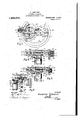
- FIG. 1 is an elevation of-the complete apparatus; the case-is shown in center section, the movement being shown in elevation except where broken away forV clearness-of illustration.
- Fig. 2 is a top view of the apparatus, reduced in size, showing the sliding cover closed
- Fig. 3' is a plan view of the movement, the upper part of the movement case including the glass dial and pointer being removed; part vof the gear wheel arm andthe movement frame are broken away; part of the caseand the reset ting plunger bushing are shown in section,
- Fig. 4 is a. side ⁇ elevation of the obverse side of the movement, in normal position, to illus trate the resetting device; the case andA dial are shown in section and broken away, the resetting lunger bushing being shown in section.
- ig. 5 is similarto Fig. 4 except 4 ⁇ that the resetting plunger is shown as pushed inward and the resetting weight raised from its seat, and
- Fig. 6 is an end view of the movement in a normal position, as seen from the resetting side, the (ase andI diaphragm being broken away.
- he complete body is preferably of cast metal and consists of the movement case
- the glass protecting cas or top 3, the latter havmg three openings, 3', for observation; three arms 3 connect' Lhe annular body, 3, with a center, 4, having a staple, 5, for suspending the apparatus b a rope or cable, not shown.
- Fig. 1 shovs thecase open and ig. 2 shows 1t closed.
- A'screw7,'-passing ing through a slot, 8, ai :'ord s a simple means to hold the'lcover open or closed.
- the weight case, 2, las a central rod,- 9,'
- e v eight as may be rethreaded ring, 12, which ,is fastened in a. ring, 14, by screw thraads as shown.
- the movementV is ⁇ held in llace by a number of studs, 17 and screws, 17', w ich studs rest on projecting brackets 18, in the case.
- the upper end of the nu vement case is rovided with a male th: lead, 19, upon w ich case, 3, screws; 20, 21 ⁇ are rubber washers,
- stud, 32 is fastened centrall to the ldiaphra 16, into which stud a link, 33, is secure by a pin or screw 34; this link is connected to a lever, 35, which' articulates in a bracket 36, the other end of said lever having an elon ated slot, 35', in which a in 35* or screw s ides, said pin being place in a crank arm, 38',
- v pierced and a helical spring, 42 is fastened in said piercings to4 prevent lost motion.
- the resetting mechanism is placed on'the .opposite-sides of the movement hereinbefore described, and consists of a sliding weight
- a bifurcated stud, 49 placed centrally in the top of the weight, has a pin 50 ⁇ passing through it, which pin engages the freeend of the L crank, 51, mentioned above, the jaws, 52, straddling said v in and permitting lateral movement; the ower arm of the crank 51 is offset to aline with the center of the weight as shown.
- a friction spring, 64 presses againstthe pinion shaft, 28, while another spring, 65, presses against the gear wheel-shaft, ⁇ 2 the riction of the two springs vpreventing free motion of the two shafts until actuated b the. movement in operation in either d1- rection.
- the pointed shape of the case permits the apparatus to enter the water with little resistance and no'splashing.
- the holes 13'the depth pressure acts against the diaphragm which is pressed upward,.carrying with it the link,
- add weight may be given to the apparatus by insertin -any number' o'f lead weights, 11, in the ower case.
- a-body having a waterti ht movementcase, a movement and a dial in said case, a link, a diaphragm pressing upwardly against said ink, said link connecting said diaphragm with said movement whereby said movement is actuated in one direction' only, and means for resetting said movement to zero, said means comprisingA a weight which ⁇ actuates the movement in one direction4 only, a lower case provided with radial openings for ythe ingress and egress of water, and an upper ca'se provided with a series of radial arms and means for closing the openings between said arms.
- a body having a watertight movement case, a movement, ⁇ means for actuating said movement in a forward direction, and n independent means 4for actuati said movement in a reverse direction, an ⁇ va dial indimounted on said movement above said dial, the entiremovement and indicating means being placed in said watertight case.
- a body consisting of two cone shaped'cases positione above and below and attached to a cylindi ⁇ cal watertight move# ment case, said watei tight movement case being closed against the entrance of water by a glass diskv betwee n two annular rubber washers above and telow said glass disk l above said movement case, -and Aclosed a nst the entrance cf water at the bottom o said case ⁇ by a meal diaphragm having annular corru ions a movement anda link, said diap ragm'l eing connected to said movement in 'said casi ⁇ by said link whereby an upward pressure a gainst said diaphragm actuates said moven ent in one direction only, and means with n said watertight ease for actuating said mo vement in a reverse direction for resetting :laid movement to zero. Signed at Sellersv ille
Landscapes
- Life Sciences & Earth Sciences (AREA)
- Hydrology & Water Resources (AREA)
- Physics & Mathematics (AREA)
- Engineering & Computer Science (AREA)
- General Physics & Mathematics (AREA)
- Radar, Positioning & Navigation (AREA)
- Remote Sensing (AREA)
- Toys (AREA)
Description
Pl SCHUBERT.
SOUNDING APPARATUS.
APPLICATION FILEDV KAR. 1'1, 1911.
2 BEEETS' 'SHEET 1.
NVENTOR Schwert BY Patented Nov. 14, 1911.
Frederick l TTRNEY I'. SCHUBERT.
SOUNDING APPARATUS.
APPLIEJATION rILnD 11.111,11, 1911.
25 127' 26 64 s 1 =1 21 J1 57 J3 J5 45 fsk' f 0 Il 5.9 ll/ 4 550.51 49 58 l 1 44.
48 a V 27 l 23\ a# ,27 6o` 25 ,2 6 Y f' 1 Y 3o' e 26 e4 g 61 24:--
, a1 4.a ze 51 6 5a 23 53 46 j a, Jg gy/ 4f 27, `,/l 25 /7/ 24 .5 5'5" 6 38 45.- Ftg. 5 46 r' 45 J7 o 47 52 .56 f 50E; .f3 36 7 49 l 30 39 j l f1 f6 4f* 4a /32 F196 WITNESSES: 16 A IP VENTOR Frederick SYchubnrT,
2,11* A` TORNEY Pana Nov. 14,1911.
y lower UNTTED STATES PATENT oEEIcE.
FBED-EBIGK SCHUBERT, 0F SELLEBBVILLE, PENNSYIN SOUNDING APPARATUS.
lpecmcation of Letters Patent..
Patenti d Nov. 14, 1911.
v.Application led latch 17, 1911. Serial llo. 815,027.
To all whom it mary` camera:
Be it known that I, Fnnpnarcx SCHUBERT, acitizen of the United States, and resident of Sellersville, in the county of Bucks and .State of Pennsylvania, have invented cer- I until purposely resietbyinverting or by pushing aretting plunger inward or that purose.
A vfurther object is to provide a case, Bginted ateach end, whereby soundings can taken while the ship is in motion without causing any excessive drag or resistance on the apparatus or on the line from which it is sus ended.` l
' further object is to provide a means for aduating the weight ofthe apparatus to a a t it for shallow or dee sea sounding.
M invention is shown in t e accompanying` rawings in whichigure 1 is an elevation of-the complete apparatus; the case-is shown in center section, the movement being shown in elevation except where broken away forV clearness-of illustration. Fig. 2 is a top view of the apparatus, reduced in size, showing the sliding cover closed Fig. 3' is a plan view of the movement, the upper part of the movement case including the glass dial and pointer being removed; part vof the gear wheel arm andthe movement frame are broken away; part of the caseand the reset ting plunger bushing are shown in section,
-tlie movement being in a normal position,
that is, at rest, as shown in Fig. 1. Fig. 4 is a. side `elevation of the obverse side of the movement, in normal position, to illus trate the resetting device; the case andA dial are shown in section and broken away, the resetting lunger bushing being shown in section. ig. 5 is similarto Fig. 4 except 4 `that the resetting plunger is shown as pushed inward and the resetting weight raised from its seat, and Fig. 6 is an end view of the movement in a normal position, as seen from the resetting side, the (ase andI diaphragm being broken away.
In Letters Patent No 987,260 granted to me March 21, 1911, for a sounding apparatus, the movement 1s actuated by a Bourdon tube spring, and is la ked when the bottom-has been touched )r reached. In the present application the movement is actuated by a corrugated metallic diaphragm against which the water resses, the movement being connected v itl; said diaphra by links and levers as will be more hereinafter described. The dial is graduated in feet or fathom: L, a. ointer indicatinthe vertical depthre ache by the sounder.
he complete body is preferably of cast metal and consists of the movement case,
41, the inverted conical. weight case,2, and
the glass protecting cas or top, 3, the latter havmg three openings, 3', for observation; three arms 3 connect' Lhe annular body, 3, with a center, 4, having a staple, 5, for suspending the apparatus b a rope or cable, not shown. A rotarys li ing cover, 6, having three openings 6', ivhich aline with the openings, 3", between the arms when the cover 1s an open posi' ion, or which completel closes the top ase when rotated is rovi ed. Fig. 1 shovs thecase open and ig. 2 shows 1t closed. A'screw7,'-passing ing through a slot, 8, ai :'ords a simple means to hold the'lcover open or closed.
phragm. This weightI case lis fastened to a,
The weight case, 2, las a central rod,- 9,'
e v eight as may be rethreaded ring, 12, which ,is fastened in a. ring, 14, by screw thraads as shown. The
movement case, 1, con: ists of said ring, 14, which is fastened to whe lower edge by' a series of screws, 15, a metallic diaphragm, 16, being tightly screwed between the said ring an case, as sh( wn in Fig. 1. The movementV is` held in llace by a number of studs, 17 and screws, 17', w ich studs rest on projecting brackets 18, in the case. The upper end of the nu vement case is rovided with a male th: lead, 19, upon w ich case, 3, screws; 20, 21` are rubber washers,
'the femaleV thread .of the glass protecting disk,22, to make the` lLnterior of the movement case watertight. A dial, 23, rests in a4, the
I the case above the movement and is held in sitioned, the said arms standing at right' angles with themovement frame when in a normal position, as shown in Fig. 3. Fastened to and below said frame, 24, is a plate, 31, havin a series of suspended brackets 36, 39 an 53 which have bearin 36'* 39, and 53* for the several levers an cranks of the movement. A forked. stud, 32, is fastened centrall to the ldiaphra 16, into which stud a link, 33, is secure by a pin or screw 34; this link is connected to a lever, 35, which' articulates in a bracket 36, the other end of said lever having an elon ated slot, 35', in which a in 35* or screw s ides, said pin being place in a crank arm, 38',
which extends at right angles from a lever,
38, fulcrumed in a bracket, 39, the lever extendin upward vabove the lower frame,
`grec end, 38", of said lever being bent at'right angles to stand in the path o the in, 30, in the arm, 29, of the gear wheel. A s ot, 40, in the lower movement frame, permits movement of the .free end, 38", of lever 38. The arm, 41, extending outward from the lever 38 op osite the crank arm 38' acts as a counter ba ance. The link;
33, and the lower end ofthe lever, 38, are
v pierced and a helical spring, 42, is fastened in said piercings to4 prevent lost motion.
. The resetting mechanism is placed on'the .opposite-sides of the movement hereinbefore described, and consists of a sliding weight,
44, suspended from and upon two rods, 45, fastened to a curved plate, 46 (which is a continuation of plate, 31) the free ends of said rods passing through'a plate, 47, one
end of which extends outward beyond the circumference of the weight, the said end being pierced and provided with' a helical spring, 48, the upper end of which is fastened in the piercing in thecrank, 51 A bifurcated stud, 49, placed centrally in the top of the weight, has a pin 50` passing through it, which pin engages the freeend of the L crank, 51, mentioned above, the jaws, 52, straddling said v in and permitting lateral movement; the ower arm of the crank 51 is offset to aline with the center of the weight as shown. The upper-arm,
51', of the crank connects with aslide,l 55,
suitably mounted between parallel bearings, 56, thenslide 4extending and -projecting beyond the movement plate, -A l 57, is i A friction spring, 64, presses againstthe pinion shaft, 28, while another spring, 65, presses against the gear wheel-shaft,\2 the riction of the two springs vpreventing free motion of the two shafts until actuated b the. movement in operation in either d1- rection. v
Such being the construction, the operation, which Vhas partly been explained, is asI follows z-When a sounding is ,to be taken, the apparatus is inverted and iven a sudden Jerk downward so that t e resetting weight, 44, will cause that part of the move- `ment which it actuates to set the indicator to zero. The slidingcover, 6, is closed and 4the apparatus is lowered into the water.
The pointed shape of the case permits the apparatus to enter the water with little resistance and no'splashing. As the water entersthrough the holes, 13,'the depth pressure acts against the diaphragm which is pressed upward,.carrying with it the link,
33, and actuating the lever, 35, and'crank,
38, the bent upper end, 38, pressing a ainst the '-pin, 30, in the gear wheel, 27 and causing the pinion, its shaft and indicator to move in a forward direction, .the two friction springs, 64, 65,- preventing accidental displacement or movement. When the apparatus is raised from the water, the shape of the u per case and cover prevent the cover also 4protecting the glass against possible breakage. The cover 1s opened by rot-ating it, when released by the screw, 7, the depth indicated by the pointer on the `dial is noted, and the movement is reset to zero, by inverting as hereinbefore described, or .the cap, 63, may be unscrewed and the head, 61, of the lunger pressed inward, (as shown in Fig. 5S) whereby the movement is reset to zero, the pin, 57, on the slide, 55,
-any drag and t us there is little reslstance,
engaging the pin, 30', in the arm, 29'-, of 120 the gear Wheel, 27', and carrying the wheel around until the pin, 30, touches the free end 38" of the lever 38 and the movement isagain set in anormal condition-that is at zero. The spring, 48', pulling down on the ar'm, 51, compels the weight, 44, to remain in the position shown in Figs. 1 and 4 eating the depth,
water aboard of vent the weight' from leaving its position durngthe handling of the ap aratus. n For deep sea sounding, add weight may be given to the apparatus by insertin -any number' o'f lead weights, 11, in the ower case.
What I claim is 1. In asounding apparatus, a-body having a waterti ht movementcase, a movement and a dial in said case, a link, a diaphragm pressing upwardly against said ink, said link connecting said diaphragm with said movement whereby said movement is actuated in one direction' only, and means for resetting said movement to zero, said means comprisingA a weight which `actuates the movement in one direction4 only, a lower case provided with radial openings for ythe ingress and egress of water, and an upper ca'se provided with a series of radial arms and means for closing the openings between said arms.
2. In a sounding apparatus of the kind described, a body having a watertight movement case, a movement, `means for actuating said movement in a forward direction, and n independent means 4for actuati said movement in a reverse direction, an `va dial indimounted on said movement above said dial, the entiremovement and indicating means being placed in said watertight case.
, 3. Ina sounding apparatus of the kind a movingship and to prep er case and a pointed lower case, a watertight movement case, siid pointed cases being fastened respectively aboveand below said cylindrical wateri ight movementcase, a movement in 'sai d watertight case, means for actuating sl-id movement in one 'direction only, and in lependent means for actuating said movemc nt in a reverse direction for reset-tin said movement to zero.
4.` In a soun ing apparatus of the kind described, a body consisting of two cone shaped'cases positione above and below and attached to a cylindi` cal watertight move# ment case, said watei tight movement case being closed against the entrance of water by a glass diskv betwee n two annular rubber washers above and telow said glass disk l above said movement case, -and Aclosed a nst the entrance cf water at the bottom o said case `by a meal diaphragm having annular corru ions a movement anda link, said diap ragm'l eing connected to said movement in 'said casi` by said link whereby an upward pressure a gainst said diaphragm actuates said moven ent in one direction only, and means with n said watertight ease for actuating said mo vement in a reverse direction for resetting :laid movement to zero. Signed at Sellersv ille in the county of Bucks and State of ,ennsylvania this 15th Q5 dayof'Mrch, E911, FREDERICK SCHUBERT.'
Witnesses: g
Bienne Wn( mit,
3 described, a body comprisinga pointed up- WM. A. Ihm] son.
Priority Applications (1)
| Application Number | Priority Date | Filing Date | Title |
|---|---|---|---|
| US61502711A US1008566A (en) | 1911-03-17 | 1911-03-17 | Sounding apparatus. |
Applications Claiming Priority (1)
| Application Number | Priority Date | Filing Date | Title |
|---|---|---|---|
| US61502711A US1008566A (en) | 1911-03-17 | 1911-03-17 | Sounding apparatus. |
Publications (1)
| Publication Number | Publication Date |
|---|---|
| US1008566A true US1008566A (en) | 1911-11-14 |
Family
ID=3076877
Family Applications (1)
| Application Number | Title | Priority Date | Filing Date |
|---|---|---|---|
| US61502711A Expired - Lifetime US1008566A (en) | 1911-03-17 | 1911-03-17 | Sounding apparatus. |
Country Status (1)
| Country | Link |
|---|---|
| US (1) | US1008566A (en) |
Cited By (3)
| Publication number | Priority date | Publication date | Assignee | Title |
|---|---|---|---|---|
| US2541256A (en) * | 1946-01-22 | 1951-02-13 | Manning Maxwell & Moore Inc | Pressure cooker gauge |
| US2700306A (en) * | 1954-06-28 | 1955-01-25 | Joe W Johnson | Shore wave recorder |
| US2743611A (en) * | 1954-12-09 | 1956-05-01 | Weston Electrical Instr Corp | Tank thermometer |
-
1911
- 1911-03-17 US US61502711A patent/US1008566A/en not_active Expired - Lifetime
Cited By (3)
| Publication number | Priority date | Publication date | Assignee | Title |
|---|---|---|---|---|
| US2541256A (en) * | 1946-01-22 | 1951-02-13 | Manning Maxwell & Moore Inc | Pressure cooker gauge |
| US2700306A (en) * | 1954-06-28 | 1955-01-25 | Joe W Johnson | Shore wave recorder |
| US2743611A (en) * | 1954-12-09 | 1956-05-01 | Weston Electrical Instr Corp | Tank thermometer |
Similar Documents
| Publication | Publication Date | Title |
|---|---|---|
| US2455200A (en) | Liquid level indicator | |
| US2265149A (en) | Photoelectric device for opening or closing a switch at any selected altitude | |
| US2653478A (en) | Gauge for liquid containers | |
| US1348015A (en) | Leak-detector for vessels | |
| US2736386A (en) | Explosion suppression device | |
| US3359792A (en) | Energy measuring apparatus | |
| US39114A (en) | Improvement in instruments for indicating the depth of water in cisterns | |
| US2331542A (en) | Thermohydrometer | |
| US2690675A (en) | Fishing indicator | |
| US2312307A (en) | Hydrometer | |
| GB507991A (en) | Improvements in rate of change of pressure indicators such as rate of climb indicators for aircraft | |
| US2148567A (en) | Device for the classification of handwriting | |
| US3302167A (en) | Airspeed warning device | |
| US1664417A (en) | Combined statoscope and rate-of-climb indicator | |
| US2425762A (en) | Azimuth indicator | |
| US77809A (en) | Thomas flin | |
| US1308620A (en) | Charles e | |
| US2320505A (en) | Flight position and force indicating | |
| US1308557A (en) | Climb-indicator fob aibcrafts | |
| GB452596A (en) | Improvements in or relating to control valves | |
| DE864159C (en) | Differential manometer | |
| US2069279A (en) | Liquid measuring apparatus | |
| US1945042A (en) | Liquid level gauge | |
| US27282A (en) | Fiee-alarm | |
| US578725A (en) | Water-indicator and alarm |