US1008561A - Dynamo-electric machine. - Google Patents
Dynamo-electric machine. Download PDFInfo
- Publication number
- US1008561A US1008561A US49697809A US1909496978A US1008561A US 1008561 A US1008561 A US 1008561A US 49697809 A US49697809 A US 49697809A US 1909496978 A US1909496978 A US 1909496978A US 1008561 A US1008561 A US 1008561A
- Authority
- US
- United States
- Prior art keywords
- pole
- members
- coils
- electric machine
- dynamo
- Prior art date
- Legal status (The legal status is an assumption and is not a legal conclusion. Google has not performed a legal analysis and makes no representation as to the accuracy of the status listed.)
- Expired - Lifetime
Links
- 238000004804 winding Methods 0.000 description 9
- 241000239290 Araneae Species 0.000 description 3
- 230000004907 flux Effects 0.000 description 3
- 238000010276 construction Methods 0.000 description 2
- 150000002500 ions Chemical class 0.000 description 2
- 238000003475 lamination Methods 0.000 description 2
- 239000004020 conductor Substances 0.000 description 1
- 238000006073 displacement reaction Methods 0.000 description 1
- 239000000696 magnetic material Substances 0.000 description 1
- 239000002184 metal Substances 0.000 description 1
- 230000004048 modification Effects 0.000 description 1
- 238000012986 modification Methods 0.000 description 1
Images

Classifications
-
- H—ELECTRICITY
- H02—GENERATION; CONVERSION OR DISTRIBUTION OF ELECTRIC POWER
- H02K—DYNAMO-ELECTRIC MACHINES
- H02K3/00—Details of windings
- H02K3/46—Fastening of windings on the stator or rotor structure
- H02K3/50—Fastening of winding heads, equalising connectors, or connections thereto
- H02K3/51—Fastening of winding heads, equalising connectors, or connections thereto applicable to rotors only
Definitions
- My invention relates to dynamo electric machines, and more particularly to field magnet structures Iin which the winding is distributed, as distinguished from those structures which have definite or salient poles.
- Such field magnet structures are known in the art as the smooth core type. In such structures the central portion of the pole is magnetized by all the turns on the pole, while outside of the center portion it is magnetized only by the turns surrounding the outside portion.
- In building these field magnets it is usual to distribute the winding only in a small number of coils. They have been built heretofore with a uniform airgap, and when the winding is distributed in a small number of coils, the magnetic density on one side of a coil will be considerably less than on the other side of the same coil.
- the core between the coils of the winding is preferably made up of members or coil holders placed in position as shown and described in the patent to Sulzberger, No. 902,020, patented October 27, 1908.
- 1 represents the spider carrying the revolving field magnet of a dynamo electri; machine.
- the core 2 o f the field magnet is mounted on the spider 1 and in the particular machine illustrated is provided with ten polar portions.
- the windings of the field magnet comprise similar sets of conductors, each 1n the form of two loops or coils 3 and 4, one set surrounding each polar portion.
- the coils 3 and 4 are ield in place by sets of coil holders or meml ers 8, 9 and 10, made of magnetic material :,nd preferably laminated.
- Each polar or :ion of the field magnet structure is ma e 1' p of two members 9, two members 10, and :t central member l1.
- Both of the coils 3 and et surround the members 10 and 11, which t gether form the central part of the pole.
- the members 9 are surrounded only by th e outside coil 4, and the members 8 are no 'f surrounded by any of the coils.
- the central part of the pole is magnetized by twice the number of ampere turns that the members 9 are magnetized by, that is., of course, with the ampere-turns of the c( ils 3 and 4 the same.
- the reluctance of the path of the fiux depends mainly upon the air-gap, and is practically proportional t( it, and in order to get a sinusoidal distril ution of iux, I have provided a variable tir-gap between the armature and the field magnet, as is clearly seen in Fig. 3, in whicl ⁇ 12 represents a lamination of the armatur s.
- This variable airgap is produced by -zonstructing the coil holders constitutingV 1he pole portions so that they diverge frorr the periphery of the armaturein a direction away from the center of the pole in the n anner hereinafter described.
- the members 9 diverge from ;he periphery of the armature toward the :ides of the pole at a greater angle than tl: ⁇ at of the holders or members forming tht center part of the pole.
- the portions of the members 9 which are toward the center )f the pole are longer than the adjacent por :ions of the members sol 10.
- the air-gap at the end 15 of the member 9 is the same as that at the center 13 olf the pole.
- the coils 3 and 4 have end turns or connections 17. These end turns must' be supported so that they will be held rigidly and rmly in place against the enormous centrifugal forces exerted thereon when the re- 'volving field magnet is ro-tating at high speed.
- the end flange 18, which is keyed on the spider 1 and holds the laminations in place, has arms 19 extending therefrom.
- the annular end cover 20 is fastened to the arms 19 in usual manner, and in accordance with my invention has its outsideperiphery tapered.
- the cylindrical cover 2l has a portion 22 of its inside periphery tapered in the same direct-ion as the end cover, the tapered portion of the end cover and cylindrlcal cover cooperating, as shown in F 1g. 2.
- Flat pieces of metal 28 are bolted to the end cover and abut against and exert a lateral pressure upon the end of the cylindrical cover in order to stretch the cylindrical cover, and to compress the end cover, so that the surfaces of the cylindrical cover and the end cover will remain in contact and the cylindrical cover will remain centered when the field magnet is revolving at high speed.
- the end turns 17 are clamped in place against radial displacement by means of the members 24 which are bolted to the cylindrical cover by means of bolts 25, and thus the end turns are clamped between the members 24 and the cylindrical cover 21.
- a eld ma et structure having a core, a' distributed vvlnding comprising a plurality of coils for' each po e, and members forming the poles arranged to space apart and secure in position said coils, the members forming the center part of each pole diverging from the periphery of the armature from the center of the pole toward each side, and the other mem; bers forming a part of the pole diverging from the periphery of the armature toward the sides of the pole, the port-ions of said other members toward the center of the pole being longer than the adjacent portions of the members forming the center part of the po e. 2.
- a field magnet structure having a core, a distributed winding comprising a plurality of coils for each pole, and members arranged to space apart vand secure in position said coils, the mem- 'bers forming the center part of each pole diverging from the periphery of the armature from the center of the pole toward each jside, and the other members forming a part of the pole diverging from the periphery of -the armature toward the sides of the pole at a greater angle than that of the members forming the center of the pole, the portions of said other members toward the center of the pole being longer than the adjacent portions of the members forming the center part of the pole.
- a rotatable member comprising a core, a winding thereon having end turns or connections, an end cover and cylindrical cover for said end turns, said end cover and cylindrical cover having cooperating tapered portions which keep the cylindrical cover properly centered when the latter is subjected to centrifugal forcel 4.
- a rotatable member comprising a core, windings thereon havin end turns or connections, an end cover ang a cylindrical cover for said end turns, said end cover having its outside periphery tapered and said cylindrical cover having a portion of its inside periphery tapered to cooperate with the taper on said end cover.
- a rotatable member comprising a core, windings thereon havin end turns or connections, an end cover an a cylindrical cover for said end turns, said end cover having its outsideperiphery tapered and said cylindrical cover having a portion of its inside periphery tapered to cooperate with the taper on said en d cover, and a member fastened to said end cover exerting a lateral pressure on said cylindrical cover.
Landscapes
- Engineering & Computer Science (AREA)
- Power Engineering (AREA)
- Iron Core Of Rotating Electric Machines (AREA)
Description
i V I b5 rHelm-5Greii-St, L
H. G. REIST. DYNAMO ELECTRIC MACHINE. APPLICATION FILED In 1s, 1909.
Patent ad Nov. 14, 1911.
lBHEETB-SHEET 2.
`Witrn eases: Inven Lor:
' r oqttfg.
CoLUMBM PLANuaRM-n co..w^sH|Hn-ror4. ILC.
UNTTED sTATEs PATENT oEEroE.,
HENRY G'. REIST, OF SCHENECTADY, NEW YORK, ASSIGNOR TO ('rENERAL ELECTRIC COMPANY, A CORPORATION OF NEW YORK.
DYNAMO-ELECTRIC MACHINE.
To all whom it may concern.'
Be it known that I, HENRY G. REIST, a citizen of the United States, residing at Schenectady, county of Schenectady, State of New York, have invented certain new and useful Improvements in Dynamo-Electric Machines, of which the following is a specification.
My invention relates to dynamo electric machines, and more particularly to field magnet structures Iin which the winding is distributed, as distinguished from those structures which have definite or salient poles. Such field magnet structures are known in the art as the smooth core type. In such structures the central portion of the pole is magnetized by all the turns on the pole, while outside of the center portion it is magnetized only by the turns surrounding the outside portion. In building these field magnets it is usual to distribute the winding only in a small number of coils. They have been built heretofore with a uniform airgap, and when the winding is distributed in a small number of coils, the magnetic density on one side of a coil will be considerably less than on the other side of the same coil. In order to improve the flux distribution, I shape the faces of the portions of the core between the coils which make up the pole, so that they diverge from the periphery of the armature of the dynamo electric machine in a direction away from the centerof the pole, the divergence of the several faces being such as to produce a substantially sinusoidal distribution of flux. The core between the coils of the winding is preferably made up of members or coil holders placed in position as shown and described in the patent to Sulzberger, No. 902,020, patented October 27, 1908.
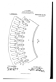
Other features of novelty which characterize my invention are pointed out in the claims annexed to and forming a part of this specification. For a better understanding of my invention, however, reference may be had to the followingdescription taken in connection with the accompanying drawing, in which- Figure 1 is an end elevation of a revolv` ing field magnet structure of a dynamo electric machine embodying my invention, with parts broken away and in section; Fig. 2 is a sectional view of the construction shown in Fig. 1; and Fig. 3 is an enlarged Specication of Letters Patent.
Application filed May 19, 1909.
Patent ed Nov. 14, 1911.
serial No. 496,973.
view of a portion of tl le same field magnet structure with the cols removed for the sake of clearness.
Referring to the dr twings, 1 represents the spider carrying the revolving field magnet of a dynamo electri; machine. The core 2 o f the field magnet is mounted on the spider 1 and in the particular machine illustrated is provided with ten polar portions. The windings of the field magnet comprise similar sets of conductors, each 1n the form of two loops or coils 3 and 4, one set surrounding each polar portion. The coils 3 and 4 are ield in place by sets of coil holders or meml ers 8, 9 and 10, made of magnetic material :,nd preferably laminated. Each polar or :ion of the field magnet structure is ma e 1' p of two members 9, two members 10, and :t central member l1. Both of the coils 3 and et surround the members 10 and 11, which t gether form the central part of the pole. The members 9 are surrounded only by th e outside coil 4, and the members 8 are no 'f surrounded by any of the coils. Therefor f, the central part of the pole is magnetized by twice the number of ampere turns that the members 9 are magnetized by, that is., of course, with the ampere-turns of the c( ils 3 and 4 the same. The reluctance of the path of the fiux depends mainly upon the air-gap, and is practically proportional t( it, and in order to get a sinusoidal distril ution of iux, I have provided a variable tir-gap between the armature and the field magnet, as is clearly seen in Fig. 3, in whicl` 12 represents a lamination of the armatur s. This variable airgap is produced by -zonstructing the coil holders constitutingV 1he pole portions so that they diverge frorr the periphery of the armaturein a direction away from the center of the pole in the n anner hereinafter described. The member.: 10 and 11, forming the center partof the role, diverge from the periphery of the arm: ture from the center 13 of the poles toward each side 14, so that the air-gap at each sido, is substantially double that at the center o t thepole. The members 9 diverge from ;he periphery of the armature toward the :ides of the pole at a greater angle than tl:` at of the holders or members forming tht center part of the pole. The portions of the members 9 which are toward the center )f the pole are longer than the adjacent por :ions of the members sol 10. The air-gap at the end 15 of the member 9 is the same as that at the center 13 olf the pole. The construction of the members, as described above, gives a smooth curve of flux distribution, which is substantially sinusoidal.
The coils 3 and 4 have end turns or connections 17. These end turns must' be supported so that they will be held rigidly and rmly in place against the enormous centrifugal forces exerted thereon when the re- 'volving field magnet is ro-tating at high speed. The end flange 18, which is keyed on the spider 1 and holds the laminations in place, has arms 19 extending therefrom. The annular end cover 20 is fastened to the arms 19 in usual manner, and in accordance with my invention has its outsideperiphery tapered. The cylindrical cover 2l has a portion 22 of its inside periphery tapered in the same direct-ion as the end cover, the tapered portion of the end cover and cylindrlcal cover cooperating, as shown in F 1g. 2. Flat pieces of metal 28 are bolted to the end cover and abut against and exert a lateral pressure upon the end of the cylindrical cover in order to stretch the cylindrical cover, and to compress the end cover, so that the surfaces of the cylindrical cover and the end cover will remain in contact and the cylindrical cover will remain centered when the field magnet is revolving at high speed. The end turns 17 are clamped in place against radial displacement by means of the members 24 which are bolted to the cylindrical cover by means of bolts 25, and thus the end turns are clamped between the members 24 and the cylindrical cover 21.
I have illustrated my invention in connection with a ten-pole eld magnet having two coils per pole, but it is evident' that it is not limited to any number of poles or any number of coils p'er pole. With a greater number of coils per pole the amount that each coil holder diverges from the periphery of the armature must' be modified accordingly.
I aim in the appended claims to cover all modifications which do not depart from the spirit and scope of my invention.
What I claim as new and desire to secure by Letters Patent of the United States is,
1. In combination with the armature of a dynamo electric machine, a eld ma et structure having a core, a' distributed vvlnding comprising a plurality of coils for' each po e, and members forming the poles arranged to space apart and secure in position said coils, the members forming the center part of each pole diverging from the periphery of the armature from the center of the pole toward each side, and the other mem; bers forming a part of the pole diverging from the periphery of the armature toward the sides of the pole, the port-ions of said other members toward the center of the pole being longer than the adjacent portions of the members forming the center part of the po e. 2. In combination with the armature of a dynamo electric machine, a field magnet structure having a core, a distributed winding comprising a plurality of coils for each pole, and members arranged to space apart vand secure in position said coils, the mem- 'bers forming the center part of each pole diverging from the periphery of the armature from the center of the pole toward each jside, and the other members forming a part of the pole diverging from the periphery of -the armature toward the sides of the pole at a greater angle than that of the members forming the center of the pole, the portions of said other members toward the center of the pole being longer than the adjacent portions of the members forming the center part of the pole.
3. In a dynamo electric machine, a rotatable member comprising a core, a winding thereon having end turns or connections, an end cover and cylindrical cover for said end turns, said end cover and cylindrical cover having cooperating tapered portions which keep the cylindrical cover properly centered when the latter is subjected to centrifugal forcel 4. In a dynamo electric machine, a rotatable member comprising a core, windings thereon havin end turns or connections, an end cover ang a cylindrical cover for said end turns, said end cover having its outside periphery tapered and said cylindrical cover having a portion of its inside periphery tapered to cooperate with the taper on said end cover.
5. In a dynamo electric machine, a rotatable member comprising a core, windings thereon havin end turns or connections, an end cover an a cylindrical cover for said end turns, said end cover having its outsideperiphery tapered and said cylindrical cover having a portion of its inside periphery tapered to cooperate with the taper on said en d cover, and a member fastened to said end cover exerting a lateral pressure on said cylindrical cover.
In witness whereof, I have hereunto set my hand this 18th day of May 1909.
HENRY G. HEIST. Witnesses:
BENJAMIN B. HULL, HELEN ORroRD.
copies ot this patent may be obtained for ve cents each, byv addressing the "Commissionerof Patents,
Washington, D. 0.
Priority Applications (1)
| Application Number | Priority Date | Filing Date | Title |
|---|---|---|---|
| US49697809A US1008561A (en) | 1909-05-19 | 1909-05-19 | Dynamo-electric machine. |
Applications Claiming Priority (1)
| Application Number | Priority Date | Filing Date | Title |
|---|---|---|---|
| US49697809A US1008561A (en) | 1909-05-19 | 1909-05-19 | Dynamo-electric machine. |
Publications (1)
| Publication Number | Publication Date |
|---|---|
| US1008561A true US1008561A (en) | 1911-11-14 |
Family
ID=3076872
Family Applications (1)
| Application Number | Title | Priority Date | Filing Date |
|---|---|---|---|
| US49697809A Expired - Lifetime US1008561A (en) | 1909-05-19 | 1909-05-19 | Dynamo-electric machine. |
Country Status (1)
| Country | Link |
|---|---|
| US (1) | US1008561A (en) |
Cited By (1)
| Publication number | Priority date | Publication date | Assignee | Title |
|---|---|---|---|---|
| US3081412A (en) * | 1958-10-23 | 1963-03-12 | Laborde & Kupfer | Alternator armature teeth |
-
1909
- 1909-05-19 US US49697809A patent/US1008561A/en not_active Expired - Lifetime
Cited By (1)
| Publication number | Priority date | Publication date | Assignee | Title |
|---|---|---|---|---|
| US3081412A (en) * | 1958-10-23 | 1963-03-12 | Laborde & Kupfer | Alternator armature teeth |
Similar Documents
| Publication | Publication Date | Title |
|---|---|---|
| US579012A (en) | scheeffer | |
| US1465251A (en) | Electric machine | |
| US2863077A (en) | Dynamoelectric field structure | |
| US450219A (en) | collins | |
| US427294A (en) | Dynamo-electric machine | |
| US465808A (en) | thttry | |
| US791492A (en) | Dynamo-electric machine. | |
| US323975A (en) | Dynamo-electric or electro-dynamic machine | |
| US349615A (en) | Signor to george westing house | |
| US1193897A (en) | holbech | |
| US923614A (en) | Armature construction. | |
| US899447A (en) | Dynamo-electric machine. | |
| US555544A (en) | Dynamo-electric machine and electric motor | |
| US342588A (en) | New toek | |
| US270781A (en) | Armature for dynamo-electric machines | |
| US2566238A (en) | Dynamoelectric machine | |
| US895887A (en) | Acyclic machine. | |
| US339772A (en) | heeina | |
| US472943A (en) | Dynamo-electric machine | |
| US450975A (en) | Dynamo-electric machine or motor | |
| US262544A (en) | jenney | |
| US232910A (en) | houston | |
| US451242A (en) | Armature for electric motors and generators | |
| US800382A (en) | Dynamo-electric machine. | |
| US288818A (en) | Dynamo-electric machine |